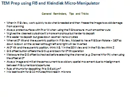
Kleindiek MicroManipulator General Reminders Tips and Tricks When in FIB view work quickly to do what is needed and then freeze the image to avoid damage from scanning Always protect surface with ID: 383203
Download Presentation The PPT/PDF document "TEM Prep using FIB and" is the property of its rightful owner. Permission is granted to download and print the materials on this web site for personal, non-commercial use only, and to display it on your personal computer provided you do not modify the materials and that you retain all copyright notices contained in the materials. By downloading content from our website, you accept the terms of this agreement.
Slide1
TEM Prep using FIB and Kleindiek Micro-Manipulator
General Reminders, Tips and Tricks
When in FIB view, work quickly to do what is needed and then freeze the image to avoid damage from scanning
Always protect surface with
Pt
or W when using the FIB to ensure much smoother cuts
W gives the cleanest cuts since it’s more amorphous but harder to deposit
Pt
is easier to deposit but goes down as small
nano
-crystals
When at 0
o
tilt and the
eucentric
position in FIB view, it is best to have FIB Scan Rotate = 180
o
so down is down on the screen although left and right will be inverted
At 0
o
tilt and the
eucentric
position, think X & Y in the SEM view and in the FIB view think Z
GIS offset button offsets the GIS up and back for 0
o
tilt operation
Make sure the GIS offset is checked before selecting the channel (
e.g.
Channel 4 for
Pt
) when using the offset at 0
o
Always image and mill at the same current to avoid any spatial movement due to misalignment between FIB currents and apertures
Rule of thumb for depositing
Pt
is 5-6
pA
/
m
m
2
It is best to aim for 8-10 minutes/thickness in micronsSlide2
TEM Prep using FIB and Kleindiek Micro-Manipulator
Overview
e-beam deposition of
Pt
FIB deposition of
Pt
FIB milling of trapeziums
FIB “U-Cut” to create free-standing structure (except for remaining tab)
Pt
welding to micro-manipulator
FIB milling to etch remaining tab
Attaching section to TEM Grid
FIB milling to thin section to TEM thickness
Final low kV FIB milling to reduce milling damage to sectionSlide3
e-Beam Deposition of Pt
Start at 1 kV, 120 mm aperture, and high current mode
Find area of interest and set up
eucentric
and coincidence conditions
Make sure that SCM is off so that the touch alarm activates
At 0
o
tilt, make sure the GIS offset is checked and insert
Pt
Use the reduced area function and open the
Pt
valve to deposit a
Pt
strip over the feature of interest for a few minutesSlide4
FIB Deposition of Pt
Remove the GIS and tilt to 54oInsert the GIS (offset unchecked)
Select 100
pA
as the imaging current (Too high of current will cause milling rather than deposition)
In FIB view, find the area of interest and freeze the image
D
eposit
Pt
strip using conditions shown belowRule of thumb is to deposit Pt around 5-6pA/mm2 (size dependent; e.g. larger area may be half this value) and aim for 8-10 minutes/thickness in mmSlide5
FIB Milling of Trapeziums
Mill trapeziums on each side of the Pt strip at 54o using the conditions shown below
Use of XeF
2
flashing for improved etching is optional (insert XeF
2
channel and manually flash)
Conditions below are for
InAs
Harder materials (e.g. Si) may need higher milling currents (~5-10 nA)The trapezoid should extend past the Pt strip by at least 2-3 mm
At least 2-3
m
m overhang past
Pt
stripSlide6
FIB Milling of Trapeziums
InAs
Redeposition
Artifact
For the training session, we used
InAs
which is hard to mill properly
Lower FIB currents and XeF2 flashing were used to help with better milling
Below shows an example of
redeposition after our first attemptSlide7
Fine Polishing
FIB Milling of Trapeziums
Clean up the face of the trapezoi
d by etching a fine rectangle at 54.5
o
using the conditions shown belowSlide8
Fine Polishing
FIB Milling of Trapeziums
Clean up the other face of the trapezoi
d by etching a fine rectangle at 53.5
o
using the conditions shown belowSlide9
FIB Milling of the U-Cut
Go to 7o tilt and scan rotate the FIB image 180oImportant to use deposition mode (even though we are etching) so we can watch the structure break free in SEM image while the FIB milling is
occuring
Set time for 4 minutes but stop when it etches through
First CutSlide10
FIB Milling of the U-Cut
Second Cut
Remain at 7
o
tilt and scan rotate the FIB image 180
o
Important to use deposition mode (even though we are etching) so we can watch the structure break free in SEM image while the FIB milling is
occuring
Set time for 4 minutes but stop when it etches throughSlide11
FIB Milling of the U-Cut
Final Cut
Remain at 7
o
tilt and scan rotate the FIB image 180
o
Important to use deposition mode (even though we are etching) so we can watch the structure break free in SEM image while the FIB milling is
occuring
Set time for 4 minutes but stop when it etches through
Free standing structure remains except for small tab attached to the bulk of the sampleSlide12
Pt Welding to the Micro-Manipulator
Tilt to 0oUsing the camera view, bring in the
Kleindiek
probe into the vicinity of the sample stage making sure it will clear the sample height
Continue to move the probe so that it is visible in the low magnification SEM view
Make sure that the GIS offset is checked and bring in the GIS
Pt
source
Turn on the SCM so the touch alarm does not go off when bringing in the micro-manipulator probe
Lower the micro-manipulator probe such that it is about 1 mm above the sampleMove the probe to the region behind the behind the slice and centered in the trenchContinue to move down until the probe is about 500 mm above the slice, keeping it centeredOpen the
Pt valveOpening the valve causes the probe to vibrate so this must be down before the probe contacts the sampleSlide13
Pt Welding to the Micro-Manipulator
Switch to the FIB view using 20 pA to image (lower is better, but the contrast is low)
Move the sample down until it is visible in the FIB view
Align in the SEM view over the corner
Move down into contact using the FIB view (Z) and SEM (X & Y) view
Switch the FIB imaging current to 10
pA
and freeze the image
Deposit
Pt on the section and probe using the conditions shown belowNote this image has the support bar on the opposite side of where it normally is with respect to the probePt deposition should be done at 10 pA current for 6-8 minute
Checking for attachment can be done by touching the SEM table and looking at the vibration coupling in the imageSlide14
FIB Milling to Etch Remaining Tab
Use 100-200 pA FIB view imaging and a reduced area FIB image to etch away the remaining tab to the substrate to etch the section freeIt will be apparent when the section has been etched free (not shown)
Move M ↑ (stage goes down, M goes to higher values) to release the section now attached to the micro-manipulator probeSlide15
Attaching Section to TEM Grid
Remove the GIS
Go to Using camera view, remove the micro-manipulator and section to a safe location outside of the SEM stage
Move the stage to the TEM grid position and re-establish the
eucentric
and coincidence positions
At 0
o
tilt, turn SCM off and bring in the GIS
PtOpen the Pt vavle
and turn the SCM on so the stage alarm won’t go off while attaching the section to the TEM gridUsing the micromanipulator controls and the camera, SEM and FIB views, move the section into position above the TEM gridSlide16
Attaching Section to TEM Grid
Deposit
Pt
onto the grid and section and shown below
Although the recipe below is four 4 minutes, we did two steps of 6 minute depositions using 10
pA
First
Pt
Weld
1st
Pt
weldSlide17
Attaching Section to TEM Grid
Deposit
Pt
onto the grid and section and shown below
Although the recipe below is four 4 minutes, we did two steps of 6 minute depositions using 10
pA
Second
Pt
Weld
2nd
Pt
weldSlide18
Attaching Section to TEM Grid
Recipe not copied but etch using Deposition Mode, 30 kV:100
pA
, No Gas ID, Frequency X 20000, Frequency Y 1
Etch 6 minutes but stop when done
Remove micro-manipulator to safe or parked location away from stage using camera, SEM, and FIB views
Removing/Etching Away Micro-Manipulator
Etching Away Micro-ManipulatorSlide19
With the section now attached to the TEM grid, go to 54.5o stage tilt and use the FIB to thin the section using the conditions shown below
When thinning, you want to see some curtain at the bottom of the slice. This adds some additional support (This is controlled by the milling depth)
Near
end of thinning SEM beam reduced to 1 kV because sample becomes transparent at 5 kV.
The final window should be about 5 to 8 microns – sample width about 15 to 20
microns
XeF
2
flashed just
prior to final thinning on both sides of sample to clean up the In balls Sample needs to be thin, but greater than 120 nm as the thickness of the XeF2 reaction is about 60 nm thick (from previous measurements)
FIB Milling to Thin Section to TEM ThicknessFirst SideSlide20
FIB Milling to Thin Section to TEM Thickness
Tilt to 0o, perform a 180o compucentric
rotation and then tilt back up to 54.5
o
and FIB the other side using the conditions shown below
When
thinning, you want to see some curtain at the bottom of the
slice as this adds
some additional
support (This is controlled by the milling depth)Near end of thinning SEM beam reduced to 1 kV because sample becomes transparent at 5 kV.The final window should be about 5 to 8 microns – sample width about 15 to 20 micronsLook for the Pt receding to the top of the sample in
SEM view while milling as this is the indicator to stop (final endpoint)Watch for uneven recession – our sample bowed and the two ends receded before the middle
Second SideSlide21
Final Low kV FIB Milling to Reduce Milling Damage to Section
Tilt sample to 45o and use low kV (5 kV: 100 pA) final polishing in deposition mode for 10-60 seconds on each side
Time needed is sample dependent (TEM imaging is ultimate test)
Final polishing is being done on the opposite side from the SEM view so cannot monitor progress but can see punch through