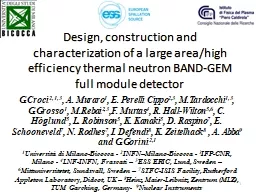
1 GCroci 213 A Muraro 1 E Perelli Cippo 23 MTardocchi 13 GGrosso 1 MRebai 23 F Murtas 4 R HallWilton 56 C Höglund 5 L Robinson 5 K Kanaki ID: 800558
Download The PPT/PDF document "Design, construction and characterizatio..." is the property of its rightful owner. Permission is granted to download and print the materials on this web site for personal, non-commercial use only, and to display it on your personal computer provided you do not modify the materials and that you retain all copyright notices contained in the materials. By downloading content from our website, you accept the terms of this agreement.
Slide1
Design, construction and characterization of a large area/high efficiency thermal neutron BAND-GEM full module detector
1
G.Croci
2,1,3
,
A. Muraro
1
,
E
. Perelli Cippo
2,3
, M.Tardocchi
1,3
, G.Grosso
1
,
M.Rebai
2,3
,F. Murtas
4
, R. Hall-Wilton
5,6
, C. Höglund
5
, L. Robinson
5
, K. Kanaki
5
, D. Raspino
7
, E. Schooneveld
7
, N. Rodhes
7
, I. Defendi
8
, K. Zeitelhack
8
, A. Abba
9
and
G.Gorini
2,1
1
Università
di Milano-Bicocca -
2
INFN–Milano-Bicocca -
3
IFP-CNR
, Milano
-
4
LNF-INFN
,
Frascati
–
5
ESS ERIC, Lund, Sweden –
6
Mittuniversitetet,
Sundsvall
,
Sweden
–
7
STFC-ISIS
Facility, Rutherford Appleton Laboratory, Didcot,
UK –
8
Heinz
Maier-Leibnitz Zentrum (MLZ),
TUM
Garching,
Germany-
9
Nuclear Instruments
Slide2Outline
Boron Array Neutron Detector (BAND)-GEM principleDesign, construction and performance of small area BAND-GEM detectors
Full module as a detector option for LOKI@ESSConclusions2
Slide3Motivation
3
European Spallation Source (ESS) will
provide higher peak neutron fluxes than existing facilities today.
Need of detector with high counting rate capabilities
in the new spallation source
Slide4The BAND-GEM detector system: an option for LoKI
4
n
beam
Sample position
5 m
3
m
Middle
bank
.
Composed
of 8 BAND-GEM full
module
Front detector
bank
.
Composed
of BAND-GEM
sectors
LoKI is a Small Angle Neutron Scattering experiment under construction at ESS.
A high neutron flux (up to 4∙10
5
n/cm
2
s) is expected
.
BAND-GEM is one of the possible option for the instrumentation of this beamline.
Tubes (SWPC) based solution are not suitable
Requirements
for LOKI detectors
Rate Capability
> 200 kHz / cm2
Time Resolution< 1 msX-Y space resolution4 mmEfficiency 50 % at 6 Å.
Requirements
for LOKI detectors
Rate Capability
> 200 kHz/cm
2
Time Res
< 1 ms
Spatial
Res
About 6 mm
Efficiency
>
35
% @
4 Å
Slide5BAND-GEM detection
principle
5
Alluminium grids coated on both sides with 10
B4
C
Using low
θ
values (few degs) the path of the neutron inside the B
4
C is increased
Higher efficiency when detector is inclined
5
cm
96
m
m
4
m
m
Triple GEM
Padded Anode
Cathode
3D
Grid
System
n
α
e-
α
10
B
4
C
10
B
4
C
10
B
4
C
10
B
4
C
n
Al=200µm
Al
θ
E
Grid
E
G
G
8
m
m
Typical tilt angle
Ѳ
=5°
V
Cathode
V
TopGrid
Slide6BAND-GEM demonstrator: design and construction
6
Triple GEM detector with padded anode
Grids stack (Active area 5x10 cm
2
)
Detector box
The calculations made for the optimization of the BAND-GEM geometry led to the development and the construction of the BAND-GEM demonstrator
Before the deposition process:
After the deposition process:
Re-tensioning with the screws
400°C
It
is
essential
to obtain
VERY STRAIGHT
strips in order to have a good electron extraction efficiency.
Padded anode (3x4 mm
2
)
Slide7Nominal 1 µm of
10
B
4
C DEPOSITION @ ESS Workshop (Linkoeping)
B4C coating performed @ Linkoeping University
Slide8Efficiency (
at
1 and 2 A) vs tilt angle
8
Test made @ EMMA (ISIS
)
Slide9Space resolution (
FWHM) vs
tilt angle
Slide10Linearity
scan
of BAND-GEM
demonstrator
relative to
Fission
Chamber
,
performed
at
reactor
power
10.1 MW.
The BAND-GEM
is
linear (relative to the
reference
FC detector) up to
about 5 MHz/cm2.
Black dots: BANDGEM count rates per cm
2
; red line: fit of the data with saturation law; purple line: linear component of the saturation law.
V
cathode
-V
TopGrid
= -10
kV
Σ
V
GEM = 870 VTilt angle = 5°
Full beam
1.8 mm attenuator
3.6 mm attenuator
High rate test
at
the ORPHEE
Reactor
@ LLB-CEA
Slide11Improved BAND-GEM
detection
principle
11
Aluminum
grids coated on both sides with
10
B
4
C
Using low
θ
values (few degs) the path of the neutron inside the B
4
C is increased
Higher efficiency when detector is inclined
96 mm
4 mm
Triple GEM
Padded Anode
Cathode
3D
Grid
System+ middle GEM
n
α
e-
α
10
B
4
C
10
B
4
C
10
B
4
C
10
B
4
C
n
Al=200µm
Al
θ
E
Grid
E
GG
8 mm
Typical tilt angle Ѳ=5°
3mm
1
mm
V
Cathode
V
TopGrid
Slide12Improved
BANDGEM demonstrator
Observed Improvement on the extraction efficiency
z
y
Extraction efficiency from the 3D grid system was improved by the insertion of the middle GEM
Study performed by shooting the neutron beam from the side through a diagnostic window
Slide14Efficiency vs neutron wavelegnth
λ
14
Test made @ CRISP (ISIS)
Slide15BAND-GEM full-module: CAD overview
15
Detector BOX
Front of the detector
GEMINI Chips Used (see A. Abba talk)
Slide16Full Module Detector: ReadOut
Anode
16
Total
n°of
channel
:
1472
Slide17BAND-GEM full-module: design and construction
17
The 3D-C assembled
The GEM foil
The padded anode
Slide18Test of the full-module @ TREFF
Neutron beam
BAND-GEM
Monochromatic neutrons with wavelenght
λ
=4.78 Å
BAND-GEM with GEMINI electronics
Slide19Working Point determination
V
cathode
Scan
V
TopGrid Scan
V
TripleGEM
Scan
V
MiddleGEM
Scan
Slide20Uniformity of the detection efficiency
Working Point
Vcathode = -14 kV
V
MiddleGEMBottom
= -8.75 kVV
MiddleGEM Top
= -8.48 kV
V
TopGrid
= - 5 kV
V
GEM1Top
= -2.7 kV
E
T1
=E
T2
= 5 KV/cm
E
ind
= 5 kV/cm
ΣΔ
GEM = 900 V
PRELIMINARY
Tilting angle Ѳ between 1° and 2°
Slide21Efficiency vs
neutron
wavelength @EMMA
Tilting angle
Ѳ
=
8
°
Slide22Spatial resolution
vs neutron
wavelength
Slide23Test of the full-module @ LARMOR beam line (SANS instrument). Preliminary results.SANS measurement performd with a
concentrated ludox silica dispersion sample. With this sample, the expected 2d map on the detector position is a circular ring
moving to larger radius at longer wavelengths.
Neutron beam
Sample
BAND-GEM
1,5 m
BAND-GEM full module with Cd mask
Slide24Test of the full-module @ LARMOR beam line (SANS instrument). Preliminary results.
C
ircular ring
Slide25Conclusions
The test made with neutrons have shown that the BAND-GEM technology allows a neutron detection efficiency > 40% for
λ≥2 Å and is able to sustain the high rate expected at ESSThe BAND-GEM full module was designed during 2017 and realized at the beginning of 2018
The tests with neutrons performed with the BAND-GEM full module have shown that the detector has performace similar to what was obtained with the small BANDGEM demonstratorsThe BAND-GEM full module was also tested in a real SANS experiment and t
he data analysis is still ongoing.
Even if all the requirements for LOKI were satisfied,
the experiment board DID NOT select the BANDGEM detector
option for
LOKI.
A
straw
tubes based solution
was preferred.
Slide26Thank you26
Slide27EGEM<100 kV/cmE
D,ET1E
T2 3 kV/cmEi 5kV/cm
Triple GEM
for thermal neutrons
Ar/CO
2
70/30%
Q=2.31
MeV
E
Li
=0.84
MeV
E
α
=1.47
MeV
σ
abs
=3840 b (E
n
=25
meV
)
Back to back
emission
α
range(B4C)≈3.4 µmLi
range(B4C)≈1.7 µmPerformance obtained with the bGEMInsensitive to gamma rays
Rate capability up to 50 MHz/cm
2 [*]Low efficiency (≈2.5% @ 2 Å)
[*] E. Perelli Cippo et al,’’
A GEM-based thermal neutron detector for high counting rate applications’’, JINST October 2015
Slide28BAND-GEM demonstrator: CAD model and assembly
Middle GEM (active area 5x5 cm
2
)
12 grids
Middle GEM
12 grids
11 grids
Detector BOX
TripleGEM
Padded anode (3x4 mm
2
)
28
Slide29BAND-GEM demonstrator: x-rays tests
E field with 4700 V
E field with 10700 V