/
Mechanical behavior of MQXF cable stacks at room temperature Mechanical behavior of MQXF cable stacks at room temperature

Mechanical behavior of MQXF cable stacks at room temperature - PowerPoint Presentation

priscilla
priscilla . @priscilla
Follow
66 views
Uploaded On 2023-08-31

Mechanical behavior of MQXF cable stacks at room temperature - PPT Presentation

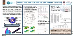
C Fichera G Vallone P Ferracin M Guinchard Ó Sacristán Outline MQXF and Nb 3 Sn cable Test campaign planning Cable stack production Experimental results Conclusion 17Nov17 ID: 1015023

nb3sn cable accelerator rutherford cable nb3sn rutherford accelerator characterization nov experimental results load radial type strain relationship azimuthal stack

Share:

Link:

Embed:

Download Presentation from below link

Download Presentation The PPT/PDF document "Mechanical behavior of MQXF cable stacks..." is the property of its rightful owner. Permission is granted to download and print the materials on this web site for personal, non-commercial use only, and to display it on your personal computer provided you do not modify the materials and that you retain all copyright notices contained in the materials. By downloading content from our website, you accept the terms of this agreement.


Presentation Transcript

1. Mechanical behavior of MQXF cable stacks at room temperatureC. Fichera, G. Vallone, P. Ferracin, M. Guinchard, Ó. Sacristán

2. OutlineMQXF and Nb3Sn cableTest campaign planningCable stack productionExperimental resultsConclusion17-Nov-172Workshop on Nb3Sn Rutherford cable characterization for accelerator magnets

3. IntroductionThe coil behavior is a crucial information for the structural assessment of magnets and prediction of conductor performance:Mechanical properties at room and cryogenic temperatureThermal properties from room temperature down to cryogenicKnowledge of coil properties shows uncertainty:Different testing configurations (constrains, measurement technique)Different cable configurations (epoxy, fiberglass, Mica, etc.)Large scattering in material properties (thermal/mechanical)In FE models bad numerical-experimental comparison with impregnated MQXF coils.17-Nov-173Workshop on Nb3Sn Rutherford cable characterization for accelerator magnets

4. Test campaign planning17-Nov-174Workshop on Nb3Sn Rutherford cable characterization for accelerator magnetsWhere the mismatch between the experimental and the numerical results with real coils comes from?Tolerances (as for dummy coils)Measurement technique (as for dummy coils)Coil propertiesHow to reproduce the coil response in FE model?Macroscale approach(Solid block)Sub-modelling approachMicroscale approachExperimental TestSampleTemperatureLoading DirectionMeasurementsFree CompressionPIT 10-stackReacted+Impregnated300 KAzimuthalEyy, εyy, νyx, νyz RadialExx, εxx, νxy, νxz LongitudinalEzz, εzz, νzx, νzy 77 KAzimuthalEyy, εyy, νyx, νyz RadialExx, εxx, νxy, νxz LongitudinalEzz, εzz, νzx, νzy RRP 10-stackReacted+Impregnated300 KAzimuthalEyy, εyy, νyx, νyz RadialExx, εxx, νxy, νxz LongitudinalEzz, εzz, νzx, νzy 77 KAzimuthalEyy, εyy, νyx, νyz RadialExx, εxx, νxy, νxz LongitudinalEzz, εzz, νzx, νzy Courtesy by M. Daly

5. Cable stack17-Nov-175Workshop on Nb3Sn Rutherford cable characterization for accelerator magnetsReaction MouldImpregnation Mould10-Cables stackCutting toolThe study of the mechanical properties must be carried out on representative samples of the coil.Dedicated moulds for reaction and impregnation (1.2% width and 4.5% thickness growth considered);Fiberglass: TEX 636, ceramic binder: CTD-1202, epoxy: CTD-101K;18.7×18.85×150 mm long cable stack (RRP coil 106, PIT coil 203).ParameterUnitMQXFStrand diametermm0.85Fabrication processRRP, PITNumber of filaments132, 192Nominal sub-element diameterum<50RRR after full heat treatment>150Cu/non-Cu1.2Minimum Ic (15 T, 4.222 K)*A361Number of strands40Cabling degradation%<5Cable bare widthmm18.15Cable bare mid-thicknessmm1.525Keystone angleDeg.0.5520 mmDedicated and validated test bench equipped with 8 LVDTs to measure:Stress-strain relationship in all directions;Transverse-longitudinal strain relationship.LVDTs longitudinalLVDTs transversal

6. Experimental tests17-Nov-176Workshop on Nb3Sn Rutherford cable characterization for accelerator magnetsDifferent test typologies to study the cable stack behavior during loading, unloading and cycling phases.Type A: Single step load and cyclingType B: Single step load (no cycling) + load holdingType C: Multistep load and cycling

7. Experimental results – Azimuthal (1)17-Nov-177Workshop on Nb3Sn Rutherford cable characterization for accelerator magnets8 tests in azimuthal direction have been performed.3 of type A: Single step load and cycling4 of type B: Single step load (no cycling)1 of type C: Multistep load and cyclingSignificant initial deformation:Cable stack compactionPre-load does not reduce data dispersionCycling phases look very similar

8. Experimental results – Azimuthal (1)17-Nov-178Workshop on Nb3Sn Rutherford cable characterization for accelerator magnets8 tests in azimuthal direction have been performed.3 of type A: Single step load and cycling4 of type B: Single step load (no cycling)1 of type C: Multistep load and cyclingSignificant initial deformation:Cable stack compactionPre-load does not reduce data dispersionCycling phases look very similar

9. Experimental results – Azimuthal (2)17-Nov-179Workshop on Nb3Sn Rutherford cable characterization for accelerator magnetsSplitting the curves in three phases simplifies the data analysis:First loading phaseUnloading cyclic phaseReloading cyclic phase

10. Experimental results – Azimuthal (3)17-Nov-1710Workshop on Nb3Sn Rutherford cable characterization for accelerator magnetsBy definition, the material stiffness is the slope of the stress-strain curve:If K is constant, linear elastic assumption is valid and K is known as elastic modulus or Young’s modulus (E).  

11. Experimental results – Azimuthal (3)17-Nov-1711Workshop on Nb3Sn Rutherford cable characterization for accelerator magnetsBy definition, the material stiffness is the slope of the stress-strain curve:If K is constant, linear elastic assumption is valid and K is known as elastic modulus or Young’s modulus (E).  

12. Experimental results – Azimuthal (3)17-Nov-1712Workshop on Nb3Sn Rutherford cable characterization for accelerator magnetsCable stack stiffness slightly increases every cycle

13. Experimental results – Azimuthal (3)17-Nov-1713Workshop on Nb3Sn Rutherford cable characterization for accelerator magnetsCable stack stiffness slightly increases every cycleThe cable stack stiffness is strongly depended by the stress level.Elastic assumptions are not recommended to reproduce this behavior.

14. Experimental results – Azimuthal (4)17-Nov-1714Workshop on Nb3Sn Rutherford cable characterization for accelerator magnetsYZXXZThe relationship between the vertical and lateral deformations is commonly defined by:If ν is constant, linear elastic assumption is valid and ν is known as Poisson’s ratio.  

15. Experimental results – Azimuthal (4)17-Nov-1715Workshop on Nb3Sn Rutherford cable characterization for accelerator magnetsYZXXZThe relationship between the vertical and lateral deformations is commonly defined by:If ν is constant, linear elastic assumption is valid and ν is known as Poisson’s ratio. 

16. Experimental results – Azimuthal (4)17-Nov-1716Workshop on Nb3Sn Rutherford cable characterization for accelerator magnetsLongitudinal-Azimuthal strain relationship:

17. Experimental results – Azimuthal (4)17-Nov-1717Workshop on Nb3Sn Rutherford cable characterization for accelerator magnetsLongitudinal-Azimuthal strain relationship:Radial-Azimuthal strain relationship:

18. Experimental results – Radial (1)17-Nov-1718Workshop on Nb3Sn Rutherford cable characterization for accelerator magnets6 tests in radial direction have been performed.3 of type A:Single step load and cycling3 of type B:Single step load (no cycling)

19. Experimental results – Radial (1)17-Nov-1719Workshop on Nb3Sn Rutherford cable characterization for accelerator magnets6 tests in radial direction have been performed.3 of type A:Single step load and cycling3 of type B:Single step load (no cycling)

20. Experimental results – Radial (1)17-Nov-1720Workshop on Nb3Sn Rutherford cable characterization for accelerator magnets6 tests in radial direction have been performed.3 of type A:Single step load and cycling3 of type B:Single step load (no cycling)Stiffness slightly increases every cycle

21. Experimental results – Radial (1)17-Nov-1721Workshop on Nb3Sn Rutherford cable characterization for accelerator magnets6 tests in radial direction have been performed.3 of type A:Single step load and cycling3 of type B:Single step load (no cycling)The cable stack stiffness is strongly depended by the stress level.Elastic assumptions are not recommended to reproduce this behavior.Cable stack delamination at low stresses.Stiffness slightly increases every cycle

22. Experimental results – Radial (2)17-Nov-1722Workshop on Nb3Sn Rutherford cable characterization for accelerator magnetsLongitudinal-Radial strain relationship:XZYYZ

23. Experimental results – Radial (2)17-Nov-1723Workshop on Nb3Sn Rutherford cable characterization for accelerator magnetsLongitudinal-Radial strain relationship:XZYYZ

24. Experimental results – Radial (2)17-Nov-1724Workshop on Nb3Sn Rutherford cable characterization for accelerator magnetsLongitudinal-Radial strain relationship:Azimuthal-Radial strain relationship:Cable stack delamination

25. Experimental results – Radial (2)17-Nov-1725Workshop on Nb3Sn Rutherford cable characterization for accelerator magnetsLongitudinal-Radial strain relationship:Azimuthal-Radial strain relationship:

26. Experimental results – Radial (2)17-Nov-1726Workshop on Nb3Sn Rutherford cable characterization for accelerator magnetsLongitudinal-Radial strain relationship:Azimuthal-Radial strain relationship:

27. Experimental results – Longitudinal17-Nov-1727Workshop on Nb3Sn Rutherford cable characterization for accelerator magnets5 tests in radial direction have been performed.2 of type B:Single step load (no cycling)3 of type C:Multistep load and cycling

28. Experimental results – Longitudinal17-Nov-1728Workshop on Nb3Sn Rutherford cable characterization for accelerator magnets5 tests in radial direction have been performed.2 of type B:Single step load (no cycling)3 of type C:Multistep load and cycling

29. Experimental results – Longitudinal17-Nov-1729Workshop on Nb3Sn Rutherford cable characterization for accelerator magnets5 tests in radial direction have been performed.2 of type B:Single step load (no cycling)3 of type C:Multistep load and cyclingDecreasing above 100 MPa due to delaminationStiffness slightly increases every cycle

30. Experimental results – Longitudinal17-Nov-1730Workshop on Nb3Sn Rutherford cable characterization for accelerator magnets5 tests in radial direction have been performed.2 of type B:Single step load (no cycling)3 of type C:Multistep load and cyclingDecreasing above 100 MPa due to delaminationDecreasing above 100 MPa due to delaminationStiffness slightly increases every cycleThe cable stack stiffness is strongly depended by the stress level.Elastic assumptions are not recommended to reproduce this behavior.Cable stack delamination at low stresses.Cable stack length could affect the results.

31. Experimental results – Longitudinal17-Nov-1731Workshop on Nb3Sn Rutherford cable characterization for accelerator magnetsAzimuthal-Longitudinal strain relationship:ZXYYX

32. Experimental results – Longitudinal17-Nov-1732Workshop on Nb3Sn Rutherford cable characterization for accelerator magnetsAzimuthal-Longitudinal strain relationship:ZYXXYCable stack delaminationBRRP106Z6

33. Experimental results – Longitudinal17-Nov-1733Workshop on Nb3Sn Rutherford cable characterization for accelerator magnetsAzimuthal-Longitudinal strain relationship:ZYXXY

34. Experimental results – Longitudinal17-Nov-1734Workshop on Nb3Sn Rutherford cable characterization for accelerator magnetsAzimuthal-Longitudinal strain relationship:Radial-Longitudinal strain relationship:Cable stack delamination

35. Experimental results – Longitudinal17-Nov-1735Workshop on Nb3Sn Rutherford cable characterization for accelerator magnetsAzimuthal-Longitudinal strain relationship:Radial-Longitudinal strain relationship:

36. ConclusionAn extended test campaign has been carried out at CERN to study the overall behavior of impregnated MQXF cable stacks.Stress-strain relationships have been analyzed in free compression tests.In all directions (X,Y,Z) the cable stack shows strongly not linear elastic behavior.The experimental results give information about the cable stack behavior and different inputs how to reproduce it.17-Nov-1736Workshop on Nb3Sn Rutherford cable characterization for accelerator magnetsNextWhat about PIT cable?What about cryogenic temperatures?What about thermal properties?

37. Thank you

38. Experimental results17-Nov-1738Workshop on Nb3Sn Rutherford cable characterization for accelerator magnetsAzimuthalRadialLongitudinal

39. Experimental results17-Nov-1739Workshop on Nb3Sn Rutherford cable characterization for accelerator magnetsAzimuthalRadialLongitudinaldσ/dεεZ/εYεX/εYdσ/dεεZ/εXεY/εXdσ/dεεY/εZεX/εZ(GPa)(GPa)(GPa)First Loading5÷200.05÷0.20.1÷0.45÷250.05÷0.15~0.210÷25~0.160.2÷0.3Cyclic Unloading10÷500.05÷0.20.2÷0.55÷400.1÷0.2N/A10÷70~0.20.2÷0.3Cyclic Loading10÷350.05÷0.20.2÷0.55÷300.05÷0.15N/A10÷35~0.20.2÷0.3Data from literature:Summary of the test campaign:AzimuthalRadialLongitudinalFirst LoadingCyclic UnloadingCyclic Loading