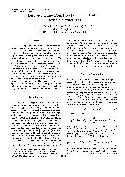
/
Proceedings of the American Control Conference Chicago Illinois June  Discrete Time PointtoPoint Proceedings of the American Control Conference Chicago Illinois June  Discrete Time PointtoPoint

Proceedings of the American Control Conference Chicago Illinois June Discrete Time PointtoPoint - PDF document

sherrill-nordquist
sherrill-nordquist . @sherrill-nordquist
Follow
495 views
Uploaded On 2014-12-27

Proceedings of the American Control Conference Chicago Illinois June Discrete Time PointtoPoint - PPT Presentation

A1Masoud 1 ShihYu Chu 2 Tarunraj Singh a School of Engineering SUNY at Buffalo Buffalo New York 14260 Abstract The primary objective of this work is to investigate lin ear time invariant systems undergoing rest to rest ma neuvers in a finite time us ID: 30239

A1Masoud ShihYu Chu

Share:

Link:

Embed:

Download Presentation from below link

Download Pdf The PPT/PDF document "Proceedings of the American Control Conf..." is the property of its rightful owner. Permission is granted to download and print the materials on this web site for personal, non-commercial use only, and to display it on your personal computer provided you do not modify the materials and that you retain all copyright notices contained in the materials. By downloading content from our website, you accept the terms of this agreement.


Presentation Transcript

of the American Control Conference Chicago, Illinois • June 2000 Time Point-to-Point Control of Flexible Structures A1-Masoud 1 Shih-Yu Chu 2 Tarunraj Singh a School of Engineering SUNY at Buffalo, Buffalo, New York, 14260 The primary objective of this work is to investigate lin- ear time invariant systems undergoing rest to rest ma- neuvers in a finite time using the discrete time domain approach. Using a given sampling period, the govern- ing equations of linear systems are first discretized into Introduction The control of physical systems with digital computers is becoming more popular in industry. Many new digi- tal control applications are being stimulated by micro- processor technology with applications such as automo- biles and household appliances. Among the advantages of the digital logic for control are the increased flexi- bility of the control programs and the decision-making or logic capability of digital systems. Systems requir- ing a change system are transformed from continuous time do- main to discrete time domain with different sampling periods. The system differential equations are decou- pled using similarity transformation resulting in a set of algebraic equations. The resulting system is first solved assuming sub-optimal polynomial control profile at different sampling periods. To achieve an optimum control sequence ui+l,* Problem Formulation In point-to-point control problems, the vector y(t) is completely specified at two different instants of time, tl and the control input ~!(t) required to achieve these end conditions is to be determined. Let N = (t2- the total sampling interval, and the boundary conditions = A_y(t) + B u(t) The solution of Eq. (1) is = ¢(t - to)y_(to) + ¢(t - r)Bg(r)dr y(t0) is the initial state. The input t = ¢(t-kAT)y_(kAT)+ O(t-r)Bdr u_(kAT) (3) describes the state vector y(t) at all times be- tween the sampling instants (k + 1)AT, for k = 0, 1,2 .... ,N-l(for simplicity, T will replace ' . I For numerical simulations, it is more convenient to describe y(t) only at the sampling instants. Let t = (k + 1)T, then Eq. (3) becomes the discrete state equations of the sampled-data system. _g(k + 1)T = Ady(kT) + Bdu(kT) (4) Ad = e AT the state transition matrix of A, and Bd ®(T) = f? ~(T-r)Bdr the discrete control influence matrix• The most straightforward method of solving Eq. (4) under the boundary con- straints is by recursion (Kuo 6). Using the transition terms property = ~(T)O(T)... ~(T) = Ad N, solution of Eq. (4) is AdNy(0) + E full controllability, a unique transformation can be found such that the discrete state equations Eq. (4), with some rearrangement, can be re-written in Jordan canonical form (Miu 5). x(k + 1)T = J + (6) where, = diagAj Aj is the Jordan block asso- ciated with the pole multiplicity of similarity transformation J = P-1AdP transforms the discrete system matrix Ad into Jordan canonical form J, which is nearly a diagonal matrix• The columns of transformation matrix P are the eigenvectors of Ad. The control influence matrix Bd and the end condi- tions are transformed accordingly• F = P-1Bd , x_(0) = P-iV(0) , = P-~y_(NT) As an example, consider a Jordan block A1 defined above) associated with a pole zt which has a multi- plicity of four, so the state equation is 1) = 1 0 00 0zl1 0 0 zt is possible to find the state transition matrix in a systematic manner with almost the same ease as in the case of a diagonal matrix. Notice that the last state equation in Eq. (8) is entirely decoupled from the other equations, thus the fourth element of the vector ~ can be found as x4(k) = x4(k) in the third state equation, solve for xa(k) ZlX3(k ) + x4(k ) -~- zlx3(lg ) + ZlkX4(0) (9) (9) can now easily be solved for x3: x3(k) = Continuing with the same process, the solution of xl (k) is l(k) = - - 2) zk-3x4( 0)1 (11) matrix form, the state transition equation is written as ~(k) = J~ x(0) where - kik-1)(k-2)z-Zn 1 kz~ "-1 1 2 3! 1 ! -2 1 Zl | (12) J~ = Zlk 0 1 k 1 o the same recursive approach, the solution of Eq. (6) can be derived as = + E jm = , AJ y = z~ v Nzf' 1 0 0 0 0 0 0 0 0 N(N--1)'"(N--mi+2) z--m j+l •.. (mi_l)! J .., 0 ". 0 " ' 2~ z3 .. 1 "" 1 Solution of the Discrete Open-Loop Control Under the assumption that the control input represented as a linear combination of some indepen- dent components, the control input can be written as = ¢ff (KT)h (15) C T(KT) and h are the assumed control profile independent variable vector and their coefficients re- spectively.Using Eq. (15), Eq. (13) can be rewritten as - = N).A N) = E JY-k-lF¢-- T(kT)" a control in- k=0 put specified in Eq. (15) and a given end con- ditions (16) can be solved for the unknown coefficients : Z-i(T, N)x(NT) - (17) Optimal Solution of the Discrete Open-Loop Control The optimal control problem is to find the control _u~ on the interval 0, N that drives the system along a trajectory x_~ such that a given performance index is Suppose we are concerned with minimizing the power of a single input problem, that is E x_(k + J + Because the constraint equation is specified at each time k in the interval of interest, a Lagrange multiplier is required at each time step, i.e. each constraint has an associated Lagrange multiplier (~ E find the optimal control profile drives the system from a given initial state x(0) to the desired ~(N) over the interval 0, N while minimizing Eq. (18), define the Hamiltonian as k = u~ + + Fuk (19) the set of necessary conditions to be satisfied are given by (Lewis 7). k equation: x-k+l O.~..k+ 1 -- J-~.-k + 0H k co-state equation: A k -- -- -- JT~k+ 1 (20) X_k 1 T stationarity uk = -~F ~k+l Eq. (20) are a set of linear homogeneous difference equations. We can rewrite the costate equations as = (Jr)mA_k+,~ (21) m = N - k, then the solution of ~k can be repre- sented by the final co-state vector aN as hk = (jT)N-khN Eq. (22) into Eq. (21) with k = k+l, solve for the optimal control profile in terms of the final co- state vector as = --21--FT(jT)N-k-lh(N) = $_T~N Sensitivity to System Parameters The design of accurate control system in the presence of significant uncertainty requires the designer to seek a robust system. The plant model will always be an inaccurate representation of the actual physical system because of parameter changes, unmodeled dynamics, time delays, sensor noise. The goal of robust system design is to retain assurance of system performance in spite of model inaccuracies and changes. If we want to reduce the influence of the uncertainty of the parame- ters on the final states , we can include the sensitivity to these parameters inside the state equations. From Eq. (6), the relation of the pole zj associated with the state multiplicity 1 in Jordan canonical form is ) Eq. (24) with respect to z, the sensitiv- ity equation is obtained as (25) + j~ , dz dz new = Eq. (25) becomes the new discrete state equation is similar to Eq. (6) and the combined system can be represented as ~(k + 1) = J ~(k) + F~(k) (27) where, = 0 0 0 z2 o o (28) 0 0 z3 0 0 1 0 z2 0 0 1 0 z3 J and !(k) = x(k),,×l_ ,(~Sd~dz ,;×1 T ,~ = r~x~ _09 ×~ iT, applying similarity transformation, the Jordan canon- ical form of Eq. (27) and the corresponding optimal and sub-optimal control profiles can be found using the same procedure outlined above. Simulation and Numerical Examples A systematic procedure to obtain the control profile for a system undergoing a rest-to-rest maneuver in discrete time domain is presented in this section, the results are then compared with those of the corresponding contin- uous system. The solution for the control parameters is obtained for a plant with a repeated poles using var- ious sampling periods. Both sub-optimal and optima! solutions are presented. The effect of the uncertainty in the system's parameters is addressed by introducing the sensitivity equations and the optimal control pro- file for this case is derived. The following general pro- cedure is adapted throughout the this paper : 1. Check the rank of the system controllability matrix. It must be fully controllable system, 2. Discretize the system using Eq. (4), 3. Find the Jordan canonical form of the discrete state equation as shown in Eq. (6) and the cor- responding generalized eigenvectors P associated with it, 4. Transform the system control influence matrix 13 and the boundary conditions using Eq. (7), 5. Assume a control profile = ¢_T(KT)h, is a vector of linearly independent components and use Eq. (17) to solve for ~. 1: Consider the continuous time transfer function = 1/s2(s ~ + s.t. : = 1, all other end conditions are zero at = -4~r t.f = 0. This is an undamped system with one rigid body mode and one flexible mode and natural frequency of 1 rad/sec. Using Eq. (6) for a sampling period of 0.1 equivalent Jordan Canonical form of the system J = .9950+.0998~ 0 0 0 0 .9950- .0998z 0 0 0 0 1 1 0 0 0 1 the new control influence matrix and end con- ditions are respectively: F = .099 + .005~ .099- .005~ .050 .100 r , x(0) = 0 0 0 0 T , x(N) = 0 0 10 0 T. Assuming the control profile has a polynomial form given by = _¢T(KT)~, (-kT)(-kT) ~ 3 . Solving for the control profile parameters using Eqs. (15), (16) and (17), we have = -0.0188 0.0501 .0114 0.0006 ,and the associated control profile is -0.019 + 0.050(k) + 0.0006(k) 3 (30) To find the optimal control profile, the control profile is assumed to be a function of the systems eigenvalues. Because we have a repeated poles, the equivalent trans- formation must he done by introducing the generalized eigenvectors as shown in Eq. (23): and the correspond- ing control profile is z~ N-~-~ (g- 1 - k)z~ N-~-~ N_,_ ~ Z~V_,_~ )~, T (31) where z~ is the repeated pole . For this system, the vector of the optimal control profile parameters ~ can be evaluated by Eq. (17) as = 10 -~ -4.4 .07 .02 + .7, .02 - .7, T (32) this sampling period the control profile is u(k)=~0 ×z+~lP×Z -'+~×z~+~3×z~ (33) where p = N - 1 - k and N is the number of sampling periods. The system response for the control input given by Eq. 30 is shown in Fig. (1). To compare the discrete system results with the continuous system re- sponse, the simulations for the system given in 4 are also presented in the same figure. Plots of the optimal control profile and the system response are shown in Figs. (1) and (2). Example 2: To examine the robustness of the system response to the parameter uncertainty in the flexible mode poles z~ and z3, the same system as considered previously will be discussed here, this time with the =~lem co~lmi protiln -0.O4 y"llRl-y'14n)~O 1 y(O~y,(O) ,,.y,,lO) ~y~(O) ~0 -O,ti rylltem rod ~ofil~ ~,.-0.0,0=~ I ~ =-0.011379 k =-ti,00061170 0,04 a 4 -0.~ -0.~ 10 time secl Sampl*ng Inlerwd pefiod,.O,l y(N)-l,y'(N}-O , • Y'(NI=y'(N)"O ylOl.Y'lOl.Y'(O~y~(O).,O _O.So~Y(OJ'ylO)'y (O~y (~'0 ~- 1: open-loop control of example 2 using polyno- mial input, T = 0.1 00a • 06 0 2o 40 8O 100 ~mpiing Inler~d= N |lWItie t ')/{NTI=Yy~!NT) "Y"INT) "0 aamO(in~ p*rtcxi ,,,~, (O)=q'lO),,,y'(O)=y"O)..O 20 40 60 ~ 100 120 Sarnpting N ' 2: minimum power control and system response of example 2 , T = 0.1 of sensitivity equations. As in the previous example, a sampling period of 0.1 sec is used. Use Eq. (27) and similarity transformation to examine the influence of parameter uncertainty of the flexible mode poles z2 and z3. The resulting Jordan canonical for this system has 3 poles each of multiplicity 2. Following the same procedure of the previous example, the optimal control profile is assumed to be = ~0 × zf + Alp × z -1 + ~2 × z~ + ~3p × z~ -1 + ~4 × z~ + ~p × z~ -1 (34) p = N - 1 - k and zi, )q are respectively the elements of ¢(k) : z~ -~-~ (N - 1 - k)z~ -~-~ -~-~ (N 1 - -2-~ ~-1-~ (N - 1 - k)z~-~-~ ~ (35) -4.57 e -2 7.31 e -4 -8.56 e -5 + 1.14 e-hz -8.56 e -~ - 1.14 T e -3 + 6.70 e -3 - 6.70 e-3t (36) I ..... of the optimal control profiles with and with- out considering the sensitivity equations are shown in Fig. (3) for a sampling period T = 0.1 natu- ral frequency of 1 rad/sec. In Figs. (4), a system with natural frequencies :E5% of the original is subjected to the same optimal control input . It shows that the sys- tem performance is robust to the model inaccuracies and changes. The system response at the final state for each frequency is zoomed up on the right subplots. o~ -o -o o, -o o~ 3: minimum power control profiles of example 2 with sensitivity, sampling period T = 0.1 racYsec O' 0 50 100 150 200 ~1.00 radsE¢ 50 100 150 L~O =0.~ tad/o: ~ ,~ Int~aJ,~N rad/r,~z¢ 1.~ 1.01 150 200 ~1.00 racY~,ec 1.02 1.01 ~ / , 150 200 0~=0.95 ra~sec 1.02 150 200 Samp~i N Intarv~ N 4: system response of example 2 with variation of natural frequency The focus of this paper was on solving the point to point control problem in discrete time domain and com- pare it with the results obtained by (Miu & Bhat 5) and other researchers for continuous time systems. They used a finite Laplace transform technique for solv- ing the benchmark problem with spring-mass system in continuous time. The same example was used in this study in order to compare the control results in discrete time domain. The original continuous system were dis- cretized and decoupled by using the similarity trans- formation which change the difference equations into a set of algebraic equations that can be easily solved. The finite time Laplace transform used in continuous time system by (Miu & nhat 5) was replaced by a method which can be called a finite Z transform. For this class of problems, the results obtained were com- patible with the continuous time counterparts. As the sampling period was decreased, the behavior of the sys- tem approaches that of the continuous time system. The shape of control profile depends on the position of the poles, which in turn depends on the sampling period used. The sensitivity analysis shown in example 2, illustrates that the added states based on the parameters of the system can significantly reduce the influence of uncer- tainty of identification of the parameters. The pro- posed control system exhibits the desired performance despite the presence of plant uncertainty. Juang J.N. al., Closed form solution of for Feedback Problems with Terminal Constraints, of Guidance and Control Vol. 8,,No. 1 Jan-Feb, pp. 127-135, 1985. 2 Singh, G. Kabama, et Planar, Time-Optimal , Rest-to-Rest Slewing Maneuver of Flexible Space craft,Journal Guidance and Control Vol. 12,,No. 1 pp.71-81, 1989. Theory of Machines and Mechanisms, Vol.3, pp. 1489-1494, 1987. 3 Cannon, R. al, Initial Experiments on the End Point Control of Flexible one Robot, J. of Robotics Research, Vol. 3, pp 62-75, 1984. 4 Miu, D. K., Bhat S. P., Point to Point Positioning Control of Flexible Structures, J. of Dynamic Systems, Measurement, and Control, Vo. 112, pp. 667-674 , 1990. 5 Miu, D. K., Bhat S. P., of Point to point Control Problems Using Laplace Transform Technique, J. of Dynamic Systems,Measurement, and Con- trol, Vol. 113, pp. 425-431 , 1991. 6 Kuo, B.C., Control Systems,Saunders Publishing. 1992. 7 Lewis, F. L.,Syrmos, V. L., Control edition. John Wiley & Sons, Inc. 1995.