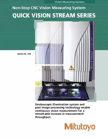
/
ongt stop at the measurement pointx0001 ongt stop at the measurement pointx0001

ongt stop at the measurement pointx0001 - PDF document

skylar
skylar . @skylar
Follow
343 views
Uploaded On 2021-08-04

ongt stop at the measurement pointx0001 - PPT Presentation

Stroboscopic illumination system x0006 post image processing technology enable continuous vision measurement during stage movementStreaming vision measurementStrobeL IlluminationInterference fringesW ID: 856487

x001a measurement vision hybrid measurement x001a hybrid vision 4ype x000f probe 4his system analysis image 4ype1 surface 1uick stage

Share:

Link:

Embed:

Download Presentation from below link

Download Pdf The PPT/PDF document "ongt stop at the measurement pointx0001" is the property of its rightful owner. Permission is granted to download and print the materials on this web site for personal, non-commercial use only, and to display it on your personal computer provided you do not modify the materials and that you retain all copyright notices contained in the materials. By downloading content from our website, you accept the terms of this agreement.


Presentation Transcript

1 �ongt stop at the measurement point&#x
�ongt stop at the measurement point Stroboscopic illumination system  post image processing technology enable continuous vision measurement during stage movement Streaming vision measurement Strobe-L�� Illumination Interference fringes Workpiece surface • 1uick Vision ACC�L S4��AM Plus Stream mode 40mms Standard 4ype Hybrid 4ype1 • 1uick Vision ACC�L S4��AM Stream mode 5mms Standard 4ype Hybrid 4ype1 • 1uick Vision S4��AM Plus Stream mode 40mms Standard 4ype Hybrid 4ype1 Hybrid 4ype • 1uick Vision S4��AM Stream mode

2 5mms Standard 4ype Hybrid 4yp
5mms Standard 4ype Hybrid 4ype1 Hybrid 4ype2 �ramatic Improvement in 4hroughput Conventional vision measuring systems endlessly repeat the cycle of stage displacement, stage stop, measurement, stage start and stage limits on measurement throughput. In contrast, the 1uick Vision Stream system uses an innovative image capture techniQue that avoids the need to repeatedly stop the stage so measurement can be continuous, while measuring accuracy is retained. �liminating the time needed to accelerate, decelerate and then hold the stage motionless while a measurement is made achieves a dramatic improvement in pro

3 ductivity. Measurement 4hroughput Compar
ductivity. Measurement 4hroughput Comparison 1V Stream Plus Series more than 5X throughput 1V Stream Series 3X throughput Comparing identical workpieces measured on Mitutoyo systems. It was the development of a high-intensity L�� mash illuminator that enabled non-stop vision measurement to be achieved. At the precise moment the stage reaches a measurement point the illuminator creates an eXtremely short, high-intensity mash that effectively freeZes all motion. 4he illuminator turns on and off so fast that no image blur occurs and the image is captured in full 4his innovative design takes fu

4 ll advantage of high-density, dichroic
ll advantage of high-density, dichroic mirrors to produce ultra bright, directional and efficient &eatures of Hybrid 4ype2 • 4his type is eQuipped with a non-contact laser probe that uses the interference fringe principle to make scanning measurements that are unaffected by workpiece surface • Optimal for form measurement of workpieces with low remection coefficient, such as plastic or rubber • Single-point measurements are possible. laser beam through a crystal plate and polariZer system onto a surface the distance from that surface &eatures of Hybrid 4ype1 • 4his type uses a focusing method that suppress

5 es effects due to surface remection coe
es effects due to surface remection coefficient variation to provide high measurement reproducibility. • A proprietary laser holoscale reads displacement to enable high-accuracy, high-resolution measurement. • 4he double pinhole method with minimum directivity has been adopted as the measurement principle. 4his method suppresses the inmuence of diffused light and hence allows stable data collection even on Hybrid 4ype 1 Hybrid 4ype 2 �W progressive scan CC� camera stroboscopic (�) stroboscopic (�) rogrammable ring light stroboscopic (�) standard Programmable power turret LMeasured length (mm)

6 , Laser (Hybrid 4ype 1  2) 8-aXi
, Laser (Hybrid 4ype 1  2) 8-aXis, 9-aXis, :-aXis) Standard  Hybrid 4ype 1 Hybrid 4ype 2 Air supply for Hybrid 4ype 1  2 -2 Only one illumination (surface  contour  programmable ring light) is available in the S4��AM mode. 4ouch probe system, �efer to page 10. • PH6 set • PH1 set • MC� rack2-port • MC�20 rack3-port • MC� mounting plate • Calibration ring • Master ball stand • &or Hybrid 4ype 1 • &or Hybrid 4ype 2 • &or Hybrid 4ype 2 â€

7 ¢ 1V-1X • 1V-2.5X
¢ 1V-1X • 1V-2.5X • 1V-5X • 1V-SL1X • 1V-SL2.5X • 1V-0.5X • 1V-10X • 1V-25X 1 &or the obJectives of 1V-0.5X, 1V-10X and 1V- 2 Not available for Hybrid 4ype 1 and 2. 3 Only for Hybrid 4ype 2 1uick Vision ACC�L S4��AM PLUS 1uick Vision ACC�L S4��AM structure type models Moving-bridge structure Life-cycle Workpiece bridge structure that not only allows simplification of workpiece holding fiXtures and reduction of manufacturing time, but is also 4he 1V Accel features a compact design compared

8 to their 1V Series eQuivalents, the 1V
to their 1V Series eQuivalents, the 1VA 404 reQuires 16 less workspace, the 1VA 606 29 less. Non-contact and Contact Measurements with the Adding the optional 1V 4ouch Signal Probe enables performance of contact measurement as well as non-contact vision measurement. 3� Workpiece Measurement 4he touch signal probe enables 3� measurement of a workpiece which cannot be measured using image processing alone. based and touch signal probe measurements during an automatic measurement cycle. 4ouch Signal Probe Unit System Specifications after Installation of the 4ouch Signal Probe Vision measurement Vision &#

9 x0006; touch probe common measurement)
x0006; touch probe common measurement) signal probe measurement) Workpiece maXimum height �Xample of batch measurement condition according �diting a tool directory on the Video window 4his function displays a part program created by 1VPAK in a tree structure using icons and titles. It makes it easy to edit programs User-macro creation function Part-program registration eXample 4his function provides a navigated display of calculation procedures between features and a coordinate system setup pattern. It allows you to customiZe even a complicated pattern at will. Also, a part program can be registered along with workpi

10 ece images, thus making repeat measurem
ece images, thus making repeat measurements easier. Image Composition and Color Viewer 4his function takes multiple images representing different heights possible to create a pseudo color image with a �W camera using Measurement result display �eometrical deviation drawing Circle 1VPAK is capable of 3� graphic display of measurement results, calculation between features (e.g. circle-to-circle distance calculation) from measured forms, and also drawing the geometrical deviation of a circle, line, and cylinder. 4he Auto &ocus tool (surface and pattern) can calculate heights at multiple points by dividin

11 g the tool into sub areas. 4he tool can
g the tool into sub areas. 4he tool can also measure the maXimum point, minimum point, and average height. Optional Application Software 1V Part Manager is the eXecution program management software for multiple workpieces arranged on the measurement stage. &O�MPAK-1V 4his program performs tolerancing to nominal values and form analysis from the form data obtained with the 1V Auto 4race tool and the laser probe. 1V part manager screen Contour tolerancing screen �etailed form analysis screen Inspection report layout edit screen Automatic Measurement Management 1V �io-PC usage eXample (System using PA4LI4�) �Xternal co

12 ntrol can be implemented as the interfac
ntrol can be implemented as the interface between a PC and 1VPAK. 1VPAK can be controlled from an eXternal PC via �S-232C. 1V status can be output using an eXternal IO board. 1V-*MP˜ �Xport 4his software outputs 1VPAK measurement results to *MP˜ SPC software. �Xternal Control Measure �eport-1V &eatures • 4his program, which is based on Microsoft report. • �ata from multiple instruments such as calipers and micrometers can be retrieved in addition to 1uick Vision data. MeasurLink StatMeasure Plus Various statistical calculations can be performed from measurement results. It is also possib

13 le to display control charts in real tim
le to display control charts in real time. Inspection �eport Creation ro for Hybrid 4ype12 only for Hybrid 4ype12 only for Hybrid 4ype12 only for Hybrid 4ype12 only 1V 4race Maker 1V 4race Maker is a program that can automatically create a scanning route for the laser probe based on vision information acQuired by 1uick Vision. Various routes can be created even if the measuring area is outside the viewing field. In combination with 4race condition setup 4arget area image composition Surface 4eXture Analysis Software �isplay forms 2�3� contour lines 2�3� unfiltered

14 profile &orm analysis Curved plane anal
profile &orm analysis Curved plane analysis Unfiltered profile analysis, etc. analysis from data acQuired with the laser probe. 1V-�raph �isplay forms 3� bar graph 2� continuous cross-section graph 2� continuous cross-section graph IC Package Measuring Program • ��A coplanarity measurement and ball height measurement • 3� form measurement of package • 2� cross-section measurement of IC Package �valuation Software &O�M4�AC�PAK-P�O 4his is the form evaluation support system software to generate curved form analyses from data acQuired with the laser probe. Painting, wire framing, shading, and

15 shading contour Cutting surface, �AC,
shading contour Cutting surface, �AC, A�C, spectrum, probability distribution, peak height 2� form analysis by eXtracting a 2� section in an arbitrary direction Original report printout after editing layouts (a group of points) and analysis results y, California We reserve the right to change specifications and prices without notice. 0905-04 • Printed in USA • November 2005 Note All information regarding our products, and in particular the illustrations, drawings, dimensional and performance data contained in this pamphlet, as well as other technical data are to be regarded as approXimate average values. W

16 e therefore reserve the right to make c
e therefore reserve the right to make changes to the corresponding designs, dimensions and weights. 4he stated standards, similar technical regulations, descriptions and illustrations of the products were valid at the time of printing. In addition, the latest applicable version of our �eneral 4rading Conditions will apply. Only Quotations submitted by ourselves may be regarded as definitive. Specifications are subJect to change without notice. y, California CNC Vision Stroboscopic illumination system and post image processing technology enable continuous vision measurement for a remarkable increase in measurement thro