/
The Muon Accelerator Program The Muon Accelerator Program

The Muon Accelerator Program - PowerPoint Presentation

stefany-barnette
stefany-barnette . @stefany-barnette
Follow
408 views
Uploaded On 2016-11-29

The Muon Accelerator Program - PPT Presentation

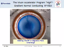
High Gradient Normal Conducting RF RampD Alan Bross US HG Workshop February 910 2011 1 Meeting the RF in Magnetic Field Challenge Outline The RF Challenge At least ID: 494762

alan bross february workshop bross alan workshop february 2011 cavity mhz amp gradient test 201 beam mta field surface

Share:

Link:

Embed:

Download Presentation from below link

Download Presentation The PPT/PDF document "The Muon Accelerator Program" is the property of its rightful owner. Permission is granted to download and print the materials on this web site for personal, non-commercial use only, and to display it on your personal computer provided you do not modify the materials and that you retain all copyright notices contained in the materials. By downloading content from our website, you accept the terms of this agreement.


Presentation Transcript

Slide1

The Muon Accelerator Program

“High”-Gradient Normal Conducting RF R&D

Alan Bross

US HG Workshop February 9-10, 2011

1

Meeting the RF in Magnetic Field ChallengeSlide2

Outline

The “RF Challenge”At least “Our” RF ChallengeCurrent Program (Where we are)

MAP’s RF Test FacilityMuCool Test Area (MTA) at FermilabSummary

Alan Bross

US HG Workshop February 9-10, 2011

2Slide3

Normal Conducting RF

R&D Issues for MAP and Present StatusMuon bunching, phase rotation and cooling requires Normal Conducting RF (NCRF) that can operate at “high” gradient within a magnetic field strength of up to approximately 6T

Required gradients (15-18MV/m) easily obtainable in absence of magnetic field

And since we are primarily considering pillbox structures, 15-18MV/m is also the max surface gradient

Alan BrossUS HG Workshop February 9-10, 2011

3Slide4

Muon Cooling Channel& RF

Alan Bross

US HG Workshop February 9-10, 2011

4Slide5

“Our” RF

ChallengeSignificant degradation in maximum stable operating gradient with applied B field

Alan Bross

US HG Workshop February 9-10, 2011

5

805 MHz RF Pillbox data

Curved Be windows

E parallel B

Electron current/arcs focused by B

Degradation also observed with 201 MHz cavity

Qualitatively, quite differentSlide6

805 PillboxPost-Mortem

Alan Bross

US HG Workshop February 9-10, 2011

6

Significant damage observed

Iris

RF coupler

Button holder

However

No damage to Be windowSlide7

201 MHz Cavity Test

Treating NCRF cavities with SCRF processes

The 201 MHz Cavity – Achieved 21 MV/m

Design gradient – 16MV/m

At 0.75T reached 10-12 MV/m

Alan Bross

7

US HG Workshop February 9-10, 2011Slide8

201 MHz Cavity Running

8

US HG Workshop February 9-10, 2011

Alan Bross

Design GradientSlide9

201 MHz Prototype

Alan BrossUS HG Workshop February 9-10, 2011

9

However, Observed no damage in cavity (

- except in coupler

)Slide10

201 MHz Cavity Coupler

Alan Bross

US HG Workshop February 9-10, 2011

10

Arcing at loop

Cu deposition on

TiN

coated ceramic RF windowSlide11

RF Breakdowns

Are not all equalNCRF conditioning (B=0), process allows for higher gradient operation (“conditioning”)

Both our 805 MHz and 201 MHz followed the conventional wisdom hereNCRF (B ¹

0), process can cause damage and require re-conditioning at lower gradient in order to reach the same gradient attainable before breakdown805 MHz cavity was

severely damaged201 MHz was “altered”At quite low B

Alan Bross

US HG Workshop February 9-10, 2011

11Slide12

RF Operation in Vacuum805 MHz Imaging

Alan Bross

US HG Workshop February 9-10, 2011

12

12

B

Hot Spot Arc forms

Cavity Energy

W=1/2 CV

2

»

1-5 joule

All goes into melting Cu

Surface Field Enhancement

Initiates the event & B focuses the e

-

current

which causes damageSlide13

Operate in Gas

m give us this optionRF cavities filled with High-Pressure H

2Paschen’s Law

Alan Bross

MAP REVIEW 24-26 August, 2010

13

Rolland Johnson

Shelter Island 2002Slide14

High Pressure H

2 Filled Cavity Work

with Muons Inc.

High Pressure Test Cell

Study breakdown properties of materials in H2 gasOperation in B field

No degradation in M.S.O.G. up to

»

3.5T

Next Test – Repeat with beam

No Difference

B=0 & B=3T

14

US HG Workshop February 9-10, 2011

Alan Bross

Well beyond gradient requirement for HCCSlide15

High Pressure H2

Filled Cavity ResultsIn Surface Breakdown Regime

Alan Bross

US HG Workshop February 9-10, 2011

15

Pit distribution fit to E

max

(ANSYS)

»

Fowler-NordheimSlide16

The MAP NCRF ProgramR&D Strategy

Technology Assessment (continuation of existing multi-pronged

program & explore new ideas

)Surface Processing

Reduce (eliminate?) surface field enhancementsSCRF processing techniques

Electro-polishing (smooth by removing) + HP H

2

O rinse

More advanced techniques (Atomic-Layer-Deposition (ALD))

Smooth by adding to surface (conformal coating @ molecular level)

Materials studies

: Use base materials that are more robust to the focusing effects of the magnetic field

Cavity bodies made from Be or possibly Mo

Magnetic Insulation

Inhibit focusing due to applied B

High-Pressure Gas-filled (H

2

) cavities

Alan Bross

US HG Workshop February 9-10, 2011

16

VacuumSlide17

Testing Queue

Primary goal is to collect a lot more data with as many test vehicles as possible (And understand/fix coupler issues) [Next 12-18 months]

805 pillbox (

modified & refurbished)Fixed coupler port and will retest

With Cu and Be windowsNew series of materials & processing (Cu) tests with ButtonsInitial test of HP button cavity with proton beam

201 MHz cavity coupler repair and

re-test

2nd HPRF beam test as needed

Rectangular box cavity with

B

ǁ

E

2nd

rectangular box cavity with B

^

E

New pillbox is near ready (

Muon’s

Inc.)

Can operate under pressure or vacuum

Has

capability to replace

end-walls (Be)

ALD

cavity

Special-purpose cavity for processing in-situ with Atomic Layer Deposition

Test MICE production 201 MHz cavity in realistic B

field [> 18 months out]

Alan Bross

US HG Workshop February 9-10, 2011

17Slide18

Recent R&D Highlights

Alan Bross

US HG Workshop February 9-10, 2011

18Slide19

Material Studies

Pillbox cavity refurbished & “Button” system

redesigned. Note: Results to date did indicate that Mo can improve performance at a given B field by somewhat more than 50% & that TiN

helped16.5MV/m ® 26MV/m

But, lots of scatter in data

Alan Bross

US HG Workshop February 9-10, 2011

19

Molybdenum buttons

(

1.7x

field enhancement factor on button surface)

New - FE

»

3Slide20

Magnetic Insulation

Although lattices that employ magnetic insulation have drawbacks with respect to the required RF power, we are studying the concept using a newly completed 805 MHz box cavity

Conceptual Design

20

US HG Workshop February 9-10, 2011

Alan BrossSlide21

Box Cavity in Solenoid

21

US HG Workshop February 9-10, 2011

Alan Bross

Max angle w/r to horizontal

»

12

0

E at 78

o

w/r to B

Max Gradient (B=0)

5

0MV/mSlide22

Box CavityPreliminary Data

Alan Bross

US HG Workshop February 9-10, 2011

22

Notes

B=0 running stable at

»

50 MV/m

Boroscopic

inspection did not indicate much damage

May elect to cut open for detailed

analysis

Follow-on

Test B

ǁ

E version of this cavitySlide23

MAP RF Test Facility

MuCool Test Area (MTA)RF power 201 MHz (5MW)

805 MHz (12 MW)Class 100 clean room4T SC solenoid

250W LHe cryo-plantInstrumentationIon counters, scintillation counters, optical signal, spectrophotometer400 MeV p beam line

Alan Bross

US HG Workshop February 9-10, 2011

23Slide24

MTA Layout

Alan Bross

US HG Workshop February 9-10, 2011

24Slide25

MTA Hall – Clean Room

25US HG Workshop February 9-10, 2011

Alan BrossSlide26

MTA Hall – Clean Room II

Alan BrossUS HG Workshop February 9-10, 2011

26

Goal for Clean room : Class 100

Achieved better than Class 10

Even with 3 people inside: Class 40

Goal for

Hall: Class 1000

Achieved Class 500Slide27

MTA Instrumentation

Alan Bross

US HG Workshop February 9-10, 2011

27

Counters

Optical Diagnostics

DAQ

RF Pickup

X-ray

Optical

Acoustic diagnostics

Planning to explore utilizing acoustic “imaging’

use instrumentation developed for COUPP Slide28

MTA Beam Line Status

Beam Line Installation

CompleteBeam Line commissioning to first beam stop.

Complete

Radiation assessment submitted to DOEFirst

beam experiments by

March

The MTA

is a

World-Class

Facility

(& Unique):

High-Power RF; High-Intensity Beam;

H

2

handling, SC Magnet

28

US HG Workshop February 9-10, 2011

Alan BrossSlide29

Testing 201 MHz Cellin realistic B

Alan Bross

US HG Workshop February 9-10, 2011

29Slide30

Summary

We have a comprehensive program aimed at developing a solution to our“RF

Challenge”The experimental program is now coming on strongly and is backed by simulation efforts.

Although the US High Gradient Research Collaboration is addressing different issues/problems, some are of a fundamental nature and

lessons learned in your endeavor can likely aid us in solving the MAP RF problem. Alan Bross

US HG Workshop February 9-10, 2011

30Slide31

End-Note

This was my first time at one of your meetings and after listening to many interesting talks yesterday on a topic that I have little knowledge, I can at least take solace in the fact that

Alan Bross

US HG Workshop February 9-10, 2011

31

“Misery likes company.”Slide32

END

Alan Bross

US HG Workshop February 9-10, 2011

32