/
AM receivers K.M.Thanvi SSGMCE AM receivers K.M.Thanvi SSGMCE

AM receivers K.M.Thanvi SSGMCE - PowerPoint Presentation

susan2
susan2 . @susan2
Follow
65 views
Uploaded On 2023-11-23

AM receivers K.M.Thanvi SSGMCE - PPT Presentation

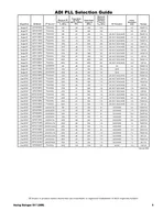
Shegaon AM Receivers Details of Each Block We have seen that AM receiver consist of blocks like 1 RF SectionAmplifier 2 MixerConverter Section 3 Local Oscillator 4 IF sectionIntermediate Frequency Amplifier ID: 1034532

mixer frequency conversion output frequency mixer output conversion input signal nonlinear amplifier section loss converter difference voltage gain circuit

Share:

Link:

Embed:

Download Presentation from below link

Download Presentation The PPT/PDF document "AM receivers K.M.Thanvi SSGMCE" is the property of its rightful owner. Permission is granted to download and print the materials on this web site for personal, non-commercial use only, and to display it on your personal computer provided you do not modify the materials and that you retain all copyright notices contained in the materials. By downloading content from our website, you accept the terms of this agreement.


Presentation Transcript

1. AM receiversK.M.ThanviSSGMCE Shegaon

2. AM Receivers: Details of Each Block

3. We have seen that AM receiver consist of blocks like:1. RF Section/Amplifier2. Mixer/Converter Section 3. Local Oscillator4. IF section/Intermediate Frequency Amplifier5. Detector Section/Amplitude Demodulator Circuits/Diode detector6. Audio Amplifier Section

4. RF SectionIt is the first stage encountered by Received signalFollowing are its desirable characteristicsLow thermal noiseLow noise figureModerate to high gainLow inter-modulation and harmonic distortionModerate selectivityHigh image frequency rejection ratio

5. Typical bipolar RF amplifier

6. Typical FET RF amplifier

7. The Purpose of Mixer/Converter stage is to down-convert the incoming RF to IFThis is accomplished by mixing the RF signals with the LO frequency in a nonlinear device. In essence, this is heterodyningA mixer is nonlinear amplifier similar to a modulator, except that the output is tuned to the difference between the RF and LO frequenciesAlthough any nonlinear device can be used for a mixer, a transistor or FET is generally preferred over a simple diode because it is also capable of amplificationMixer or Frequency Converter

8. Mixer or Frequency ConverterConversion Loss or Conversion Gain: The actual output signal from a mixer is a cross-product frequency, there is a net loss to the signalThis loss is called Conversion Loss or sometimes Conversion Gain because frequency conversion has occurred and, at the same time, the IF output signal is lower in amplitude than the RF input signalThe conversion loss is generally 6dB (conversion gain-6dB)

9. The mixer is a nonlinear device having two sets of input terminals and one set of output terminalsThe signal from the preceding RF amplifier is fed to one set of input terminals & the output of the LO is fed to the other setSuch a nonlinear circuit will have several frequencies present in its output including the difference between the two input frequenciesThe difference frequency is the IF & is the one to which the output circuit of the mixer is tunedMixer or Frequency Converter

10. Mixer or Frequency ConverterInput to mixer is input signal voltage, which has magnitude of Vs at a frequency fsThe output is usually a current component at the IF(fo-fs), whose magnitude is proportional to VsA constant of proportionality is conversion transconductanceMixing occurs when the transconductance of the mixer circuit is caused to vary with the LO voltage

11. Mixer or Frequency ConverterConversion transconductanceMagnitude of output currentMagnitude of the input signal voltage

12. Types Self excitedSeparately excited

13. Self-Excited

14. Separately-Excited