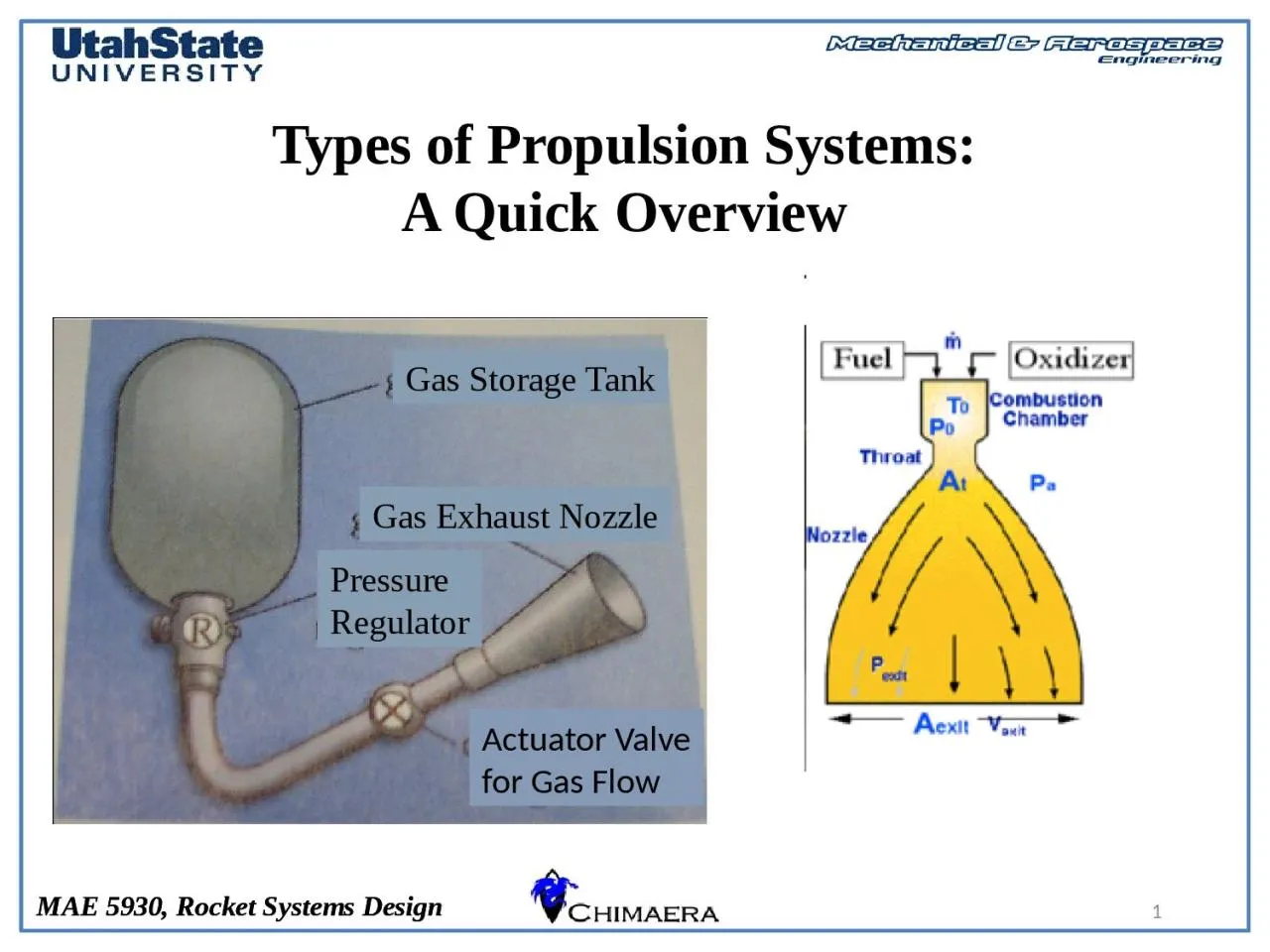
/
1 Types of Propulsion Systems: 1 Types of Propulsion Systems:

1 Types of Propulsion Systems: - PowerPoint Presentation

sylvia
sylvia . @sylvia
Follow
342 views
Uploaded On 2022-06-07

1 Types of Propulsion Systems: - PPT Presentation

A Quick Overview Actuator Valve for Gas Flow Pressure Regulator Gas Storage Tank Gas Exhaust Nozzle 2 Review Thrust Equation Thrust Oxidizer enters combustion Chamber at 0 velocity combustion ID: 914280

aerospike nozzle spike thrust nozzle aerospike thrust spike impulse gas specific truncation propellant rocket pressure mass design systems solid

Share:

Link:

Embed:

Download Presentation from below link

Download Presentation The PPT/PDF document "1 Types of Propulsion Systems:" is the property of its rightful owner. Permission is granted to download and print the materials on this web site for personal, non-commercial use only, and to display it on your personal computer provided you do not modify the materials and that you retain all copyright notices contained in the materials. By downloading content from our website, you accept the terms of this agreement.


Presentation Transcript

Slide1

1

Types of Propulsion Systems:A Quick Overview

Actuator Valve

for Gas Flow

PressureRegulator

Gas Storage Tank

Gas Exhaust Nozzle

Slide2

2

Review: Thrust Equation

• Thrust + Oxidizer enters combustion

Chamber at ~0 velocity, combustion

Adds energy … High Chamber pressureAccelerates flow through NozzleResultant pressure forces produce thrust

Slide3

3

Maximum Available Thrust

Slide4

4

Review: Specific Impulse

• Specific Impulse rocket’s Ability to deliver a certain (specific)

impulse for a given weight of propellant

Mean specific impulse

• At a constant altitude, with

Constant mass flow through engine

• Instantaneous specific impulse

Slide5

5

Review: Rocket Equation

• Sometimes

Is also called

propellant mass

Fraction or “load mass fraction”

Slide6

6

Specific Impulse (Revisited)

Slide7

7

5 Types of Chemical ThrustersCold GasMonopropellant

BipropellantSolidHybrid

Slide8

8

Cold Gas Thrusters

The balloon model: A big tank of gas, a valve, and a nozzle.

Used on early satellites for simplicityIsp of 50 seconds

thrust less than a pound

Slide9

9

Cold Gas Thrusters

• No Combustion

• Thrust provided by

expansion of gas through Nozzle• Low Isp

• Simple Mechanism

Actuator Valvefor Gas Flow

Pressure

Regulator

Gas Storage Tank

Gas Exhaust Nozzle

Slide10

10

Monopropellant systems

• Often used for

spacecraft RCS system

Slide11

11

Monopropellant systems

• Often used for

spacecraft RCS system

Slide12

12

Monopropellant Thrusters

An unstable chemical that will decompose exothermically in the presence of a catalyst.The chemical needs to be unstable, but not too unstable.V2 used hydrogen peroxide, but it decomposes in storage, leading to overpressures and water.

Current systems use Hydrazine, which decomposes into Hydrogen, nitrogen, and ammonia in the presence of iridium. Isp is on the order of 230, and total thrust can reach hundreds of lbs.

Slide13

13

Typical Solid and Liquid Rockets

Slide14

14

Bi-propellant System

Bi-prop offers the most performance (I

sp

as high as 450 sec) and the most versatility. They also offer the most failure modes and the highest price tags.

Almost all first stage liquid rockets are Bi-prop.

Slide15

15

Bi-Prop plumbing

Turbine Fed

Pressure

Fed

Slide16

16

Solid Rocket Motors

Slide17

17

Solid Rocket Motors

The oxidizer and fuel are stored in the combustion chamber as a mechanical mixture in solid formTwo conditions for use:The total Impulse is known accurately in advanceRestart is not required

Elements include: Case, Igniter, Grain, Nozzle, liner/insulationBlack PowderComposite Propellant: organic binders, aluminum powder, and an oxidizer (usually ammonium perchlorate - NH4CIO

4.) The binders are rubberlike polymers that are both fuel and binder.

Slide18

18

Burning Patterns

Slide19

19

Thrust Profiles

Slide20

20

SHAPE OF PROPELLANT GRAINS QUENCHED AT DIFFERENT TIMES

Start condition Quenched at 1.5 s Quenched at 2.5 s

Slide21

21

The “Bates Grain” Geometry

Simple Modification to Cylindrical Port to Give More

Even Burn Pattern

Grain segments burn from

“inside” and along the “ends”

Most NAR-certified solid-grain motors use this pattern

Slide22

22

Hybrid Motors

• Relatively Low I

sp

, Capable of High Thrust• Throttleable

, Restartable

, Limited explosion potential

Very difficult to precisely regulate delivered impulse for

pressure fed systems

Slide23

23

Space Dev® Hybrid Powered“Spaceship 1” (cont’d)

• Built by Burt Rutan (Scaled Composites®) with Paul Allen’s (Apple co founder)

Money in Mojave CA SS1 wrote history, when the first private suborbital

spaceflight was conducted on June 21, 2004 (with pilot Mike Melvill).

• SS1 won the X-Prize with flights on 29.09.2004 (Melville)

and a follow up flight on 04.10.2004. (Brian Binneie)• Powered by a 16700 lbf thrust Hybrid Motor (SpaceDev)

Slide24

24

System Weight Comparison

Slide25

25

Propellant Comparisons

Slide26

26

The Optimum Nozzle

Slide27

27

Operating Pressure

Slide28

28

Effect of Operating Pressure on Conventional Nozzle Performance

Credit: Aerospace web

Slide29

29

The "Optimum Nozzle”

Slide30

30

Slide31

31

"The Linear Aerospike Rocket Engine"

… Which leads us to

the … real alternative

The Aerospike Rocket Nozzle

Slide32

32

Slide33

33

Linear Aerospike Rocket Engine Nozzle has same effect as telescope nozzle

Slide34

34

Advantages of Aerospike Nozzle

Truncated

aerospike nozzles can be as short as 25% the length of a conventional bell nozzle.

Provide savings in packing volume and weight for space vehicles.Aerospike nozzles allow higher expansion ratio than conventional nozzle for a given space vehicle base area.

Increase vacuum thrust and specific impulse.For

in-space operations, advanced nozzles can increase the thrust and specific impulse by 5-6%, resulting in a 8-9% decrease in propellant mass.Lower total vehicle mass and provide extra margin for the mass inclusion of other critical vehicle systems.

New nozzle technology also applicable to RCS, space tugs, etc…

Comparison of F-1 Engine (Apollo Saturn V) to Proposed J 2T-250K

Replacement

Aerospike

Engine

Slide35

35

Performance Comparison

• Although less than Ideal

The significant Isp recovery of Spike Nozzles offer significant advantage

Annular “Plug” aerospike

Slide36

Annular Aerospike Design

36

Slide37

Ideal Aerospike Design

37

Slide38

Ideal Aerospike Design (2)

38

Slide39

Off Design Operation (1)

39

Slide40

Off Design Operation (2)

40

Slide41

Off Design Operation (1)

41

Slide42

Spikes That Have Actually Flown

42

Slide43

Effects of Spike Truncation

43

Truncation allows for

VERY SHORT LENGTH FOR A GIVEN EXPANSION RATIO

Slide44

Effects of Spike Truncation (2)

44

Slide45

Effects of Spike Truncation (3)

45

Truncation DOES NOT PRESENT A GREAT PENALTY

Slide46

Effects of Spike Truncation (4)

46

Slide47

47

Spike Nozzle … Other advantages

• Thrust vectoring without Gimbals

Credit: Aerospace web

Slide48

Spike on the “Javelin”

48

Aerospike

for Cold-gasaugmentation thruster

is a “Natural Fit” for theJavelin

Spike integrates ontoAft eng of the vehicle Wraps around attach ring of main motor nozzle

Thruster plenums may be sectors or possibly aFull annulus

Slide49

Spike on the “Javelin”

49

~92% Spike Truncation

Slide50

50

Questions??