/
International Journal of International Journal of

International Journal of - PDF document

tatyana-admore
tatyana-admore . @tatyana-admore
Follow
409 views
Uploaded On 2015-07-26

International Journal of - PPT Presentation

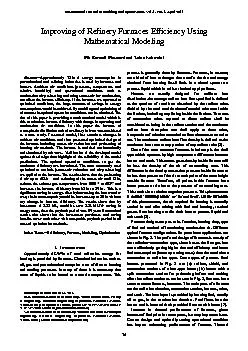
Modeling and Optimization Vol 1 No 1 April 201 1 74 Abstract x2014 Approximately 75 of energy consumption in petrochemical and refining industries is used by furnaces and heaters Ambi ID: 93541

furnace air heat excess air furnace excess heat temperature efficiency gas energy stack furnaces convection area fuel ambient design thermal combustion burning

Share:

Link:

Embed:

Download Presentation from below link

Download Pdf The PPT/PDF document "International Journal of" is the property of its rightful owner. Permission is granted to download and print the materials on this web site for personal, non-commercial use only, and to display it on your personal computer provided you do not modify the materials and that you retain all copyright notices contained in the materials. By downloading content from our website, you accept the terms of this agreement.


Presentation Transcript

International Journal of Modeling and Optimization , Vol. 1 , No. 1 , April 201 1 74 Abstract — Approximately 75% of energy consumption in petrochemical and refining industries is used by furnaces and heaters. Ambient air condit ions (pressure, temperature and relative humidity) and operational conditions such as combustion air preheating and using excess air for combustion, can affect the furnace efficiency. If the furnaces are operated at optimized conditions, the huge amounts o f savings in energy consumptions would be achieved. By modeling and optimizing of a furnace the optimal operation conditions can be obtained. The aim of this paper is providing a mathematical model which is able to calculate furnace efficiency with change in operating and combustion air conditions. In this paper the furnace of atmospheric distillation unit of a refinery in Iran was considered as a case study. Presented model, first examines changes in ambient air conditions and then presented optimized desi gn of the furnace including excess air reduction and preheating of burning air methods. The furnace is modeled mathematically and simulated by software . Verification of the developed model again st the design data highlighted the reliability of the model p redictions . The optimal operation conditions to get the maximum efficiency are introduced. The most commonly used optimization methods (excess air reduction and air preheating) are applied to the furnace. The results shows that the preheating of air up to 485.6 and reducing of the excess air until 15%, reduces the exhaust gas temperature from 1000 to 402 and increases the furnace efficiency from 63% to 89% . This is a significant saving in energy . Also by increasing t he heat transfer area, the furnace capacity could be increases up to 30% without any change in furnace efficiency. The results show that by investment of 5.23 M$, could be earn 5.81 M$/Yr saving in energy costs, then the payback period was 0.9 year. Econom ical results also show that the investment purchases and saving benefits cover each other with acceptable payback period in all cases of optimization methods. Index Terms — Eefficiency, Furnace, Modeling, Optimization I. I NTRODUCTION Approximately 65 - 90% of total refineries energy for heating is provided by furnaces. Chemical industries such as oil, gas and petrochemical comprise a set of diverse heating and cooling processes in many of them it is necessary that some of liquids to be heated to a certain tempe rature. This Manuscript received March 15, 2011. M. E. Masoumi, Islamic Azad University, Tehran North Branch, Faculty of Engineering, Chemical Engineering Department, P.O.Box:19585/936, Tehran, IRAN (correspondence author, phone: +98 21 88 77 07 42; fax: +98 21 88 78 72 04; e - mail: m_masoumi@iau - tnb.ac.ir) Z. Izakmehri, Islamic Azad Univers ity, Tehran North Branch, Faculty of Engineering, Chemical Engineering Department, P.O.Box:19585/936, Tehran, IRAN (e - mail: izakmehri510@yahoo.com) process is generally done by furnaces . Furnaces, in essence, are a k ind of heat exchanger that transfer the thermal energy obtained from burning fossil fuels in a closed space to a process liquid which in coils or locked up pipe flows. Heater s are usually designed for uniform heat distribution .the average radiant heat flux specified is defined as the quotient of total heat absorbed by the radiant tubes divided by the total outside circumferential tube area inside the firebox, including any fi tting inside the firebox. The rows of convection tubes exposed to direct radiant shall be considered as being in the radiant section and the maximum radiant heat absorption rate shall apply to these tubes, irrespective of whether extended surface elements are used or not. The maximum radiant heat flux density is defined as the maximum heart rate to any portion of any radiant tube [1]. One of the most common furnaces in industry is the draft type which operates by high temperature diff erence between burner and stack. This means gases density inside furnace will be less th e density of the air of surrounding area. This difference in the density causes that pressure inside furnace to be less than pressure of the air at each point of the same height outside furn ace. Therefore, all points inside furnace have lower pressure relative to the pressure of surrounding area . This results in a relative negative pressure . This phenomenon is termed „chimney effect‟ or „natural draft‟. Under influence of this phenomenon, the air required for burning is naturally sucked in and after mixing with fuel and burning, resulted gasses from burning transfer their heat to process liquid and exit stack [ 2 ]. Furnace designs vary as to its function, heating duty, type of fuel and method o f introducing combustion air. Different typical furnace configurations for petroleum applications are shown in Fig. 1. The preferred design of furnaces is mostly of the radiation – convection type, since it uses the flue gas heat more effectively getting hig her thermal efficiency and lower fuel consumption (lower operating costs) than the stand alone convection or radiation types . Some types of process fired heaters presented in Fig. 1 are: (a) radiant, shield, and convection sections of a box - type heater; (b ) heater with a split convection section for preheating before and soaking after the radiant section as can be seen in Fig. 1, furnaces have some common features, however. The main parts of a furnace are the radiation chamber, convection section, burners, tubes, and stack. The heat input is provided by burning fuel, usually oil or gas, in the combustion chamber. Fuel flows into the burner and is burnt with air provided from an air blower [3]. Increase in thermal performance of furnaces, given increase of fu el price in recent years, is a very important issue. Correct design and optimally setting operational condition has impact enhancing performance of furnace. Thermal Improving of Refinery Furnaces Efficiency Using Mathematical Modeling Mir Esmaeil Masoumi and Zahra Izakmehri International Journal of Modeling and Optimization , Vol. 1 , No. 1 , April 201 1 75 efficiency usually is defined as ratio of absorbed heat to total incoming energy [ 4 ]. Fi g. 1. Different box furnace configurations. Galitsky & Worrel by controlling variables such as percentage of excess air and amount of oxygen in outgoing gasses showed and assessed importance of performance increase of used energy in furnaces and its rela tion to decrease of operational cost and amount of pollution. By these methods, up to 18% saving in furnace energy consumption could be achieved [5]. Jegla, using optimization of stack temperature and air heating system, registered a new method for fur nace operation. This method is based on process integration using pinch technology and is for saving in energy consumption. This paper shows that using of gasses exiting stack energies for heating the air by a little change in operational parameters, could reduces annual energy costs of a refinery up to 20% [ 6 ]. Also in recent years, jegla presented a method for design of furnaces burner which was based on models developed by Lobo - Evans, Bloken and by defining a target function based on minimizing annual co sts of furnace, presented its optimum design [ 7 ]. There are different methods for increasing a draft type furnace performance . The most common and effective ways are : 1) Reduction of thermal wasting in walls using insulation 2) Improvement of temperature conditi on in burner 3) Improvement in energy recycling in transport sector 4) Reduction of unburned carbon on internal and external surface of the furnaces. 5) Installation of pre - heater 6) Control of excess air Amongst the above mentioned methods, pre - heating of air is norm ally applied possible for large furnaces and method of excess air control is one of the most common methods which are recommended for furnaces with low thermal performance . However its effectiveness is and de pended on operational condition s and c an be stud ied [8]. Burning proce ss requires a certain amount of air that for its accurate calculation, fuel combination should be determined . If in burning process of hydrocarbons there is not enough oxygen available, compounds like carbon monoxide are created whic h have undesirable effects on bio - environment . Therefore for obtaining full burning and ensuring polluting substances are not formed, a percentage of excess air is normally considered for the combustion process. Despite the fact that use of excess air, pr events production of compounds like carbon monoxide, but in practice, its amount can not be more than an optimum level. Since any excess air which does not react with air will escape from the exits stack, the more its amount is, the more thermal energy is wasted . Hence as a prin ciple for design and operation of furnaces the amount of excess air is regulated in an optimal condition which prevents b oth incomplete burning of the fuel and thermal energy losses. T wo main parameters used in examining a furnace pe rformance are temperature of exiting gasses from stack and amount of excess air (or oxygen ) , in stack gasses . As a rule of thumb, reduction of excess air of stack gasses to the amount of 10% or reduction of temperature stack gasses for 20 ºC by pre - heater o f the air, will cause 1% increase in furnace performance. In order to enhance furnace or boiler‟s efficiency and improvement of its functioning condition, the first and most effective action is regulation of excess air. At the moment, in most furnaces and boilers, amount of excess oxygen and draft of stack gasses are measured which are proportional to excess air. Desirable amount of excess oxygen in furnaces and boilers gas fuel shown by analyzer in exiting gasses is 3% and suitable amount of draft is about - 0.3 [ 9 ]. If there is no sufficient air for burning of fuel, then diffusion of unburned hydrocarbons and monoxide will increase. However a high level of excessive air in combustion process will produce NOx Fig.2 shows amount of diffusion of C O and N O wit h excess air in burning stoichiometric methane with the air in ambient temperature. Increasing the excess air, the amount of C O decreases but that of NO X decreases sharply before declining . Therefore it is crucial to have an optimum amount of excess air in the combustion process in order to control both CO and NO X . Burning efficiency depends on ratio of fuel to the air. In practice, use of 2 to 3% excess oxygen (about 15% excess air) indicates most suitable performance [ 10 ]. Fig. 2. Emission s of pollution for stoichiometric burning of methane with air In this paper, an optimal mathematical model for designing of industrial furnaces is developed. The presented model first examines changes in ambient air conditions such as temperature, pressur e, and relative humidity and then design the furnace using best optimize methods including reduction of excess air and pre - heating of burning air. The International Journal of Modeling and Optimization , Vol. 1 , No. 1 , April 201 1 76 aim of this paper is to provide a mathematical model which is able to calculate furnace performance at v arious conditions, and then optimize it. In addition, study of economic costs is amongst goals of this research. II. F URNACE M ODELING The combustion equation of hydrocarbon in air can be represented as in Eq. (1) . a C X H Y + b O 2 +c N 2 +d H 2 O→e CO 2 +f H 2 O+ g O 2 +c N 2 (1) Using mass balance the percent of O 2, on a dry volume basis can obtained by Eq. (2). Ambient air temperature, pressure, and humidity affect the air flow rate [9]. If the air temperature increases, the air flow rate decreases . As definite temperature, pressure and humidity of air increases, water vapor in ambient air is decreases and result to decrease the percent of O 2 . So the air flow rate through the burner at definite pressure drop by using corresponding - states defines as Eq. (3) [ 11,12 ]. The absorbed heat in convection and radiation section of furnace by crude oil can be represented by Eq. (4). Q A = Q Rad + Q con = (H out - H in) = M oil C p (T out – T in ) (4) Furnac e thermal efficiency is defined as the percent ratio of the total heat absorbed in a furnace to the net heat - released. Then considering radiant heat loss and heat losses by hot flue gases discharged through the stack, the net heat released represented as E q. (5). (5) The gas heat content entering the stack ( depends on gas temperature at that point (T S ) and excess air (x) used in the gas combustion according to a given functionality. The heat loss (Q 1 ) is considered in the range fr om 1% to 3% of the net - heat release (Q f ). From Eq. (4) and (5), the fired box efficiency ( , which depends on gas temperature at stack inlet and excess air, is computed according to the following equation [3] : The heat absorbed in radiati on chamber according to lobo - Evans method is defined as Eq. (8) [1 3 ]. The absorptive ( depends on tube spacing (C) and the outer diameters of tubes (D 0 ) and defined by Eq. (9) . The emissivity (P F ) can be c orrelated as a function of the gas average temperature and PL factor like Eq. (10) . Partial pressure of CO 2 and H 2 O ( PL ), is a function of carbon – hydrogen ratio of the fuel and percentage of excess air can be defined as Eq. (11). where: Mean Beam Length is defined in terms of the ratios of length, height and in terms of diameter and height [1 4 ]. (13) The exchange factor (F) is a function of gas emissivit y (P F ) and the ratio of refractory area (A R ) to the equivalent cold plane area ( The wall area in terms of length (L), center - to - center spacing (C), and number of tubes per row (N) is defined as: The furnace desig n requires the computation of the heat transfer areas in each furnace section. In particular, the heat transfer area for the convection section (A Con ) is computed as follows: Where LM refer to the log mean base temperature difference which is defined as follows: Heat transfer coefficient could estimate from trial term: The wall effect usually ranges in magnitude between 6% and 15% of the sum of the pure convection and radiation coefficients [13]. (19) The gas radiation coefficient is defined as: Where: Refractory walls radiation coefficient is defined as: where: The convection gas film coefficien t is defined as: (24) where: III. C ASE S TUDY For verification of the proposed model with literature, the distillation unit furnace of a refinery in Iran was considered as a case study. The operational data and furnace par ameters are listed in table 1. All data needed for furnace design calculations was not accessible, so for calculating that present in Eq. (8) until Eq. (23) Petrosim simulating software was used. Also by using from Eviews software, furnace pro cess data was fitted and constant parameters in mentioned Eq's was International Journal of Modeling and Optimization , Vol. 1 , No. 1 , April 201 1 77 calculated and presented in table 2 . A computer program was prepared using MATLAB software for designing the furnace and calculating the parameters . It has also been used for computing econ omical aspects of the furnace. A comparison between basic designed and calculated parameters of studied furnace by prepared software was achieved and presented in table 3. The results show that the modeling results and design data are very consistent (Tab le 2). This indicates that the developed model was reliable and it could be used for studying the effect of ambient conditions on furnace design ambient temperature and relative humidity at atmospheric pressure on oxygen demand of furnace. As can be seen b y increasing the ambient air temperature, the oxygen demand of furnace is reduced . Fig. 4 shows the effect of excess air and stack flue gas temperature on heat lost from furnace. As can be seen by increasing the excess air, the heat loses from furnace is i ncreased. TABLE1 : T HE PARAMETERS OF STU DIED REFINERY FURNAC E Furnace type: box type Fuel combinations Co (0.25%), N 2 (4.95%) H 2 (23.79%), H 4 (23.5%), C 2 H 6 (23.61%),C 3 H 6 (2.92%) C 3 H 8 (6.53%), C 2 H 4 (7.471%) Ambient temperature ( ) 41 - 113 Relat ive humidity 70 - 75% Firebox temperature ( ) 1550 - 1650 Fuel temperature ( ) 60 TABLE2 : T HE CONSTANT PARAMETE RS OF DIFFERENT E SQ .‟ S WHICH WAS CALCULATED BY SOFTWARE FOR THE STU DIED CASE Eq. C 1 C 2 C 3 C 4 C 5 6 3.12 E - 5 1.3 0.51 --- - ---- 9 0.0016 - 0.0907 1.1554 ---- ---- 10 - 9.517 E - 9 0.32 - 0.091 0.008 - 0.341 12 0.0007 - 0.02 0.278 ---- ---- 14 - 0.0156 - 1.2698 0.069 1.88 0.0703 20 - 0.0086 31.2 - 35.21 6.7 E - 6 ---- 22 8.91 E - 16 0.0025 - 7.55 E - 14 - 0.83 ---- 24 1.389 E - 8 4.286 E - 6 0.011 - 0.143 ---- TABLE3 : C OMPARISON OF BASIC D ESIGN AND CALCULATED PARAMETERS OF STUDIED FURNACE parameters model design T g ( 1700 1660 T W ( ) 734.6 798 T air 485.6 509 Q rad (Mbtu/hr) 168.47 18 0.13 Q conv (Mbtu/hr) 59.3 60.04 A con (ft 2 ) 18779 18579 Eq. (7) shows that the thermal efficiency percent ( ) for a gas is a function of stack gas temperature (T s ) and excess air percent (x), so the thermal efficiency could be calculated usi ng this equations. Fig. 5 presents the results of this calculation. IV. O PTIMIZATION For furnace optimization and increasing of efficiency, reduction of excess air, air preheating and increasing of heat transfer area was considered in this work and compared w ith each other fr o m economical point of view. Also presented results compared with design and in the case evaluated by energy saving. This studied furnace used 100% of excess air in operational condition, have 1000 stack temperature and 63% t hermal efficiency. Fig. 3. %O 2 vs. ambient air temperature as a function of relative humidity Fig. 4. %Heat loss vs. %O 2 as a function of stack flue gas temperature Fig. 5. Results of the proposed Eq. (7) to calculate efficiency as function of stac k gas temperature and excess air. The studies shows that by repairing heater wall and adjust damper the excess air and stack flue gas temperature could be reduced by 40% and 800 respectively. Then the furnace efficiency increases up to 76%. I f the investment expenses of heater wall maintenance and damper adjustment control system are calculated and compared with saving due to increased furnace efficiency, the payback period was calculated 0.76 year which was acceptable from economical point of view. The preheating of combustion air is the relevant method for more reducing on excess air, stack exit flue gas temperature and increasing furnace efficiency. So if a preheater set in the incoming combustion air line, by using energy balance calcu lations and dew point restrictions, preheated air temperature calculated 485.6 In result, exit flue gas of stack temperature reduced to 402 and excess air consumptions will reduce to 15%. Also the furnace efficiency International Journal of Modeling and Optimization , Vol. 1 , No. 1 , April 201 1 78 increase up to 89%. If the capital investment expenses of air preheater apparatus are calculated and compared with saving due to increased furnace efficiency, the payback period was calculated 1 year which was acceptable from economical point of view. The details of results in different cases are summarized in table 4. Case 1 refere to the existing furnace, case 2 refere to reducing of excess air strategy and case 3 for combustion air preheating plus reducing of excess air. As can be seen the results of case 3 are mor e economic than case 2. Also in case 3 furnace is operated at normal design conditions. In the revamping project where the increasing of the process throughput are considered, the main goal of the furnace optimization is the incresing of the furnace capaci ty without any changing in efficiency of the furnace. So the studies of this work show that the increasing of the furnace capacity up to 30% without any compromising in furnace efficiency are possible . Increasing of the furnace capacity requires more heat transfer area in furnace. If the investment expenses of added area are calculated and compared with saving due to increased furnace capacity, the payback period was calculated 0.9 year which was acceptable from economical point of view. The details of resu lts are summarized as case 4 in table 4. TABLE 4: O PTIMIZATION RESULTS OF STUDIED FURNACE I N DIFFERENT STRATEGIES Parameter Case 1 Case 2 Case 3 Case 4 Excees air % 100% 40% 15% 15% T g ( 1000 800 402 402 Efficiency ( ) 63% 7 6% 89% 89% 0.9964 0.9964 0.9964 0.9964 A rad (ft 2 ) 6535.4 6535.4 6535.4 9219.6 P F 0.1795 0.3559 0.38 0.37 F 0.3643 0.5139 0.5304 0.4 Q rad (Mbtu/hr) 63.5 89.67 92.5 95.7 Q F (Mbtu/hr) 203.63 231.3 228.9 297.6 h cc (btu/ft 2 . .hr) 4.47 4.255 4.11 4.11 h cr (btu/ft 2 . .hr) 2.42 2.0522 1.73 1.73 h cw (btu/ft 2 . .hr) 9.95 9.95 9.95 9.95 U (btu/ft 2 . .hr) 7.2328 6.6393 6.183 6.183 LM ( 709.267 562.7 436.08 436.08 A Con (ft 2 ) 10993 15094 20920 23889 E. saving (Mbtu/hr) 3.52 3.94 4.401 5.81 Payback time (yr) - 0.76 1.06 0.9 V. C ONCLUSIONS In this paper different method of energy saving in the refinery furnaces was evaluated. The results show that the control of excess air has significant effect on inc reasing furnace efficiency but did not adequate in furnace energy saving projects. So to increase the efficiency, combustion air preheating in line with beside of excess air reduction should be considered. Also by optimizing the furnace conditions, incresi ng of furnace capacity without changing of furnace efficiency would be possible in refinery proposed optimizing strategies are promising . Nomenclatures: A w = Area of walls in convection (ft 2 ) A t = Area of tubes in convection (ft 2 ) A con = Convection heat transfer area (ft 2 ) A CP = Cold plane area (ft 2 ) A R = Refractory area (ft 2 ) A b = Area of burner throat (ft 2 ) a= Volume fraction of hydrocarbon in the ambient air - fuel mixture b= Volume fraction of o 2 in the ambient air - fuel mixture c= Volum e fraction of N 2 in the ambient air - fuel mixture c 1 , c 2 , c 3 = Constant of coefficient C= Distance betwe en tube centers (ft) d=Volume fraction of H 2 O in the product mixture e= Volume fraction of CO 2 i n the product mixture f= Volume fraction of o 2 in the product mixture F= Correction factor G= Mass velocity at minimum cross - section (Btu/ft 2 .hr) h cr = Gas - radiation coefficient (Btu/ft 2 .hr) h cc = Convection gas film coefficient (Btu/ft 2 .hr) h r = Total apparent gas film coefficient (Btu/ft 2 .hr) H= Height of fir ebox (ft) k b = Pressure loss coefficient through burner LM= logarithm means temperture difference from flue gas to fluid ( MLB= Mean beam leng th (ft) M Oil = Oil mass fow - rate (MBtu/hr) m o air = Mass flow rate (Ib/hr) N= Total number of radiant ∆ p b = Airside pressure drop across burner (psig) P F = Gas emissivity Q con = Heat transfer rate absorbed in the convection section (Mbtu/hr) Q A = Heat absorbed by the oil (Mbtu/hr) Q rad = Heat transfer rate absorbed in the radiant section (Mbtu/hr) Q gs = Heat content of gas leaving the convection section (Mbtu/hr) Q n = Net heat - released from the fuel combustion (Mbtu/hr) T cw = Average tube wall temperature (convection section) ( T gc = Avarage gas temperature(co nvection section) ( T i = Inlet temperature of oil T c = Cross - over oil tempreture T g = Exit gas tempreture T s = Inlet stack tempreture T w = Average tube wall ( U= Over - all transfer cof ficient (btu/ft 2 .hr) W= Wide of firebox (ft) Greek symbols = Absorptivity of a tube surface = Stefan bolltzman constant = Fired heater efficiency Subscripts : ATAP= Actual temperature and actual pressure C X H Y = Hydroca rbon R EFRENCES : [1] Alireza bahadori, Hari B.Vuthaluru. "Novel predictive tools for design of radiant and convection sections of direct fired heaters", Applied Energy, Vol. 87, pp.2194 - 2202,2009. International Journal of Modeling and Optimization , Vol. 1 , No. 1 , April 201 1 79 [2] Francis Wildy, "Fired Heater Optimization", AMETEK Process In struments, 2000. [3] S. Mussati, Juan I."Manassaldi,Mixed Integer Non Linear Programming Model For The Optimal Design Of Fired Heaters",Applied Thermal Engineering, Vol. 29, pp.2194 - 2204, 2009. [4] Hassan Al - Haj Ibrahim."Thermal efficiency of fired heater," 2008. [5] Worrell E,Galitsky C. Energy efficiency improvement and cost saving opportunities for petroleum refineries , Lawrence Berkeley National Laboratory report LBNL - 56183. Berkeley, CA [6] Z Jegla, P. Stehlik, J. Kohoutek, "Plant energy saving through efficient r etrofit of furnaces", Applied Thermal Engineering Vol.20, pp. 1545 - 1560, 2000. [7] Z Jegla "The Conceptual Design of a Radiant Chamber and Preliminary Optimization of a Process Tubular Furnace ", Heat Transfer Engineering, Vol.27, pp.50 - 57, 2006. [8] Jegla,Z., Koh outek, J., And Stehlik, P.," Global Algorithm For Systematic Retrofit Of Tubular Process Furnaces", Applied Thermal Engineering, Vol. 23, pp.1797 - 1805, 2003 [9] Taal, M., Bulatov, I., Klemes, J. And Stehlik, P., "Cost Estimation And Energy Price Forecasts For Economic Evaluation Of Retrofit Projects,Applied Thermal Engineering", Vol.23, pp. 1819 - 1835, 2003. [10] A.Garg.”Revamp fired heater rating “.hydrocarbon processing, pp.67 - 80, 1998. [11] Bussman W, Baukal C. "Ambient condition effects on process heater emissions", Energy, 2008. [12] W.R. Bussman,C.E. Baukal,"Ambient condition effects on process heater efficiency", John Zink Co. LLC, 11920 East Apache, Tulsa, Energy,2009. [13] W.E. Lobo, J.E. Evans, "Heat transfer in the radiant section of petroleum heaters",Trans AIChE , 743 – 778. 1939 [14] Nelson, W.L. "Petroleeum Refinery Engineering", 4th ed, Mc Graw - Hill.