/
T-DAR Four-Head Mantrap Installation Check List Newton Security Inc. - T-DAR Four-Head Mantrap Installation Check List Newton Security Inc. -

T-DAR Four-Head Mantrap Installation Check List Newton Security Inc. - - PDF document

tatyana-admore
tatyana-admore . @tatyana-admore
Follow
434 views
Uploaded On 2015-08-31

T-DAR Four-Head Mantrap Installation Check List Newton Security Inc. - - PPT Presentation

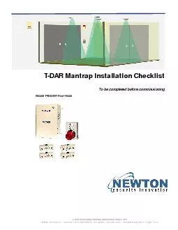
U er Front Panel Connections TDAR Control Box Front Panel Connections TDAR FourHead Mantrap Installation Check List Newton Security Inc 443 SW 41st Street Renton WA 98055 2062519494 Revis ID: 119124

U er Front Panel Connections T-DAR Control

Share:

Link:

Embed:

Download Presentation from below link

Download Pdf The PPT/PDF document "T-DAR Four-Head Mantrap Installation Che..." is the property of its rightful owner. Permission is granted to download and print the materials on this web site for personal, non-commercial use only, and to display it on your personal computer provided you do not modify the materials and that you retain all copyright notices contained in the materials. By downloading content from our website, you accept the terms of this agreement.


Presentation Transcript

T-DAR Four-Head Mantrap Installation Check List Newton Security Inc. - 443 SW 41st Street Renton, WA 98055 - 206-251-9494 - Revised 6 May 2011 - Page 2 of 4     U er Front Panel Connections T-DAR Control Box Front Panel Connections T-DAR Four-Head Mantrap Installation Check List Newton Security Inc. - 443 SW 41st Street Renton, WA 98055 - 206-251-9494 - Revised 6 May 2011 - Page 4 of 4 For steps #11 through #20, link a PC to the T-DAR control unit using an Ethernet connection. Once established, connect to the control box using the T-DAR User Interface (UI) application. The status the bottom of the user interface. Connect a video monitor or VGA monitor to the video or VGA out ports of the T-DAR control unit. the “Monitor” tab of the UI to set the video output. There is a drop-down menu in the “Display Demo” section, indicating Portal 1, Portal 2, Portal 3, and Portal 4. Select Portal 1 from the dropdown menu and observe two separate images on the lower half of the video monitor. Verify that these images are motionless, clear, and not shifted up or down. For Portal 2 through 4 in the dropdown menu, verify that the images are motionless, clear, and that they are not shifted up or downSelect “Show I/O” on the “Monitor” tab of the user interface. For the public door contact. Test and verify that as the public door closes, Input #4 changes from red to green on the input/output display of the monitor. If the public side is a double-door unit, then Input #4 should only show green when both doors are closed. For the Secure Door Public Valid. Test and verify that as the Secure Door Public Valid Access is granted (access grant signal from inside mantrap) Input #6 changes from red to green on the input/output display of the monitor. Test and verify that as the secure door closes, Input #6 changes from red to green on the input/output display of the monitor. If the secure side is a double-door unit, then Input #6 should only show green when both doors are closed. Test and verify that as the Secure Door Secure Valid request is granted (signal from outside mantrap, on the secure side), Input #3 changes from red to green on the input/output display of the monitorIf a door encoder is installed, as required on inward-swinging public doors, be sure that Inputs #7 and #8 oscillate red and green on the input/output display of the monitor, during door movement. If the public side is a double-door unit, Inputs #13 and #14 should also oscillate red and green on the monitor’s input/output display, during door movement. For Supervisor Override. Test and verify that as the Supervisor Override indicator activates (when override button is pressed), Input #1 changes from red to green on the monitor input/output display.Verify that both the public and secure door locks engage immediately when the T-DAR unit sends locking signals to either of these doors. If there is a delay in lock engagement on the public door lock, after a T-DAR lock command, the door will be able to be pushed open during the interlock process. This is also true for the secure door if there is a delay in its locking process. Verify that an alarm output line extends to the building security center and that this line is connected across Relay #5 (pins C8 and C9). For public doors with their own access readers, ensure that the T-DAR as well as the access control system can both lock the public door, in parallel (independently). The public door will lock when the T-DAR and/or the access control system locks it. Also, ensure that no readers providing access to the public door (inside or out) interface directly with T-DAR. If the lighting above the doorway is provided by low frequency florescent fixtures operating at 60Hz or less, verify that a low-voltage, AC transformer has been installed and connected to the Line Lock and Ground terminals (A9 and A10) in the T-DAR control box. The Line Lock transformer voltage should be 6-30VAC. checklist______________________________________________________________________