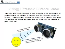
/
Highly Doped Silicon Substrate(opposite type of doping) Highly Doped Silicon Substrate(opposite type of doping)

Highly Doped Silicon Substrate(opposite type of doping) - PDF document

tawny-fly
tawny-fly . @tawny-fly
Follow
461 views
Uploaded On 2016-03-04

Highly Doped Silicon Substrate(opposite type of doping) - PPT Presentation

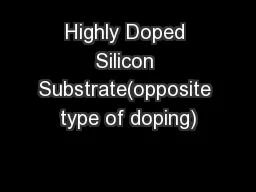
Top ViewCross section Hg probe Implant SiO2 Highly Doped Silicon Substrateopposite type of doping Top ViewCross section Hg probe Implant SiO2 Fig 3 Schematic drawing of the test structure used ID: 241041

Top View:Cross section: Hg probe Implant SiO2 Highly Doped

Share:

Link:

Embed:

Download Presentation from below link

Download Pdf The PPT/PDF document "Highly Doped Silicon Substrate(opposite ..." is the property of its rightful owner. Permission is granted to download and print the materials on this web site for personal, non-commercial use only, and to display it on your personal computer provided you do not modify the materials and that you retain all copyright notices contained in the materials. By downloading content from our website, you accept the terms of this agreement.


Presentation Transcript

Highly Doped Silicon Substrate(opposite type of doping) Top View:Cross section: Hg probe Implant SiO2 Highly Doped Silicon Substrate(opposite type of doping) Top View:Cross section: Hg probe Implant SiO2 Fig. 3. Schematic drawing of the test structure used for measuring of the leakage current of USJ layers. SUGGESTED WAY OF DETERMINING DRAIN-SOURCE PUNCH THROUGH VOLTAGE Since the main reason of monitoring USJ junction depth is for detecting whether the USJ is shallow enough for avoiding drain to source distance being too close that punch through can happen at a too low voltage, one actually can directly measure the punch through voltage if simple layout for emulating drain-source structure can be made for such measuring. To do this, one can design a mask for opening oxide windows for implantation on wafer so that four specially made mercury probes can be used to contact one to two pairs of adjacent windows as shown in Fig.4. Each two adjacent windows are separated by several drain-source channels in parallel. If I-V curve is measured between these two windows, punch through voltage can be easily identified. Each of the above mentioned window is called drain-source connection window. Fig.4 shows a design for enabling the proposed punch through voltage test. Drain-source connection windows, in rectangular shape of 1.8 mm x 1.5 mm, can be lined up in stripes. Separating any two adjacent drain-source connection windows in a stripe is a parallel array of drain-source channels in real size. Applying a voltage between two adjacent drain-source connection windows can cause a current to flow through these channels. Whenever the punch through voltage is reached, a sudden increase of the current signals it’s happening. Four specially arranged mercury probes of 0.8 mm in diameter each with center-to-center distance of 1.2 mm can be used for making contacts to drain-source connection windows. Each pair of the probe in the same row is shorted together for making probing not so easily missing these windows for testing. Implant windows (Drain-source connection windows) GateLine Gate Width,Palled array of several drain-source channels A Hg Probe Contacts,D=0.6mm Two probes short externally; apply voltage and measure current between the two couples of Hg probe. The distances between the probes and the windows are set so that each I-V measurement is only across one or two gate line. 1.5 mm 1.5 mm1.8 mm 1.2 mm 1 mm sq1.5mm 2 mm drainsource Implant windows (Drain-source connection windows) GateLine Gate Width,Palled array of several drain-source channels A Hg Probe Contacts,D=0.6mm Two probes short externally; apply voltage and measure current between the two couples of Hg probe. The distances between the probes and the windows are set so that each I-V measurement is only across one or two gate line. 1.5 mm 1.5 mm1.8 mm 1.2 mm 1 mm sq1.5mm 2 mm drainsource Fig. 4. Illustration of how to use of Hg mercury probes for drain-source punch through voltage check. CONCLUSION As the doping density of the background increases toward 10 18 cm -3 , four-point probe’s measurement repeatability deteriorates quickly, even if the probe tips are conditioned to be very smooth and flat. In this case, mercury four-point probe, with its smoothest flattest, and most elastic tips possible, is shown theoretically and experimentally, providing the best repeatability. Therefore it is proposed to use mercury four-point probe measurements as the reference for other USJ layer sheet resistivity measurements techniques. We also suggest to use repeatability of mercury four-point probe measurements to such highly doped USJ layer for checking whether the layers defect density is too high. USJ layer’s leakage can be measured and mapped using an automatic single-dot mercury probe to contact the USJ in drain and source windows. Instead of constantly monitoring USJ junction depth, determining the punch though voltage through specially prepared punch through test patterns is more direct and accurate for the purpose and may be more practical in production environment. REFERENCES 1. R.J. Hillard, et. al., Solid State Technology, 47, Aug., 2004. 2. J. T.C. Chen, Private communication with VSEA. 3. S. Wolf, “Semiconductors”, Wiley, pp.55-56, 1971. 4. S.M. Sze, “Physics of Semiconductor Devices”, 2 nd Ed., John Wiley & Sons, p.16 & p.265, 1981.