/
International Journal of Scientific and Resea rch Publications  Volume  Issue   June International Journal of Scientific and Resea rch Publications  Volume  Issue   June

International Journal of Scientific and Resea rch Publications Volume Issue June - PDF document

tawny-fly
tawny-fly . @tawny-fly
Follow
592 views
Uploaded On 2014-12-12

International Journal of Scientific and Resea rch Publications Volume Issue June - PPT Presentation

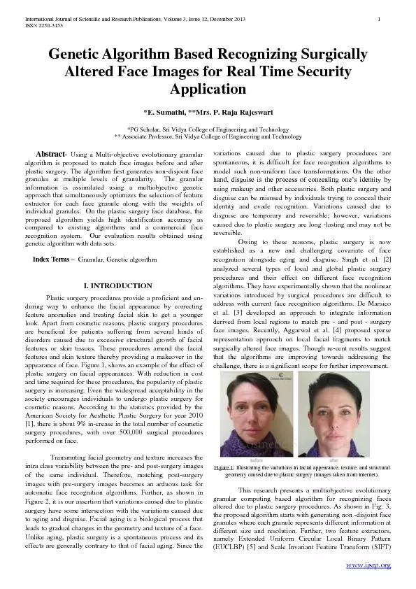
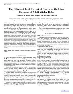
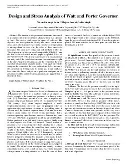
ijsrporg Design and Stress Analysis of Watt and Porter Governor Ravindra Singh Rana Rajesh Purohit Alok Singh Assistant Professor Department of M echanical Engineering MANIT Bhopal MP India Associate Professor Department of M echanical Engineering M ID: 22774

ijsrporg Design and Stress Analysis

Share:

Link:

Embed:

Download Presentation from below link

Download Pdf The PPT/PDF document "International Journal of Scientific and ..." is the property of its rightful owner. Permission is granted to download and print the materials on this web site for personal, non-commercial use only, and to display it on your personal computer provided you do not modify the materials and that you retain all copyright notices contained in the materials. By downloading content from our website, you accept the terms of this agreement.


Presentation Transcript

International Journal of Scientific and Resea rch Publications , Volume 2, Issue 6 , June 2012 1 ISSN 2250 - 3153 www.ijsrp.org Design and Stress Analysis of Watt and Porter Governor *Ravindra Singh Rana, **Rajesh Purohit, *Alok Singh *Assistant Professor Department of M echanical Engineering M.A.N.I.T, Bhopal (M.P.) , India **Associate Professor Department of M echanical Engineering M.A.N.I.T, Bhopal (M.P.) , India Abstract - The function of the governor is to maintain the speed of an engine within specified limits whenever there is a variation of load.. This device can be used in almost all vehicles. The objective our investigat ion to identify the stress concentration areas, areas which are most susceptible to failure when governor is rotating about its axis, also the value of these stresses is measured. This a nalysis is carried out with the help of PRO E. The displacement of the various elements of the SPINDLE from the base is also calculated and the graphs are plotted. Effect of the “WEIGHT OF THE ARMS” is the major area of concern for our study and all the calculations are done considering the weight of the arms. Weight of the arms acts on the centroid of the arms and when the governor assembly rotates, centrifugal force starts acting on the centroid of the arms and tends to deflect the arms, this deflection or bending is to be minimized. In our work, we have done the Stress ana lysis on a particular configuration of governor assembly and then various materials are suggested on a theoretical basis. Index Terms - PRO E, Spindle, Weight of the Arms. I. I NTRODUCTION Governor, or speed limiter, is a device used to measure and reg ulate the speed of a machine, such as an engine. A classic example is the centrifugal governor, also known as the watt. [1 - 3] Centrifugal governors were used to regulate the distance and pressure between millstones in windmills since the 17th century. Earl y steam engines employed a purely reciprocating motion, and were used for pumping water an application that could tolerate variations in the working speed. It was not until the Scottish engineer James Watt introduced the rotative steam engine, for driving factory machinery, that a constant operating speed became necessary. Between the years 1775 and 1800, Watt, in partnership with industrialist Matthew Bolton, produced some 500 rotati - vebeam engines. At the heart of these engines was Watts self - designed "co nical pendulum" governor: a set of revolving steel balls attached to a vertical spindle by link arms, where the controlling force consists of the weight of the balls. Building on Watts design was American engineer Willard Gibbs who in 1872 theoretically an alyzed Watts’s conical pendulum governor from a mathematical energy balance perspective. During his graduate school years at Yale University, Gibbs observed that the operation of the device in practice was beset with the disadvantages of sluggishness and a tendency to overcorrect for the changes in speed it was supposed to control. The objective our investigation to identify the stress concentration areas, areas which are most susceptible to failure when governor is rotating about its axis, also the value o f these stresses is measured. Analysis is carried out with the help of PRO E. The displacement of the various elements of the SPINDLE from the base is also calculated using PRO E and the graphs are plotted. Different materials for different parts are used that are theoretically justified. II. MATERIALS FOR DIFFERENT PARTS 2.1 Spindle and Arms: The spindle of the governor is made of STAINLESS STEEL. The properties of stainless steel are given below: Physical Properties, Density= 0.29 lbs/in3(8.03 g/cm3) ,M odulus of Elasticity ksi (MPa) 28.0 x 10³ (193 x 10^3) in tension 11.2 x 10³ (78 x 10^3) in torsion. STAINLESS STEEL is used because of its high MODULUS OF ELASTICITY in tension and the high modulus of elasticity in tension means high bending strength, whi ch is the major cause for failure of the spindle, it is for this reason that stainless steel is used for the design of spindle. Apart from that the Corrosion resistant property of stainless steel and its stress concentration corrosion resistance justify th e use of stainless steel for both spindle and arms. 2.2 Base: The base of the governor assembly is made up of Fe30. This material is used because it has very good Vibrations Damping capacity. It is a prerequisite for the governor or any machine that the base should be stable and it should not vibrate, it is for this reason that Fe30 is used. 2.3 Sleeve and Head: The sleeve of the governor is made up of BRONZE. Sleeve is that part of governor which moves relatives to spindle so there is always FRI CTION associated with it, and when there is friction, then when the sleeve is moving upwards friction acts downwards and retards its speed and when it moves downwards friction acts upwards, in this way for a given height of governor there are two speeds on the controlling curve which results in the INSTABILITY of the governor. The friction of the governor is therefore be kept as low as possible, Bronze is a material which is self - lubrication and it has very low coefficient of friction. 2.4 Pins and Bu shes: Self - lubricating bushings (lubrication free bushings) are made up of one of two basic compositions:  PTFE - Based Metal - Polymer Materials  Thermoplastic - Based Metal - Polymer Materials III. D ESIGN OF G OVERNOR 3.1 Design of Watt Governor: The Design of Watt Gove rnor involves determining the Minimum and maximum speed of the Governor. The minimum speed occurs when the sleeve is at its rest or initial position. A International Journal of Scientific and Resea rch Publications , Volume 2, Issue 6 , June 2012 2 ISSN 2250 - 3153 www.ijsrp.org . Here, AB - length of the arm (cm),BC = r = Radius of rotation (cm ) ,AC =h = Height of the Governor (cm) 30° = α = Angle of inclination Length AB =41cm; BC= 146mm; α= 30º Height of governor, WKT hı = AB * cosα = 14.6 * cos30º= 12.64 cm or .126 m But hı= 895/Nı² , Nı²= 895/.126 Minimum speed, Nı=84.2 rpm. ,Assume sleeve lift =20mm h2 = hı – 20 mm= 106.4 mm or .1064 mMax speed N2² = 895/h2�= 895/ .335N2= 91.46 rpm Speed range % = (N1 ≈ N2)/ N2= (91.77 – 84.22) / 84.22= 8.37 % DESIGN OF SHAFT: Diameter of the shaft„d ‟ = 13 mm, For d20 mm; τ=σy / 2 where σy is the yield stress (N/mm^2) ,σy = 380 N/mm^2. From DDB.�= τ= 190 N /mm², where τ is the shear stress in N/mm^2 W.K.T.T=п /16 *τd³ , Where T - torque in the shaft „Nmm ‟ =п /16 * 190* 13³= 81962.18 Nmm => 81.962 Nm Power = 2пNT/60, Max speed N= 91.77 rpm= 2*п*91.77* 81.962 / 60=454.94 W The power obtained is less than that of the power rating of a FHP motor which is 746 W and hence the design is safe for 13 mm diameter of shaft. 3.2 Design of Porter Governor: The porter governor is a modificatio n of a watts governor; with central load attached to the sleeve. This leads to larger centrifugal forces here high speeds are required to bring the fly balls to the same radius. The design of porter governor involves determining the minimum and maximum spe ed of the governor. The minimum speed occurs when the sleeve is at its rest or initial position. The only difference between the watt and porter governor is the inclusion of a dead weight as shown in the figure. International Journal of Scientific and Resea rch Publications , Volume 2, Issue 6 , June 2012 3 ISSN 2250 - 3153 www.ijsrp.org Basic Sp ecifications: (1) Power supply (2) 230 V AC, Single phase, Variance. Materials :( 1) Spindle: Stainless Steel (2) Fly balls: Cast Iron (3) Arms: Stainless steel(4) Frame: Mild steel(5) Dead weight: cast Iron Governor Mechanism: Speed of rotation, N= (m+ M)/m * 895/h,Where m is Mass of the ball (kg) M – Mass of the dead weight (kg)h – Height of the governor (cm) ,r – Radius of rotation (cm),α – Angle of inclination,Fc – Centrifugal force = m ώ^2 r., Where ώ= 2 π N/ 60. N - Speed of rotation (rpm), Here m= .4 kg M= 1.6 kgi) Height of Governor: h =√ (AB² - BC²), Here the Length of the arms is equal, Radius of rotation, r ı = AB sin α= .146 * sin 30º= .534 m Hı = AB cosα = 12.64 cm Speed N² = (m + M)/m * 895 / h1= (.4 + 1.4)/.4*895/ .1246N =179.21 rpm DESIGN OF SHAFT: For solid shaft d= 13 mm, τ=σy/ 2 where τ is the shear stress in N/mm² ,σy = 380 N/mm^2. From DDB. τ= 380/ 2 = 190 N/mm² Torque ,T =п / 16 *τd³=п / 16 * 190 * 13³=81.962 Nmiv) Power = 2пNT/60= 2п*179.21*81.962/60 = 723.26 WP < [P] i.e. The power obtained is less than that of the power r ating of a FHP motor which is 746 W and hence the design is safe for 13 mm diameter of shaft. Hence design is safe Specifications of Bearing: A Bearing is a machine element which is mounted on shafts for free and smooth rotation. The bearing facili tates the rotation of the shaft along its axis without any vibration. Generally for this purpose roller ball bearing is chosen and we have done the same. The various stresses acting on a roller ball bearing are ( i) Radial force acting on the bearing.(ii) A xial thrust on the bearing The design of bearings is done on the basis of the stresses induced, the size of the setup and its specifications (i )The figure shows the dimensions of the bearing chosen. A roller ball bearing of ID 26 mm and OD 52mm (ii)The ID is chosen as 26mm so as to fix the sleeve rigidly on the bearing. Design Procedure : (i)The design of bearings is done on the basis of the stresses induced and the size of the setup. (ii) The radial force acting on the govern or is given by F = torque / distance. (N)F = 81.951 / .30Radial force F = 275 N (iii) For F = 275 N and the inner diameter d = 26 mm, The bearing to be chosen is SKF 6006. SKF 6206 and SKF 6306. Out of which SKF6206 is highly recommended and chosen by us. Additional Bearing : Two more bearings are required for free flow movement of the spindle connected to the motor with the help of a pulley. The bearing of inner diameter13 mm is required so that the Shaft is rigidly supported by the frame. Design : The Rad ial Force acting on the Governor is given by F = torque / distance. (N)=81.962/ 36Radial Force F = 216.75 N. For F = 216.75 N and the inner diameter d = 12 mm, The Bearing to be chosen is SKF 6006. SKF 6206 and SKF 6306. Out of which SKF 6206 is highly rec ommended and chosen by us. Hurdles Faced: International Journal of Scientific and Resea rch Publications , Volume 2, Issue 6 , June 2012 4 ISSN 2250 - 3153 www.ijsrp.org (i)We experienced bending the spindle while trying to fix the bearing in position which later led to wobbling of the spindle. Hence we changed a new one later. (ii) Due to irregular sp eed control the arms bent while rotating which we replaced later with a new arm of harder material to overcome that problem. (iii) We also experienced turbulence of the entire setup while operating due to less weight of frame for which we added some extr a weight for stability. (iv)Fixing the bearing in position caused failure of bearings because of hard impact by hammer for which we replaced the faulty bearing later. IV. R ESULTS AND D ISCUSSION (1.) From the stress analysis of the various parts of the g overnor assembly we are able to identify the stress concentration areas, which are most susceptible to fail, so to avoid failure we have to increase the strength in those areas and to achieve this diameter of the shaft should be increased near the base bec ause this is the portion where stress concentration is highest, so we have to provide a step a to increase the area which is accompanied by fillet which has some radius to avoid stress concentration. (2.) As can be seen from the stress analysis the ar ea near the joint of the arm and the spindle head has high stress concentration so the thickness of the arms should be a SPLINE with high thickness near the joint and low at the centre, spline design is chosen because we do not have to increase the weight of the arms. Displacement of the Spindle STRESSES on various elements Strain at v arious elements of the assembly International Journal of Scientific and Resea rch Publications , Volume 2, Issue 6 , June 2012 5 ISSN 2250 - 3153 www.ijsrp.org Stress Curve with respect to spindle head semi perimeter Strain energy curve wrt spindle head Displacement Magnitude w.r.t. spindle head Limitations of our Study: (i) Bending of the spindle, because of the for ces acting on the spindle head by the arms. (ii) High sensitivity which results in HUNTING. (iii) Woobling of the whole structure because of low weight. V. FUTURE SCOPE (i) Analysis on different materials for spindles and arms. (ii) Dynamic analysis of the governor will give more accurate results and also calculate the combined stresses acting on the various parts of the governor. (iii) Application of springs to avoid the problem of HUNTING. (iv) The governors extend their scope in all kind of vehicles. They can be employed in hydro plants assessment. (v)They can also be used in speed sensing devices which employ digital speed governors. (vi) The introduction of analog and digital speed governors have created a rage among the automobile industries VI. CONC LUSION (i) Thus governor plays an important role in speed control. (ii) It ensures regulation of speed at any conditions (iii)To study the effect of varying the mass of the center sleeve in porter governor R EFERENCES [1] WWW.ANSWERS.COM /TOPIC/GOVER - DE [2 ] WWW.ENOTES.COM/TOP IC/GOVER - DE [3] HTTP//EN.WIKIPED IA.ORG/WIKI/GOVER - DE International Journal of Scientific and Resea rch Publications , Volume 2, Issue 6 , June 2012 6 ISSN 2250 - 3153 www.ijsrp.org A UTHORS First Author – Ravindra Singh Rana , Assistant Professor Department of Mechanical Engineering M.A.N.I.T.Bhopal(M.P.), Email: ravindrarana74@gmanil.com Second Author – Rajesh P urohit , Associate Professor Department of Mechanical Engineering M.A.N.I.T.Bhopal(M.P.) Third Author – Alok Singh , Assistant Professor Department of Mechanical Engineering M.A.N.I.T.Bhopal(M.P.)