/
Making Our Own High-Quality SMA Test Cables Making Our Own High-Quality SMA Test Cables

Making Our Own High-Quality SMA Test Cables - PowerPoint Presentation

tawny-fly
tawny-fly . @tawny-fly
Follow
432 views
Uploaded On 2015-09-30

Making Our Own High-Quality SMA Test Cables - PPT Presentation

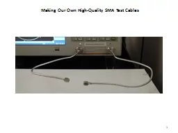
1 2 Always use a gage kit after making a cable to ensure the pin and the dielectric of the SMA connector are in spec Maury Microwave A027A gage kit Belden 1673A 0141 od conformal cable ID: 145126

cables cable connector test cable cables test connector sma phase conductor dielectric calibration male pin heat solder set you

Share:

Link:

Embed:

Download Presentation from below link

Download Presentation The PPT/PDF document "Making Our Own High-Quality SMA Test Cab..." is the property of its rightful owner. Permission is granted to download and print the materials on this web site for personal, non-commercial use only, and to display it on your personal computer provided you do not modify the materials and that you retain all copyright notices contained in the materials. By downloading content from our website, you accept the terms of this agreement.


Presentation Transcript

Slide1

Making Our Own High-Quality SMA Test Cables

1Slide2

2

Always use a gage kit after making a cable to ensure the pin and the dielectric of the SMA connector are in spec.

Maury Microwave #A027A gage kit

Belden #1673A 0.141” o.d. conformal cable

AmphenolRF #901-9808 captivated contact SMA connectorsSlide3

Making Our Own High-Quality SMA Test Cables

Materials (pricing as of October 2013)AmphenolRF #901-9808 captivated contact SMA connectors Mouser.com $6.07 ea @qty 25Belden #1673A 0.141” o.d. Conformable cable Tallycom.com $4.24/foot

Tools

Heat-sink adapter (custom copies of the SanTron assembly adapter #1209-03-P)

Maury Microwave #A027A SMA gage kit

We’ll use the heat-sink adapter (the secret sauce!) to prevent the dielectric from ooshing out during the step of

soldering the outer braid (don’t apply more heat than needed). These heat-sink adapters are in the tools case on the GSI desk in the lab.

After assembly, always use the Maury Microwave #A027A gage kit to ensure the pin depth and dielectric depth are in spec.Always inspect under a stereo microscope.

Don’t allow any out-of-spec cables to remain in the lab. Out-of-spec cables can crush the fingers in the connectors on the ECal!3

Note: AmphenolRF is different than Amphenol Connex. Look on

www.amphenolrf.com for the #901-9808. Slide4

4

The Reasons to Make Our Own High Quality Test Cables:

To ensure the ECal, an $11,000 instrument, and/or the mechanical cal standards, do not get broken

To ensure our cables have good phase stability, so we can measure accurately

Commercially available cables of this quality cost $100s of dollars each

This is a 3.5 mm precision slotless connector (female):

We want to protect the ports on this ECal:Slide5

5

SMA connectors have the same mechanical dimensions as 3.5 mm connectors, but have a plastic dielectric between the

i

nner and outer coaxial conductors (in a 3.5 mm connector, the dielectric is air).

This is a close-up view of a male SMA plug connector that’s more or less made correctly:Slide6

6

Here are some close-up views of really bad male SMA plug connectors. These were hand-made in a Cory research lab. There’s a learning curve to crimping such cables and assemblying them correctly.

Notice how far out the shoulder of each center pin protrudes from the end face of the surrounding cylinder.

Throw these cables away. If you plug a bad cable such as either of these into an ECal or a mechanical cal standard, or attach this to the test port of a network analyzer, and then torque them tight, you’ll ruin the female port connector. The ECal’s female center receptor will get its fingers squashed and will no longer make a uniform transmission line.

That means you’ll get reflections, or worse, flaky intermittent problems that are hard to debug.

Always inspect a connector or cable under a stereo microscope to make sure it’s clean, and then gage it, before plugging it into any equipment.Slide7

7

Crushed fingers:

If your SMA cables are out of spec (the male pin protrudes in the positive direction), then if you connect your SMA cable to a female 3.5 mm ECal port or mechanical calibration standard, you can ruin the ECal or the standard, by breaking the fingers inside the center conductor which are designed to accept the male pin. ECals and mechanical calibration standards are very expensive, so always check your SMA cables (visually under a microscope and with a pin-depth gage) before plugging an ECal.

Here’s an example of how an ECal port connector has been destroyed:

3.5 mm connectors use what are called precision slotless connections for the center receptacle. There are fingers which expand, in order to accept the male pin, but they’re inside a solid cylinder which doesn’t expand. Consequently, the geometry between the inner and outer conductors stays uniform, creating a uniform transmission line through the connection.

These fingers have been broken because a male pin’s shoulder, which protruded too far, hit them. That is, when the two mating connectors were tightened, the protruding shoulder on the male connector squished the fingers down into this cylinder on the ECal’s female port connector.

The finger is folder over and smushed down in here.Slide8

8

The web page for these AmphenolRF #901-9808 captivated contact SMA male plug connectors we’ll be using to make our custom

t

est cables, is here:

www.amphenolrf.com

Then search for 901-9808:

Click on Assembly InstructionsSlide9

9

Always measure the pin depth and dielectric depth, using the gages, both before and after assembly

. First, zero the MP (male pin) and MD (male dielectric) gages with the gage master:

Then attach the male 901-9808 connector to each of the male pin and male dielectric gages to check that your connectors are within spec. You’ll want to compare these measurements to measurements after soldering to see if the connector’s pin and/or the dielectric moved due to the heating:Slide10

10

The assembly instructions for the 901-9808 say you’ll need to strip the cable 0.125” (3.2 mm):Slide11

11

The manufacturer of the RG-402 conformal cable we’ll be using is Belden

and the part number is #1673A.

One distributer is Talley: www.talleycom.com

The gage size of the solid inner conductor is AWG 19.

That is it’s 0.036” in diameter, or 36 mils.

1 mil = 0.001”

It lives here in the Cory 111 lab:Slide12

12

This is the AmphenolRF 901-9809 captivated-contact SMA connector. With a captivated-contact type of connector, when you buy the connector, the pin is already in the connector and set to the correct depth.

This is the Belden #1673A 0.141” outer diameter conformable coax cable. After stripping a longer length, use the calipers to measure 0.125” and cut the inner conductor to 0.125”.

Then file off any burrs from the end of the inner conductor.

A wire

stripper, calipers and

a file are in

plastic boxes

on the GSI’s desk. Slide13

13

Blades for cutting

Blades for stripping. There isn’t one for AWG 19, so try the slot for AWG 18 and inspect under a microscope. The slot for AWG 16 seems to not knick the inner conductor.Slide14

14

Roll your thumb on this knob to slide the head left and right

Tighten this knob to lock the head so it can’t be moved

Ruler in mm

Ruler in inches, with 0.1” (100 mil) incrementsSlide15

15

With the jaws closed, the dial should read 0.000”.

This would be 0.010” (10 mils)

53 mils

+ 1 inch = 1.053”

1 inchSlide16

16

Untighten to loosen the bezel around the dial, for resetting the white dial face to have the zero line up with the black rotating pointer, when the jaws are closed (and clean ...

w

ipe off any debris between the faces of the jaws).

Zeroing knobSlide17

17

Yes, the inner conductor does measure as 36 mils in diameter.

Now lock down the jaws at this distance with this knob.Slide18

18

Now transfer to the wire strippers and compare to the AWG 18 slot. The cable inner conductor is spec’d as being AWG 19 gage (higher numbers mean smaller diameter wire), and 36 mils is indeed a bit smaller than the AWG 18 slot. Makes sense. Slide19

19

Try stripping with the AWG 18 slot. Inspect under the microscope. If the center conductor is knicked, cut off the end and try again, using the AWG 16 slot.Slide20

20

The way this would be done at a cable assembly house is that they would use a semi-automatic cable stripping machine:

One of the research labs has such a machine.

The resulting stripped cable comes out nicely cut with a very flat, clean face.

We’ll clean up our stripped cables with a razor blade ...Slide21

21

You can find razor blades in the blue plastic box also:

Work under the stereo microscope.

Make sure to turn on the light source.

Touch up the stripped face witha razor blade.Slide22

22

Hand stripping leaves the end face ragged.

Cut it flat with the razor blade.

Use the razor blade to pick out any metal debris:Slide23

23

Slide the calipers to the length you need to strip (125 mils) and lock with the locking knob:

With the calipers locked, you’ll have a free hand to cut the stripped end to length with a diagonal cutter:Slide24

24

Next, de-burr the edge of the inner conductor, by filing the end.

De-burring the end means to simply remove any jagged edges, so that the inner conductor will slide easily into the hole in the back of the SMA connector.Slide25

25

De-burring the end of the inner conductor is important because the inner conductor must fit snuggly into the hole in the back of the SMA connector.

The inner conductor is neither soldered nor crimped to the SMA connector. It’s strictly a press-fit into this #901-9808.

After filing and removing any burrs, inspect under the stereo microscope. This cable was stripped with the semi-automatic cable stripping machine, and then the center conductor was manually filed to debur the end. When you strip with a hand stripper and then touch up the end face with a razor blade, it won’t come out quite this beautiful.

Because there is only a press fit for the inner conductor, you have to ensure that the face of the cable is flat so it will

p

ress and mate firmly against the dielectric of the connector in order to make a clean (low mis-match) connection. The length of the stripped inner conductor should also be precisely 125 mils to fit all the way into the center hole.

Want this clean and flat.Slide26

26

If you see metal debris on the end face of the insulating dielectric when inspecting under the microscope, get rid of the debris by blowing with air, and/or picking the metal pieces out with a razor blade (also in the plastic box). The goal is to make a clean squared-off interface between the cable and the connector so as to create as uniform of a transmission line as possible.

Then push the connector onto the cable. Push it all the way in.

Next, screw the heat-sink adapter into the SMA connector. It will act as a heat sink during the soldering process.Slide27

27

The heat-sink adapters also live in the blue plastic box:Slide28

28

The heat-sink adapter is actually a SanTron assembly tool, #1209-03-P. This is kept in the plastic box with the cablemaking tools on the GSI’s desk in Cory 111. Use it when making these types of cables. The pictures below show each end of the tool. Screw in the end shown on the right into the connector you’re assembling onto the conformable cable. When you solder the outer braid of the conformable cable onto the neck of the connector, the heat from the soldering iron can cause the dielectric in the SMA connector to move. This tool prevents that from happening, or tries to. Don’t apply more heat than you need to. Use flux (the other secret sauce!). If you apply excessive heat, the dielectric face depth will end up out of spec. Slide29

29

The machine shop made up some more of these heat sink adapters (Nov. 2013). They live here in the Cory 111 lab:

The red masking tape is to make them easy to spot when left on the lab benches. If you see one left on a bench, please put it back in this box.

Hold the cable in a vise and solder the neck, using the heat sink to suck the heat away from the dielectric.Slide30

30

The point of failure will always be at the solder joint at the neck, so you never want to bend the cable in such a way as to induce stress at the neck.

Solder is brittle, which is why most really high quality connectors are crimped. However, crimper tools cost $100s of dollars and can walk away, so they’re not a viable solution for the Cory 111 lab. Hence this solution for making our own high-quality test cables.

Use flux, and solder the outer braid to the connector neck. You don’t need to use huge amounts of solder, but you must solder all sides of the cable in order to get solder all the way around. Again, you’re trying to make a uniform coaxial transmission line, so you want the outer braid to make good contact circumferentially around the neck of the SMA connector.

Note: Solder is brittle! If/when this cable breaks, it will break here.Slide31

31

Uses the gages to make sure the pin depth and dielectric depth are still within spec after soldering:Slide32

32

Never allow your cables to bend at the solder joint.

Keep them straight up until some point

far from the soldered neck:

You can bend conformal cable as much as you want in any way you want, just remember to not let it bend at the neck.

Also, after you cal, you don’t want to move them too much. The calibration is for a certain configuration of your cables.Slide33

33

The general strategy in working with these cables is to first make sure the network analyzer is sitting flat on the lab bench where you want to work. Then bend the cables to fit the ECal. Make sure no stress is applied at either neck. Keep the cables straight at each neck.

After calibration, you’ll only bend the cables just enough to attach to your device under test. If you tape the cables down, your test setup should be nice and stable while you make measurements.Slide34

34

At some point during the term, you will notice a cable is broken at the neck. Don’t throw the entire cable away. Instead, fix it.

Cut off the bad connector (the top one in the picture below, the other one is fine) and throw that away. Then re-strip the cable and solder on a new connector, following the instructions just outlined.

Gage the new connector before and after soldering, and also test the phase stability when you finish.Slide35

35

Network Analyzer Quality Tests to Verify Cable PerformanceSlide36

36

Cable Stability Tests

Phase S21 test

LogMag S11 test

SWR testSlide37

37

Pre-testing: Checking Your Cables’ Phase Stability Before Starting a Calibration

Hit the Preset button. Select OK. Displays LogMag S11.

Hook up a cable between Ports 1 & S. Why does LogMag S11 look like this? Because there are always slight impedance mismatches at connections, so we see reflections and re-reflections, albeit 30 dB down.

Hit the Meas key, and choose S21. LogMag S21 looks like this (close to 0 dB) as almost all the signal from Port 1 makes its way to Port 2:Slide38

38

To test our cables, we want to look at the Phase of S21. Hit the Format key and choose phase. The sweep here is up to 4.5 GHz, so phase wraps around about 14 times at that frequency for this particular length of cable.

Hit the Display hard key. Choose:

Data->Memory

U

nder Dat Math, choose:

Data/Memory

That will make the Phase S21 trace

b

ecome zeroed: Slide39

39

Zoom in. Hit the Scale hard key. Set the scale to 1 degree/division:

Now wiggle and bend the cable. The phase changes as you bend or stretch the cable.Slide40

40

Now stop touching the cable. Wait for the trace to settle. Now the phase goes a bit negative by the time the sweep reaches 4.5 GHz. Check how far off the phase is from zero at your frequency of interest.

Once you calibrate, and start moving the cables all around, this different bit of phase each time you change calibration standards and move the cables around during a calibration procedure, is going to get incorporated into the calibration’s error-correction coefficients.

Try it again. Wiggle the cable around some more, then take your hands away and see where it settles. This time we see a bit of positive phase at the upper frequencies.

Expensive cables are usually expensive because they have

g

ood phase stability.Slide41

41

Cable Stability Tests

Phase S21 test

LogMag S11 test

SWR testSlide42

42

Dunsmore Advice on Pre-Testing Cables

(from the Agilent web forum)

“To

test the cable:

Place the cable on one port of the VNA, attach a Short

or Open standard from a calkit on the other end. Don't cal. Just

do Data->Mem and Data-Mem (that's right, Data -Minus- Memory

). Look at the result in dB. Immediately after that,

the trace should show -70 or -80 dB return loss. Now flex the cable back and forth and up and down. The trace for a "GOOD" cable should be -50

dB. If the highest spot on the trace is above -30 dB it is a "BAD" cable. Take a wire cutter and immediately cut the cable in 20. For me, I would not use a cable that is worse than -40 dB

.”Let’s do this test on a few cables in our lab...Slide43

43

Short standard

Alternatively, you can modify a female SMA jack.

Cut the center signal pin flat against the face and solder copper tape to make a low inductance short.

LogMag S11

(ref set to -50 dB,

scale set to 10 dB/division)

Phase S11

(ref set to 0 dB,

scale set to 1 deg/division)

Just after Data->Mem for each window, and Data-Mem for the top, and Data/Mem for the bottom

Now after wiggling and letting it settle.

This cable is really bad.

Cable #12Slide44

44

Short standard

LogMag S11

(ref set to -50 dB,

scale set to 10 dB/division)

Phase S11

(ref set to 0 dB,

scale set to 1 deg/division)

Just after Data->Mem for each window, and Data-Mem for the top, and Data/Mem for the bottom

Now after wiggling and letting it settle.

This cable is pretty good.

Cable #2Slide45

45

Here’s a very good cable (brand new, $50, came with a sheet showing its factory test).

Just after saving into memory, before wiggling:

After wiggling and letting it settle. Below -50 dB for all freqs up to 4.5 GHz. Good.Slide46

46

Cable Stability Tests

Phase S21 test

LogMag S11 test

SWR testSlide47

A Third Cable Test – the SWR Test

This is probably the best test. The SWR test is the way Scotts Valley Magnetics and SanTron, two high-end cable assemblers, test their cables:

Attach your cable to Port 1 of the network analyzer

Attach a 50 ohm cal standard or any 50 ohm load to the other end

A perfect cable and 50 ohm load would show an SWR of 1.00

Under the Format menu (Format hard key), select SWR

If the SWR measurement is under 1.22, SanTron says it’s a good cable (albeit they measure to 20 GHz)

47Slide48

48

Should say “SWR”.

Hit the Scale hard key. You’ll see the defaults for an SWR format are: the Reference

P

osition is set to the 0

th

division. The Reference Value is 1.00. Then set the Scale/Div to 0.1:

The yellow triangle marks the Reference Position for the yellow trace. Here, the Reference Position is at the 0

th

division.

You shouldn’t need to calibrate the network analyzer to do your cable pre-testing. The default factory setting (hitting the Preset hard key) should be a good enough calibration setting to test your cables for whether you should throw them in the garbage or not.

50 ohm cal standard

Or make your own low inductance 50 ohm load from a

Female SMA jack. Cut off the legs and solder two 100 ohm resistors in parallel:Slide49

49

Of course, if you do this test with the exact same cable, on the broken network analyzer (Network Analyzer C), you’ll get some crazy results.

Network Analyzer C’s Port 1 says that this same cable has an SWR of 3.4!

If you calibrate this network analyzer before you test the cable, you won’t get such a bad reading. However, the calibration will work so hard to “fix” the errors, that subsequent measurements will always have dynamic range degraded.Slide50

50

Cables are really bad if the male pin’s shoulder sticks out beyond the reference plane, since that can

damage cal standards or test port savers. Don’t use those.

Other cable problems can be calibrated out to some extent. That is, as long as the trace is stable, then any mismatch, phase delay and loss can be calibrated out. But if they cables aren’t stable, they’ve probably been crimped or have cracked, and consequently make intermittent connections.

When you’ve achieved a “good” calibration, it can last for a week or two because the network analyzer itself is a fairly precise instrument, but we often change our setups, so this is moot.

Re-calibration should be done if you dis-connect and re-connect cables, or if you change the frequency sweep settings such that the sweep is over a larger range than when calibration was done.

Calibration does not have to be re-done however, when simply changing the output power level of the analyzer (e.g.

for amplifier measurements). Older analyzers used to require re-calibration after a power level change, but our E5071Cs don’t need to be re-calibrated after changing the power level.Final caveat: if you’re in a room with air conditioners turning on and off, very precise measurements can sometimes detect that temperature change.

When are “bad” cables okay to use? When do you need to re-calibrate?