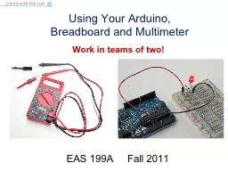
Breadboard and Multimeter EAS 199A Fall 2011 Work in teams of two Your Multimeter leads probes pincer clips good for working with breadboard wiring You will use the multimeter to understand and troubleshoot circuits mostly ID: 611596
Download Presentation The PPT/PDF document "Using Your Arduino," is the property of its rightful owner. Permission is granted to download and print the materials on this web site for personal, non-commercial use only, and to display it on your personal computer provided you do not modify the materials and that you retain all copyright notices contained in the materials. By downloading content from our website, you accept the terms of this agreement.
Slide1
Using Your Arduino, Breadboard and Multimeter
EAS 199A Fall 2011
Work in teams of two!Slide2
Your Multimeter
leads
probes
pincer clips – good for working
with
breadboard
wiring
You will use the multimeter to understand and troubleshoot circuits, mostly
measuring DC voltage, resistance and DC current.
T
urn
knob to
select the type of measurement.
(push these onto probes)Slide3
The Arduino Duemilanove
Power can be provided through the USB cable (+5V from
the computer) or externally (7-12V supply recommended)
Duemilanove
means “2009” in ItalianSlide4
The Arduino
Uno
Power can be provided through the USB cable (+5V from
the computer) or externally (7-12V supply recommended)
The Arduino Uno was released in September 2010 as an update to the
DuemilanoveSlide5
Measure V
in
Vin
is the voltage of the power supply. The
USB supplies a nominal 5V (4.43V was measured when this photo was taken)Slide6
Change power source and measure Vin
In this photo, a 7V DC power supply was plugged into the power jack of the Arduino.Slide7
Check Voltage at 5V Power Pin
The on-board voltage regulator maintains the
voltage on the 5V pin at about 5V
The measured voltage is close to
5V target.Slide8
Check Voltage at
3.3V Pin
The FIDI chip on the Arduino, which helps the microcontroller talk with your computerthrough the USB cable, also has an on-board voltage regulator that outputs 3.3V.
If you
need less than
5V for
a project,
you
can
use
the 3.3V
pin,Which provides about3.3V. The currentdraw from the 3V3 pin
is limited to 50mA. max power = V∙I
= 3.3V∙0.05A = 0.165W = 165mWSlide9
Select Resistors
Find the 330
W and the 10kW resistors from your parts kit .
Now, find the 10kW
resistor.
Example:
330
W
resistor:
3
=
orange
3
= orange
Add 1 zero to
33 to make 330, so 1 = brown
So,
330
=
orange
,
orange
,
brown
color
digit
black
0
brown
1
red
2
orange
3
yellow
4
green
5
blue
6
violet
7
gray
8
white
9
first
digit
second
digit
number
of zeros
tolerance
gold = ±5%
silver = ±20%Slide10
Check Resistance of ResistorsSlide11
Building
a circuit on a breadboardSlide12
LED circuit:
T
wo
equivalent picturesSlide13
Building an LED Circuit
Supplies
:
2 two jumper wires – colors don’t matter, but red is usually used for positive, and black is used for negativeLED
330
Ω
and 10kΩ resistors
Arduino
Breadboard
USB
cable from your computer)Slide14
LEDs
Electricity can only flow one way through an LED (or any diode).
The flat spot on the LED must be connected to ground (GND).
LED = Light Emitting Diode
Diagram from Wikipedia description of an LED
electronic symbol
+ -Slide15
Building an
always-onLED Circuit
Short
leg of LED connectsto ground wireSlide16
Breadboard LED circuitSlide17
The Circuit
These
circuit diagrams
are equivalent
Symbol
for ground (GND)Slide18
Replace the
330W
Resistor with the 10k
W Resistor
What happens and Why??
ANSWER:
The smaller resistor
(
330
Ω
)
provides less resistance to current than the larger resistor (10kW). For the same applied voltage, increasing the resistance decreases the current.
Therefore, replacing the 300Ω resistor with the 10kΩ resistor reduces the current and causes the LED to glow less brightly.
What would happen if you forgot to put in a resistor? You would probably burn up your LED.Slide19
Arduino program to blink an LEDBuild the circuit on the breadboard
A slight modification to always-on LED circuitWrite your first Arduino programUse the digital (on/off) output to turn LED on and offSlide20
Connect the Power Wire to
Pin
2
(Use P2 as a digital output)
Enter and run the following program:
void setup
() {
// initialize
pin
as an output:
pinMode(2,
OUTPUT); }void loop
() { /
/ turn the LED on
digitalWrite
(2,
HIGH
)
;
/
/ wait 1
second = 1000 ms
delay
(1000)
;
// turn the LED
off
digitalWrite
(2,
LOW
)
;
/
/ wait for 500
ms
delay
(500)
;
}Slide21
How the Program Works
HIGH = 5V and LOW = 0V
(Always!!!!)
void setup
() {
pinMode
(2,
OUTPUT
);
}
void loop
() {
digitalWrite
(2,
HIGH);
delay
(1000);
digitalWrite
(2,
LOW
);
delay
(500);
}
initialize pin
2
as an output
infinite loop
set pin
2
to LOW (0V)
wait 500 ms
set pin
2
to HIGH (5V)
wait 1000 ms
time (ms)
voltage (V)
0V
5V
500 ms
1000 msSlide22
Now Experiment on Your Own!
Try changing the time to 1.5 seconds on and 1 second off
Connect the resistor to digital pin 5 and change the program to match
Blink out SOS in Morse code (dot-dot-dot-dash-dash-dash-dot-dot-dot)three short pulses (0.25 seconds each) followed by . . .
three long pulses (0.75 second each) followed by . . .
three short pulses (0.25 seconds each) followed by . . .
a brief pause (1 second)
repeat a through d using an infinite loop
Show your instructor when you have completed exercise (3)Slide23
Find the each command in the reference section of arduino.cc
(discuss each command with others at your table)
void setup
() {
// initialize the digital pin as an output:
pinMode
(2,
OUTPUT
);
}
void loop
() { digitalWrite(2,
HIGH); // set the LED on
delay(1000); // wait for a second
digitalWrite(2,
LOW
);
// set the LED off
delay
(500);
// wait for 500 ms
}