
05 Aug 2009 Concept Design Review Aquantis C-Plane
AS
Published · 29 slides · 0 views

1 / 1

Description
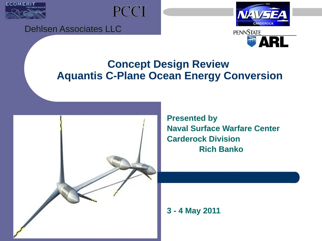
05 Aug 2009 Concept Design Review Aquantis C-Plane Ocean Energy Conversion Presented by Naval Surface Warfare Center Carderock Division Rich Banko 3 - 4 May 2011 Dehlsen Associates LLC Notional Concept Analyzed for Vertical Plane Stability
Related Topics
Share
Embed code
Download this presentation From Below
"05 Aug 2009 Concept Design Review Aquantis C-Plane" is the property of its rightful owner. Permission is granted to download and print the materials on this website for personal, non-commercial use only, and to display it on your personal computer provided you do not modify the materials and that you retain all copyright notices contained in the materials. By downloading content from our website, you accept the terms of this agreement.
Presentation Transcript
01
05 Aug 2009 Concept Design Review
Aquantis C-Plane Ocean Energy Conversion Presented by
Naval Surface Warfare Center
Carderock Division
Rich Banko
3 - 4 May 2011 Dehlsen Associates LLC<br>
Naval Surface Warfare Center
Carderock Division
Rich Banko
3 - 4 May 2011 Dehlsen Associates LLC<br>
02
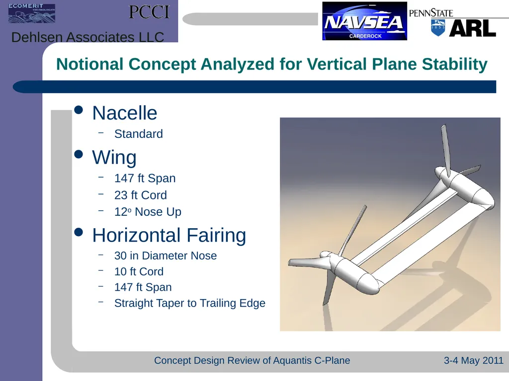
Notional Concept Analyzed for Vertical Plane Stability 3-4 May 2011 Concept Design Review of Aquantis C-Plane Dehlsen Associates LLC Nacelle
Standard
Wing
147 ft Span
23 ft Cord
12o Nose Up
Horizontal Fairing
30 in Diameter Nose
10 ft Cord
147 ft Span
Straight Taper to Trailing Edge<br>
Standard
Wing
147 ft Span
23 ft Cord
12o Nose Up
Horizontal Fairing
30 in Diameter Nose
10 ft Cord
147 ft Span
Straight Taper to Trailing Edge<br>
03
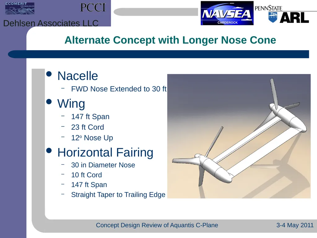
Alternate Concept with Longer Nose Cone 3-4 May 2011 Concept Design Review of Aquantis C-Plane Dehlsen Associates LLC Nacelle
FWD Nose Extended to 30 ft
Wing
147 ft Span
23 ft Cord
12o Nose Up
Horizontal Fairing
30 in Diameter Nose
10 ft Cord
147 ft Span
Straight Taper to Trailing Edge<br>
FWD Nose Extended to 30 ft
Wing
147 ft Span
23 ft Cord
12o Nose Up
Horizontal Fairing
30 in Diameter Nose
10 ft Cord
147 ft Span
Straight Taper to Trailing Edge<br>
04
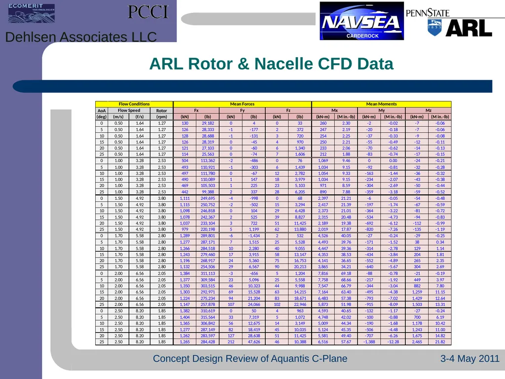
ARL Rotor & Nacelle CFD Data 3-4 May 2011 Concept Design Review of Aquantis C-Plane Dehlsen Associates LLC<br>
05
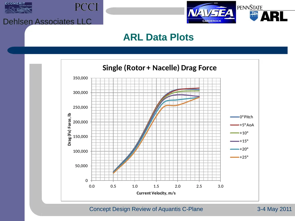
ARL Data Plots 3-4 May 2011 Concept Design Review of Aquantis C-Plane Dehlsen Associates LLC<br>
06
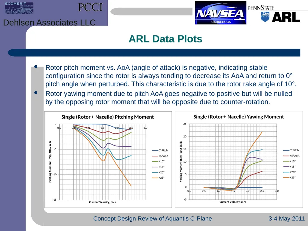
ARL Data Plots Rotor pitch moment vs. AoA (angle of attack) is negative, indicating stable configuration since the rotor is always tending to decrease its AoA and return to 0° pitch angle when perturbed. This characteristic is due to the rotor rake angle of 10°.
Rotor yawing moment due to pitch AoA goes negative to positive but will be nulled by the opposing rotor moment that will be opposite due to counter-rotation. 3-4 May 2011 Concept Design Review of Aquantis C-Plane Dehlsen Associates LLC<br>
Rotor yawing moment due to pitch AoA goes negative to positive but will be nulled by the opposing rotor moment that will be opposite due to counter-rotation. 3-4 May 2011 Concept Design Review of Aquantis C-Plane Dehlsen Associates LLC<br>
07
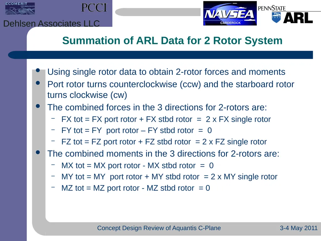
Summation of ARL Data for 2 Rotor System Using single rotor data to obtain 2-rotor forces and moments
Port rotor turns counterclockwise (ccw) and the starboard rotor turns clockwise (cw)
The combined forces in the 3 directions for 2-rotors are:
FX tot = FX port rotor + FX stbd rotor = 2 x FX single rotor
FY tot = FY port rotor – FY stbd rotor = 0
FZ tot = FZ port rotor + FZ stbd rotor = 2 x FZ single rotor
The combined moments in the 3 directions for 2-rotors are:
MX tot = MX port rotor - MX stbd rotor = 0
MY tot = MY port rotor + MY stbd rotor = 2 x MY single rotor
MZ tot = MZ port rotor - MZ stbd rotor = 0 3-4 May 2011 Concept Design Review of Aquantis C-Plane Dehlsen Associates LLC<br>
Port rotor turns counterclockwise (ccw) and the starboard rotor turns clockwise (cw)
The combined forces in the 3 directions for 2-rotors are:
FX tot = FX port rotor + FX stbd rotor = 2 x FX single rotor
FY tot = FY port rotor – FY stbd rotor = 0
FZ tot = FZ port rotor + FZ stbd rotor = 2 x FZ single rotor
The combined moments in the 3 directions for 2-rotors are:
MX tot = MX port rotor - MX stbd rotor = 0
MY tot = MY port rotor + MY stbd rotor = 2 x MY single rotor
MZ tot = MZ port rotor - MZ stbd rotor = 0 3-4 May 2011 Concept Design Review of Aquantis C-Plane Dehlsen Associates LLC<br>
08
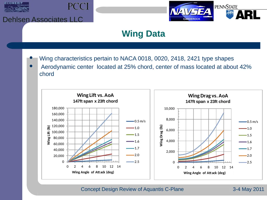
Wing Data Wing characteristics pertain to NACA 0018, 0020, 2418, 2421 type shapes
Aerodynamic center located at 25% chord, center of mass located at about 42% chord 3-4 May 2011 Concept Design Review of Aquantis C-Plane Dehlsen Associates LLC<br>
Aerodynamic center located at 25% chord, center of mass located at about 42% chord 3-4 May 2011 Concept Design Review of Aquantis C-Plane Dehlsen Associates LLC<br>
09
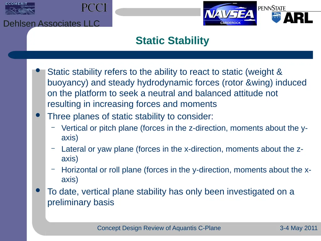
Static Stability 3-4 May 2011 Concept Design Review of Aquantis C-Plane Dehlsen Associates LLC Static stability refers to the ability to react to static (weight & buoyancy) and steady hydrodynamic forces (rotor &wing) induced on the platform to seek a neutral and balanced attitude not resulting in increasing forces and moments
Three planes of static stability to consider:
Vertical or pitch plane (forces in the z-direction, moments about the y-axis)
Lateral or yaw plane (forces in the x-direction, moments about the z-axis)
Horizontal or roll plane (forces in the y-direction, moments about the x-axis)
To date, vertical plane stability has only been investigated on a preliminary basis<br>
Three planes of static stability to consider:
Vertical or pitch plane (forces in the z-direction, moments about the y-axis)
Lateral or yaw plane (forces in the x-direction, moments about the z-axis)
Horizontal or roll plane (forces in the y-direction, moments about the x-axis)
To date, vertical plane stability has only been investigated on a preliminary basis<br>
10
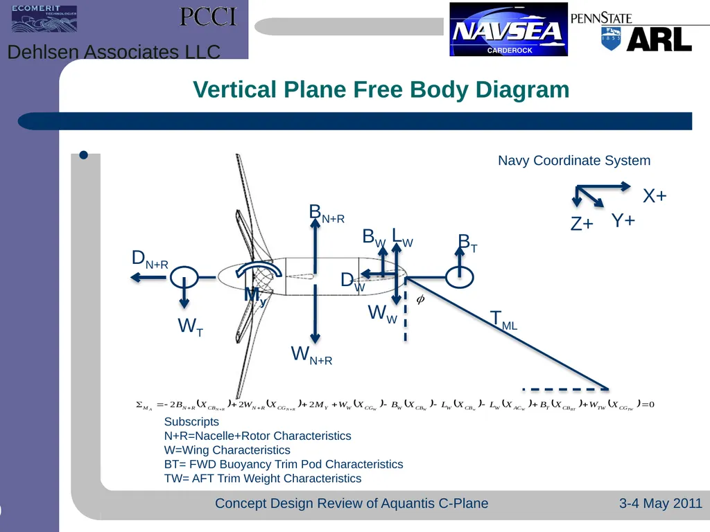
Vertical Plane Free Body Diagram 3-4 May 2011 Concept Design Review of Aquantis C-Plane Dehlsen Associates LLC Navy Coordinate System<br>
11
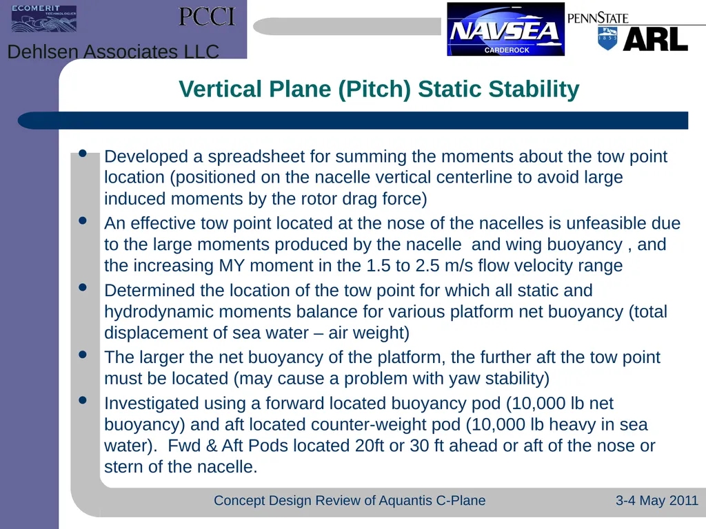
Vertical Plane (Pitch) Static Stability 3-4 May 2011 Concept Design Review of Aquantis C-Plane Dehlsen Associates LLC Developed a spreadsheet for summing the moments about the tow point location (positioned on the nacelle vertical centerline to avoid large induced moments by the rotor drag force)
An effective tow point located at the nose of the nacelles is unfeasible due to the large moments produced by the nacelle and wing buoyancy , and the increasing MY moment in the 1.5 to 2.5 m/s flow velocity range
Determined the location of the tow point for which all static and hydrodynamic moments balance for various platform net buoyancy (total displacement of sea water – air weight)
The larger the net buoyancy of the platform, the further aft the tow point must be located (may cause a problem with yaw stability)
Investigated using a forward located buoyancy pod (10,000 lb net buoyancy) and aft located counter-weight pod (10,000 lb heavy in sea water). Fwd & Aft Pods located 20ft or 30 ft ahead or aft of the nose or stern of the nacelle.<br>
An effective tow point located at the nose of the nacelles is unfeasible due to the large moments produced by the nacelle and wing buoyancy , and the increasing MY moment in the 1.5 to 2.5 m/s flow velocity range
Determined the location of the tow point for which all static and hydrodynamic moments balance for various platform net buoyancy (total displacement of sea water – air weight)
The larger the net buoyancy of the platform, the further aft the tow point must be located (may cause a problem with yaw stability)
Investigated using a forward located buoyancy pod (10,000 lb net buoyancy) and aft located counter-weight pod (10,000 lb heavy in sea water). Fwd & Aft Pods located 20ft or 30 ft ahead or aft of the nose or stern of the nacelle.<br>
12
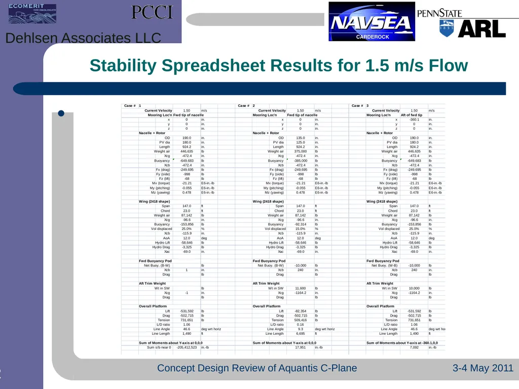
Stability Spreadsheet Results for 1.5 m/s Flow 3-4 May 2011 Concept Design Review of Aquantis C-Plane Dehlsen Associates LLC<br>
13
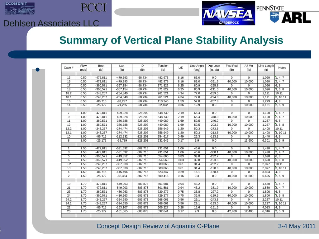
Summary of Vertical Plane Stability Analysis 3-4 May 2011 Concept Design Review of Aquantis C-Plane Dehlsen Associates LLC<br>
14
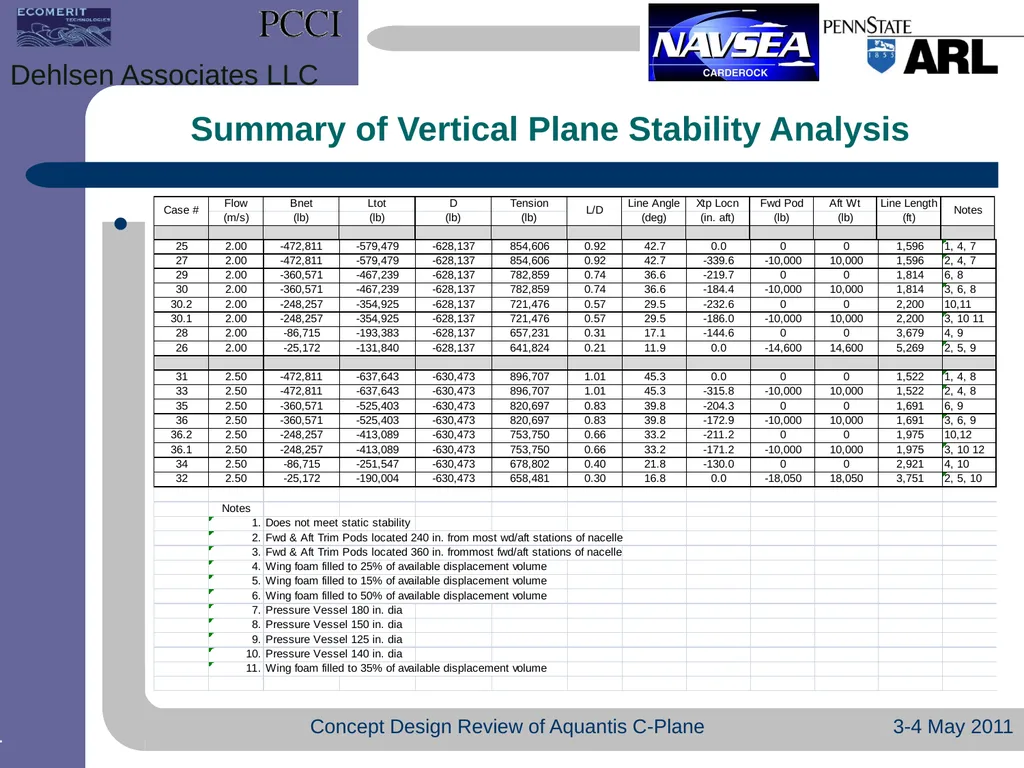
Summary of Vertical Plane Stability Analysis 3-4 May 2011 Concept Design Review of Aquantis C-Plane Dehlsen Associates LLC<br>
15
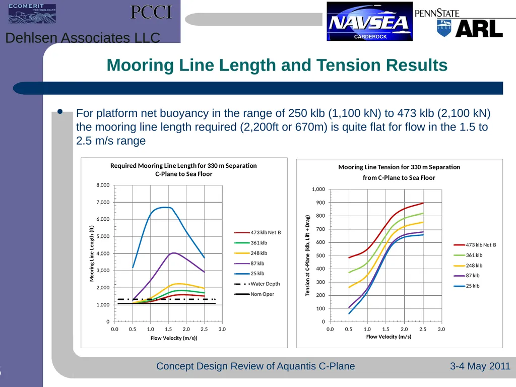
Mooring Line Length and Tension Results For platform net buoyancy in the range of 250 klb (1,100 kN) to 473 klb (2,100 kN) the mooring line length required (2,200ft or 670m) is quite flat for flow in the 1.5 to 2.5 m/s range 3-4 May 2011 Concept Design Review of Aquantis C-Plane Dehlsen Associates LLC<br>
16
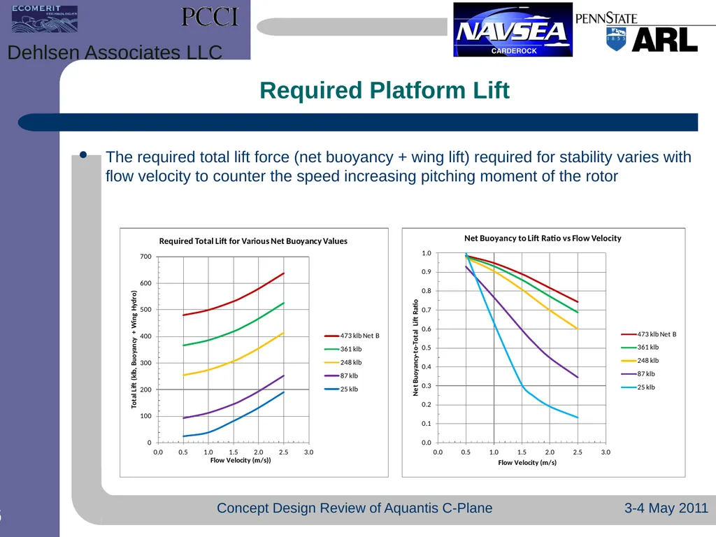
Required Platform Lift The required total lift force (net buoyancy + wing lift) required for stability varies with flow velocity to counter the speed increasing pitching moment of the rotor 3-4 May 2011 Concept Design Review of Aquantis C-Plane Dehlsen Associates LLC<br>
17
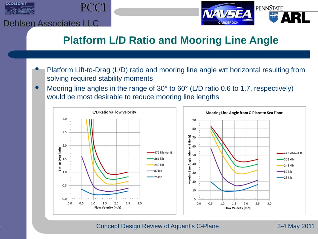
Platform L/D Ratio and Mooring Line Angle Platform Lift-to-Drag (L/D) ratio and mooring line angle wrt horizontal resulting from solving required stability moments
Mooring line angles in the range of 30° to 60° (L/D ratio 0.6 to 1.7, respectively) would be most desirable to reduce mooring line lengths 3-4 May 2011 Concept Design Review of Aquantis C-Plane Dehlsen Associates LLC<br>
Mooring line angles in the range of 30° to 60° (L/D ratio 0.6 to 1.7, respectively) would be most desirable to reduce mooring line lengths 3-4 May 2011 Concept Design Review of Aquantis C-Plane Dehlsen Associates LLC<br>
18
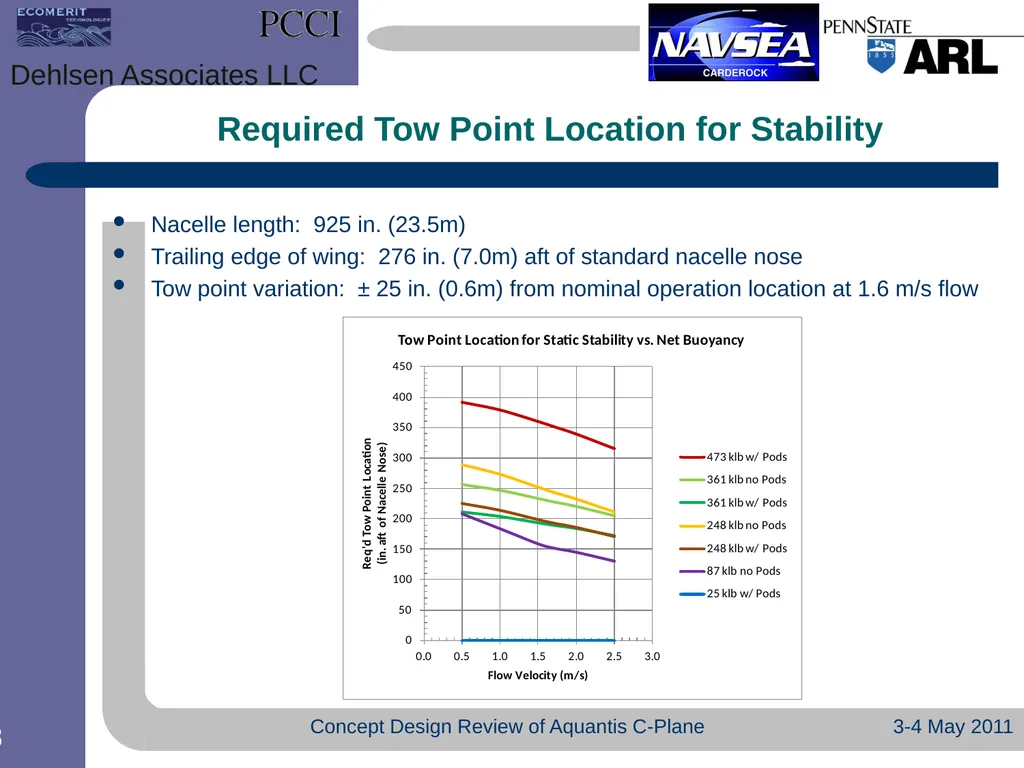
Required Tow Point Location for Stability Nacelle length: 925 in. (23.5m)
Trailing edge of wing: 276 in. (7.0m) aft of standard nacelle nose
Tow point variation: ± 25 in. (0.6m) from nominal operation location at 1.6 m/s flow 3-4 May 2011 Concept Design Review of Aquantis C-Plane Dehlsen Associates LLC<br>
Trailing edge of wing: 276 in. (7.0m) aft of standard nacelle nose
Tow point variation: ± 25 in. (0.6m) from nominal operation location at 1.6 m/s flow 3-4 May 2011 Concept Design Review of Aquantis C-Plane Dehlsen Associates LLC<br>
19
3-4 May 2011 Concept Design Review of Aquantis C-Plane Dehlsen Associates LLC<br>
20
3-4 May 2011 Concept Design Review of Aquantis C-Plane Dehlsen Associates LLC<br>
21
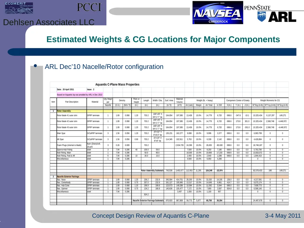
Estimated Weights & CG Locations for Major Components ARL Dec’10 Nacelle/Rotor configuration 3-4 May 2011 Concept Design Review of Aquantis C-Plane Dehlsen Associates LLC<br>
22
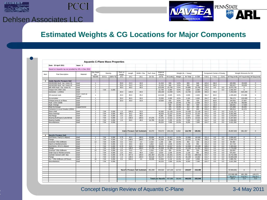
Estimated Weights & CG Locations for Major Components 3-4 May 2011 Concept Design Review of Aquantis C-Plane Dehlsen Associates LLC<br>
23
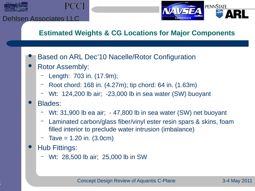
Estimated Weights & CG Locations for Major Components Based on ARL Dec’10 Nacelle/Rotor Configuration
Rotor Assembly:
Length: 703 in. (17.9m);
Root chord: 168 in. (4.27m); tip chord: 64 in. (1.63m)
Wt: 124,200 lb air; -23,000 lb in sea water (SW) buoyant
Blades:
Wt: 31,900 lb ea air; - 47,800 lb in sea water (SW) net buoyant
Laminated carbon/glass fiber/vinyl ester resin spars & skins, foam filled interior to preclude water intrusion (imbalance)
Tave = 1.20 in. (3.0cm)
Hub Fittings:
Wt: 28,500 lb air; 25,000 lb in SW 3-4 May 2011 Concept Design Review of Aquantis C-Plane Dehlsen Associates LLC<br>
Rotor Assembly:
Length: 703 in. (17.9m);
Root chord: 168 in. (4.27m); tip chord: 64 in. (1.63m)
Wt: 124,200 lb air; -23,000 lb in sea water (SW) buoyant
Blades:
Wt: 31,900 lb ea air; - 47,800 lb in sea water (SW) net buoyant
Laminated carbon/glass fiber/vinyl ester resin spars & skins, foam filled interior to preclude water intrusion (imbalance)
Tave = 1.20 in. (3.0cm)
Hub Fittings:
Wt: 28,500 lb air; 25,000 lb in SW 3-4 May 2011 Concept Design Review of Aquantis C-Plane Dehlsen Associates LLC<br>
24
Nacelle Exterior Fairings
Length: 924 in. (23.47m); Outside Diameter: 236 in. (6.0m)
Laminated glass fiber /vinyl ester resin
Tave = 1.00 in. (2.5cm)
Wt: 65,800 lb air: 30,400 lb in SW (heavy)
Drive train, shafting, bearings & hydraulic/electrical equipment internal to the pressure hull
Wt: 116,800 lb air; 116,800 lb in SW (in housing, no displacement)
Pressure Hull (with external T-rib stiffeners)
Diameter: 180 in. (4.57m)
Length: 447 in. (11.35m)
Wt: 139,850 lb air; -318,500 lb in SW (buoyant) 3-4 May 2011 Concept Design Review of Aquantis C-Plane Dehlsen Associates LLC Estimated Weights & CG Locations for Major Components<br>
Length: 924 in. (23.47m); Outside Diameter: 236 in. (6.0m)
Laminated glass fiber /vinyl ester resin
Tave = 1.00 in. (2.5cm)
Wt: 65,800 lb air: 30,400 lb in SW (heavy)
Drive train, shafting, bearings & hydraulic/electrical equipment internal to the pressure hull
Wt: 116,800 lb air; 116,800 lb in SW (in housing, no displacement)
Pressure Hull (with external T-rib stiffeners)
Diameter: 180 in. (4.57m)
Length: 447 in. (11.35m)
Wt: 139,850 lb air; -318,500 lb in SW (buoyant) 3-4 May 2011 Concept Design Review of Aquantis C-Plane Dehlsen Associates LLC Estimated Weights & CG Locations for Major Components<br>
25
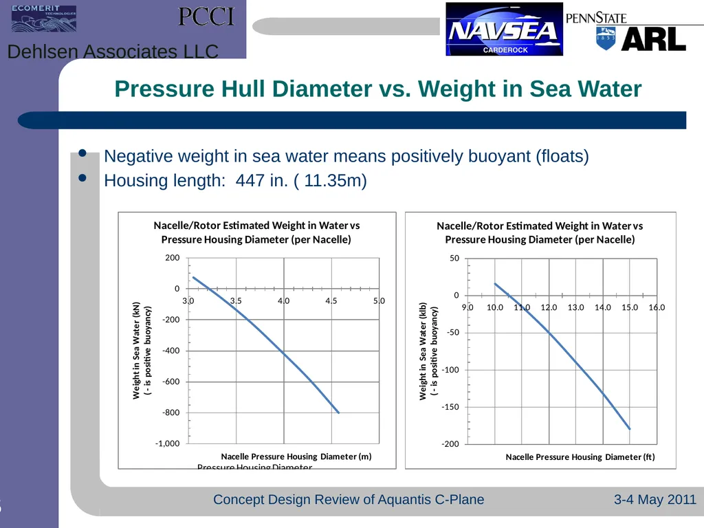
Pressure Hull Diameter vs. Weight in Sea Water Negative weight in sea water means positively buoyant (floats)
Housing length: 447 in. ( 11.35m) 3-4 May 2011 Concept Design Review of Aquantis C-Plane Dehlsen Associates LLC<br>
Housing length: 447 in. ( 11.35m) 3-4 May 2011 Concept Design Review of Aquantis C-Plane Dehlsen Associates LLC<br>
26
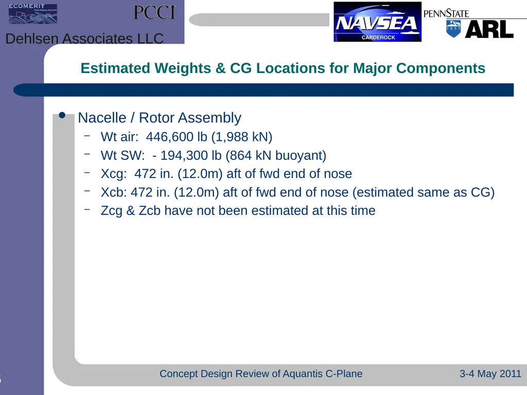
Nacelle / Rotor Assembly
Wt air: 446,600 lb (1,988 kN)
Wt SW: - 194,300 lb (864 kN buoyant)
Xcg: 472 in. (12.0m) aft of fwd end of nose
Xcb: 472 in. (12.0m) aft of fwd end of nose (estimated same as CG)
Zcg & Zcb have not been estimated at this time 3-4 May 2011 Concept Design Review of Aquantis C-Plane Dehlsen Associates LLC Estimated Weights & CG Locations for Major Components<br>
Wt air: 446,600 lb (1,988 kN)
Wt SW: - 194,300 lb (864 kN buoyant)
Xcg: 472 in. (12.0m) aft of fwd end of nose
Xcb: 472 in. (12.0m) aft of fwd end of nose (estimated same as CG)
Zcg & Zcb have not been estimated at this time 3-4 May 2011 Concept Design Review of Aquantis C-Plane Dehlsen Associates LLC Estimated Weights & CG Locations for Major Components<br>
27
3-4 May 2011 Concept Design Review of Aquantis C-Plane Dehlsen Associates LLC<br>
28
3-4 May 2011 Concept Design Review of Aquantis C-Plane Dehlsen Associates LLC<br>
29
3-4 May 2011 Concept Design Review of Aquantis C-Plane Dehlsen Associates LLC<br>