A beamer tutorial LayoutBeamer, from GenISys GmbH is the software we use to convert CAD files in GDS format to the EBPGs GPF format. After reading this, the next assignment will be to convert a pattern; for example, the one you created in
"A beamer tutorial LayoutBeamer, from GenISys GmbH" is the property of its rightful owner. Permission is granted to
download and print the materials on this website for personal, non-commercial use only, and to display it
on your personal computer provided you do not modify the materials and that you retain all copyright
notices contained in the materials. By downloading content from our website, you accept the terms of this
agreement.
Presentation Transcript
01
A beamer tutorial
LayoutBeamer, from GenISys GmbH is the software we use to convert CAD files in GDS format to the EBPG’s GPF format.
After reading this, the next assignment will be to convert a pattern; for example, the one you created in the previous assignment.
You can save some time by doing both at once.<br>
02
Beamer, or “LayoutBeamer” is a program which converts
pattern shapes to machine-specific formats, chopping
polygons into trapezoids, and cutting large patterns at
exposure field boundaries. Patterns will be stitched together
by writing each field, then moving the stage.
Many e-beam systems and mask writers can use the same
pattern fracturing software, and so a company such as GeniSys can provide better support for this common, essential software.
The only competitor to Beamer is “CATS” from Synopsys. CATS was once the defacto standard, and is still used on
many e-beam mask writers. Beamer is much more popular for use with research e-beam systems.<br>
03
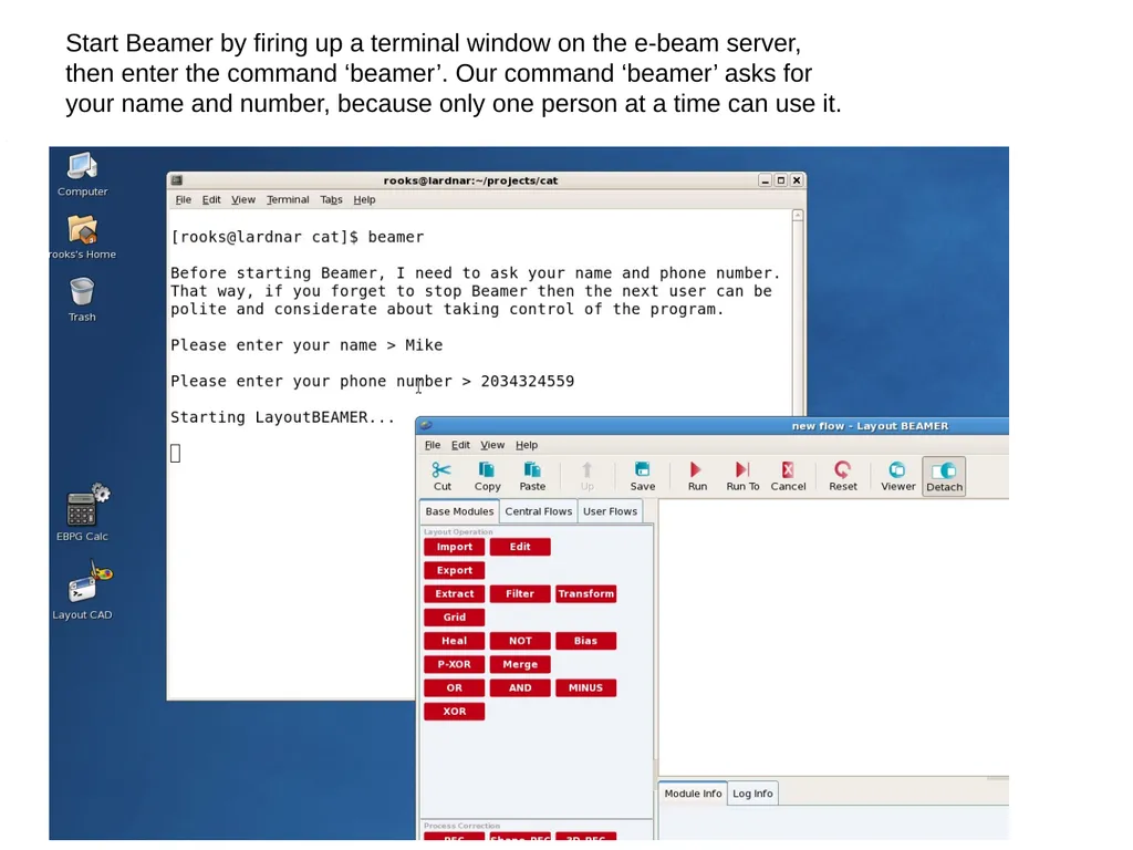
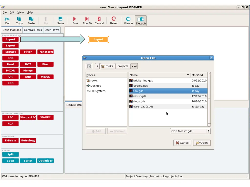
Start Beamer by firing up a terminal window on the e-beam server, then enter the command ‘beamer’. Our command ‘beamer’ asks for your name and number, because only one person at a time can use it.<br>
04
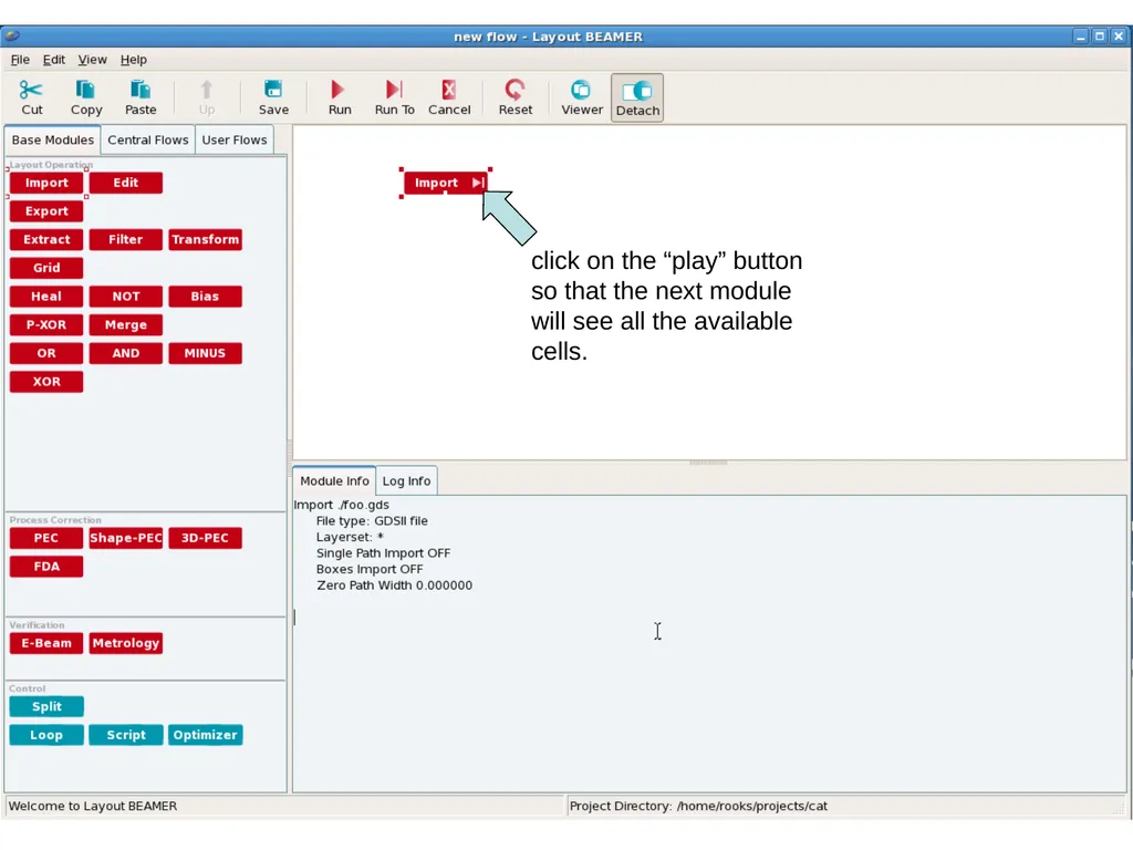
click on the “play” button
so that the next module
will see all the available
cells.<br>
05
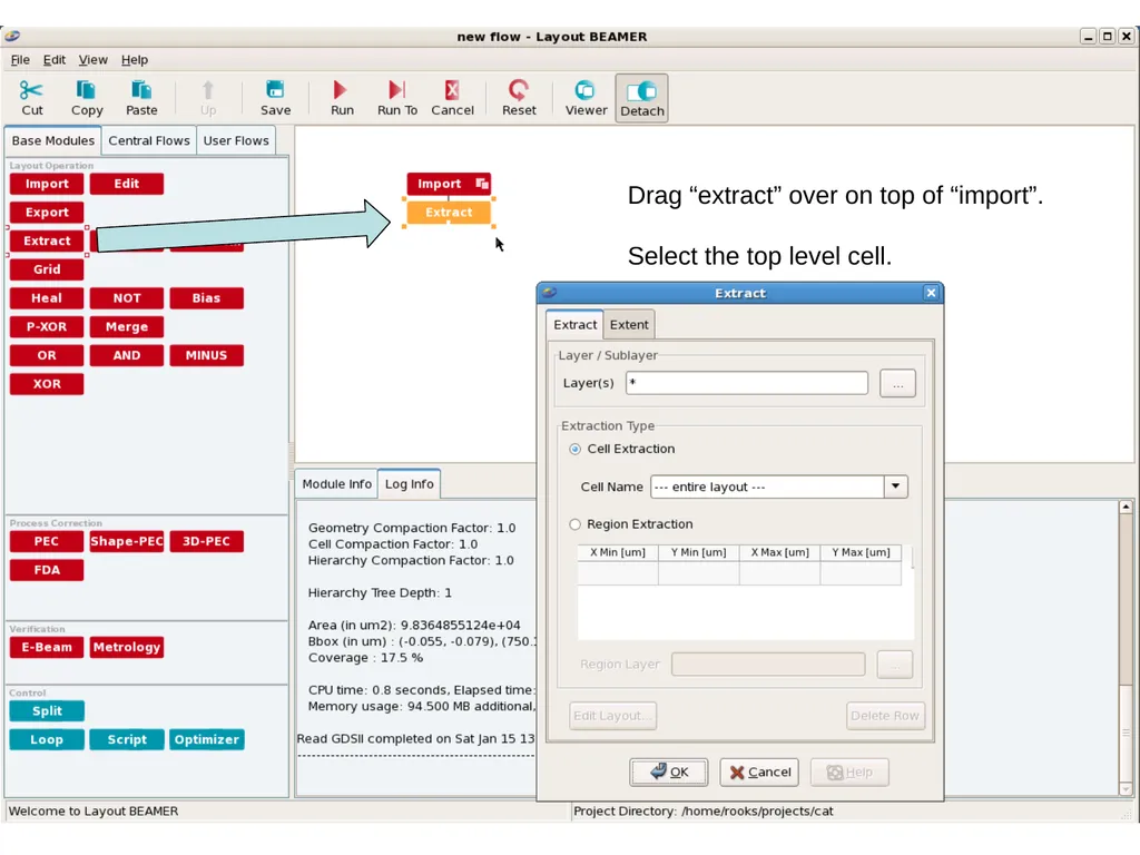
Drag “extract” over on top of “import”.
Select the top level cell.<br>
06
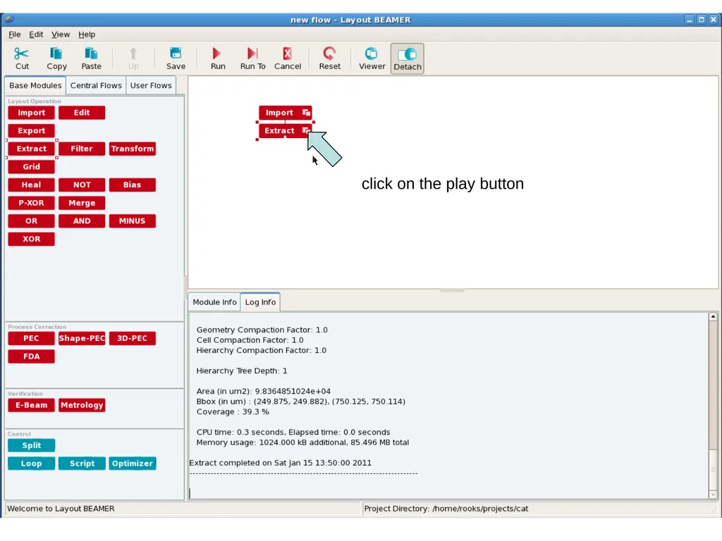
click on the play button<br>
07
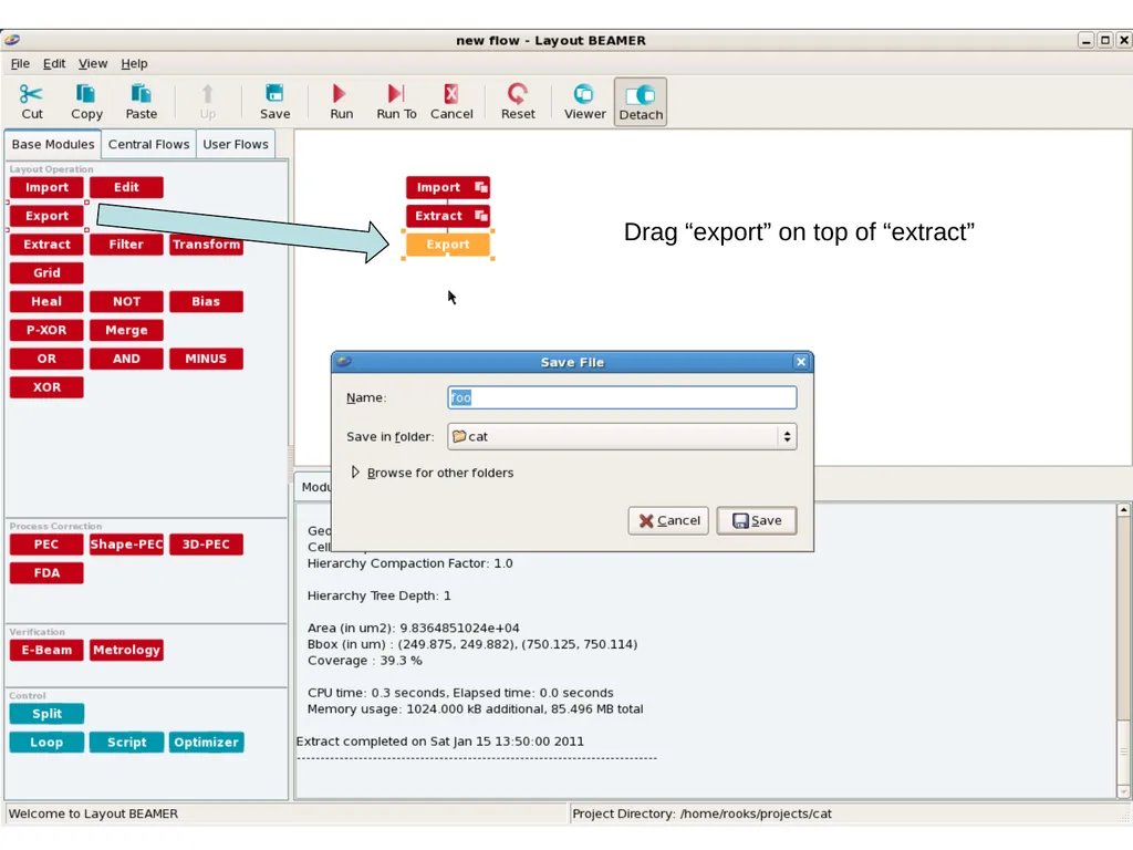
Drag “export” on top of “extract”<br>
08
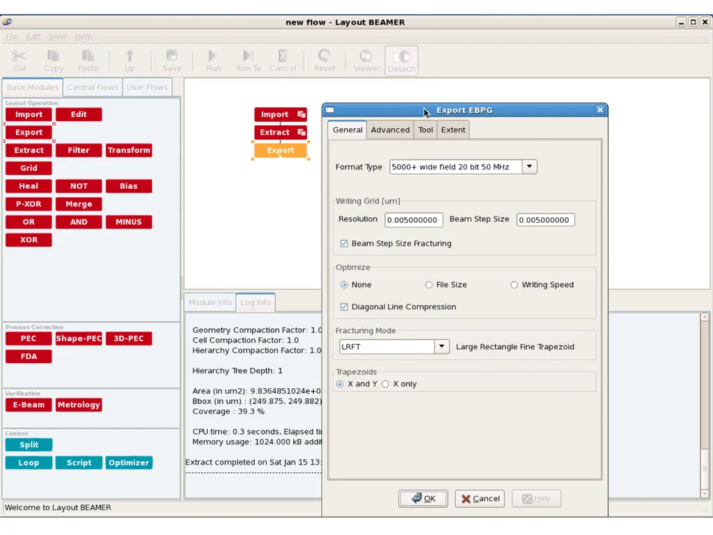
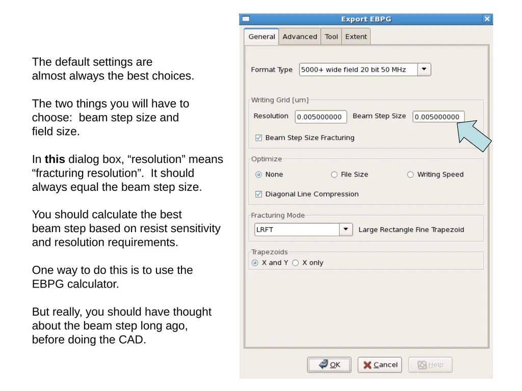
The default settings are
almost always the best choices.
The two things you will have to
choose: beam step size and
field size.
In this dialog box, “resolution” means
“fracturing resolution”. It should
always equal the beam step size.
You should calculate the best
beam step based on resist sensitivity
and resolution requirements.
One way to do this is to use the
EBPG calculator.
But really, you should have thought
about the beam step long ago,
before doing the CAD.<br>
09
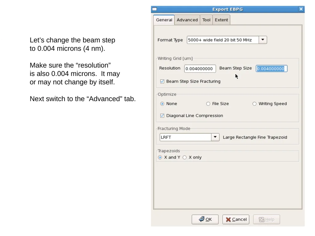
Let’s change the beam step
to 0.004 microns (4 nm).
Make sure the “resolution”
is also 0.004 microns. It may
or may not change by itself.
Next switch to the “Advanced” tab.<br>
10
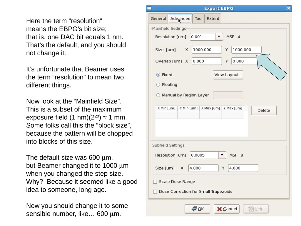
Here the term “resolution”
means the EBPG’s bit size;
that is, one DAC bit equals 1 nm.
That’s the default, and you should
not change it.
It’s unfortunate that Beamer uses
the term “resolution” to mean two
different things.
Now look at the “Mainfield Size”.
This is a subset of the maximum
exposure field (1 nm)(220) ≈ 1 mm.
Some folks call this the “block size”,
because the pattern will be chopped
into blocks of this size.
The default size was 600 mm,
but Beamer changed it to 1000 mm
when you changed the step size.
Why? Because it seemed like a good
idea to someone, long ago.
Now you should change it to some
sensible number, like… 600 mm.<br>
11
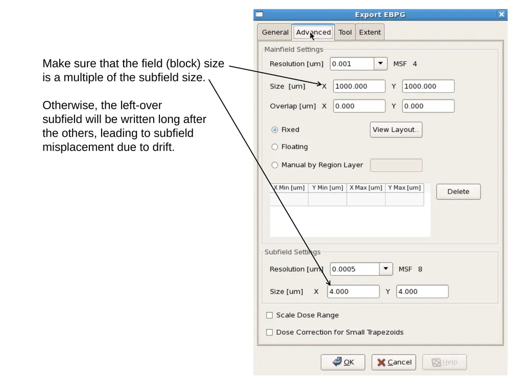
Make sure that the field (block) size
is a multiple of the subfield size.
Otherwise, the left-over
subfield will be written long after
the others, leading to subfield
misplacement due to drift.<br>
12
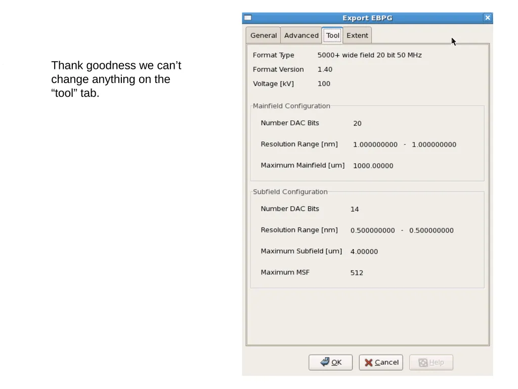
Thank goodness we can’t
change anything on the
“tool” tab.<br>
13
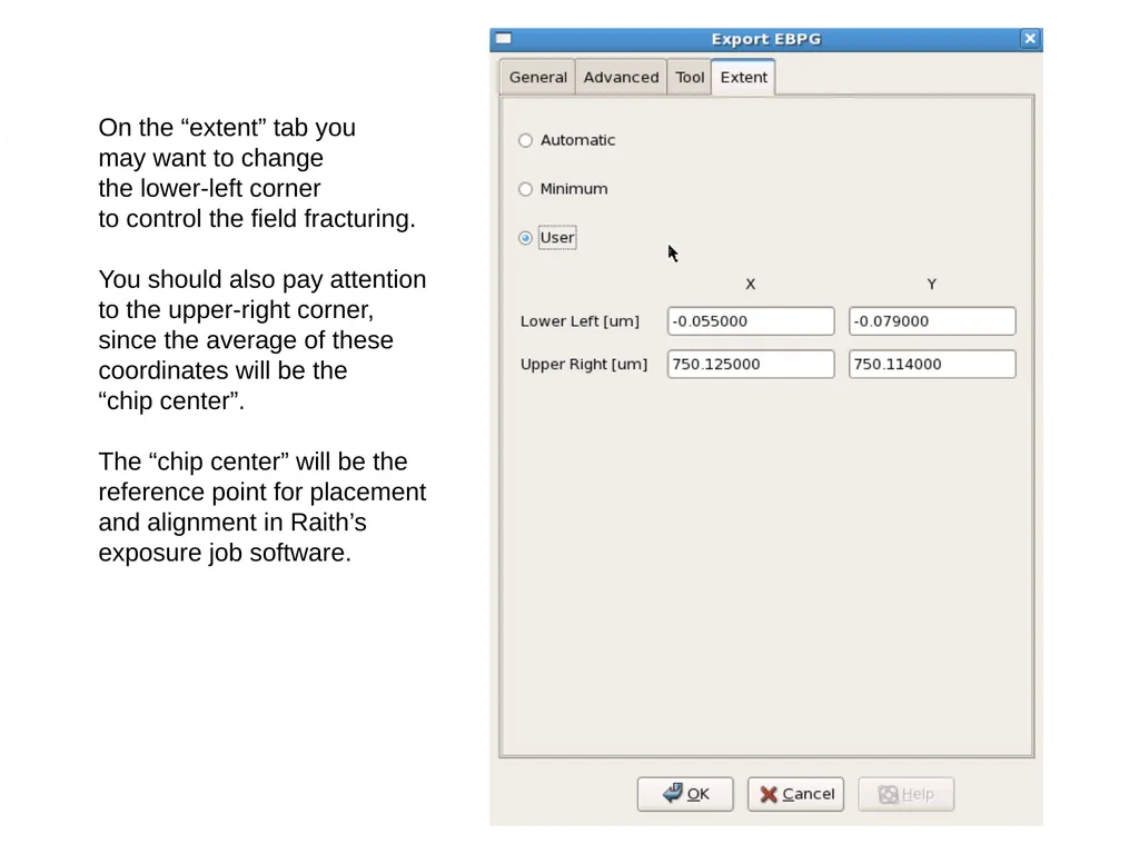
On the “extent” tab you
may want to change
the lower-left corner
to control the field fracturing.
You should also pay attention
to the upper-right corner,
since the average of these
coordinates will be the
“chip center”.
The “chip center” will be the
reference point for placement
and alignment in Raith’s
exposure job software.<br>
14
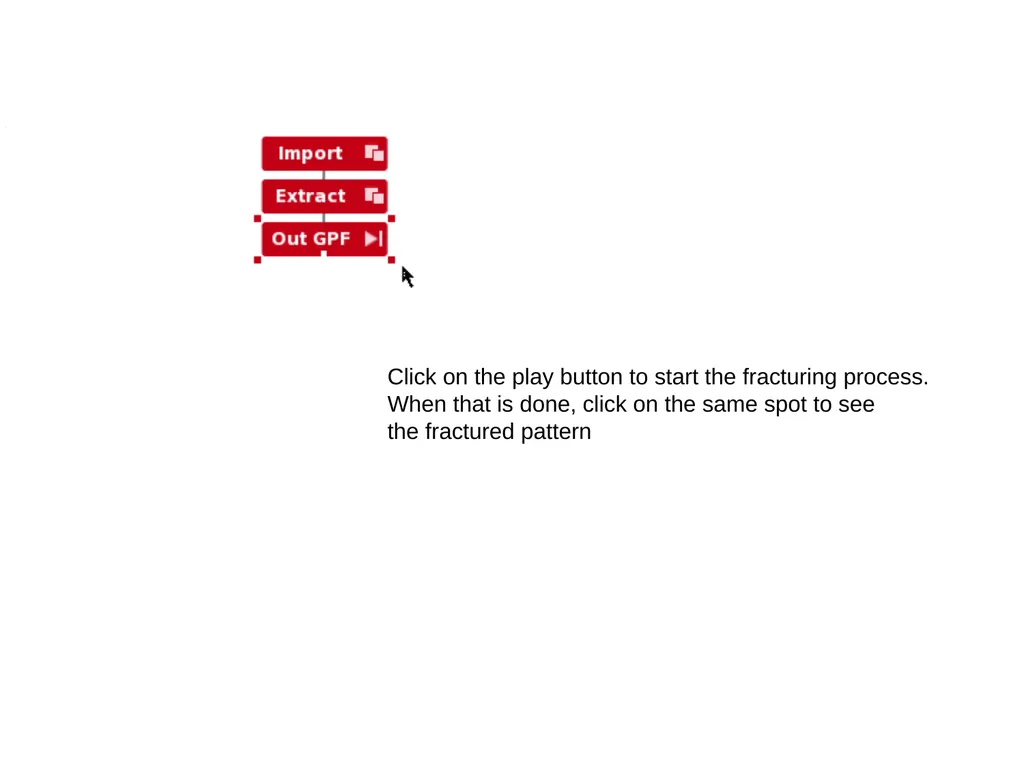
Click on the play button to start the fracturing process.
When that is done, click on the same spot to see
the fractured pattern<br>
15
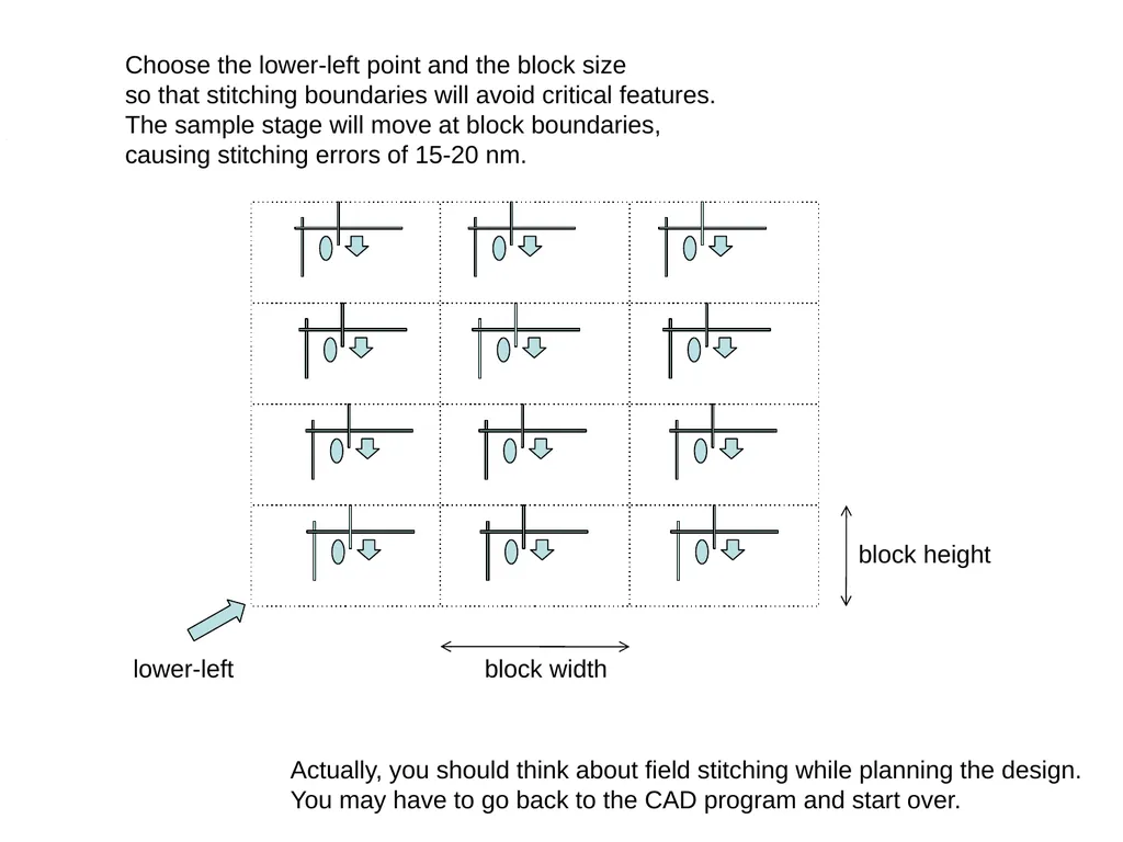
Choose the lower-left point and the block size
so that stitching boundaries will avoid critical features.
The sample stage will move at block boundaries,
causing stitching errors of 15-20 nm. lower-left block width block height Actually, you should think about field stitching while planning the design.
You may have to go back to the CAD program and start over.<br>
16
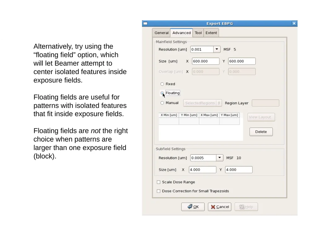
Alternatively, try using the
“floating field” option, which
will let Beamer attempt to
center isolated features inside
exposure fields.
Floating fields are useful for patterns with isolated features that fit inside exposure fields.
Floating fields are not the right choice when patterns are larger than one exposure field (block).<br>
17
Those are the three basic steps you always need:
Import
Extract
Export
But there are all sorts of other things you might need to do.
For example, suppose you need to crop the pattern.
You’ll find that you cannot simply set the lower-left and upper-right
corners in the “export” box. Instead, you’ll need an extra “extract” step.<br>
18
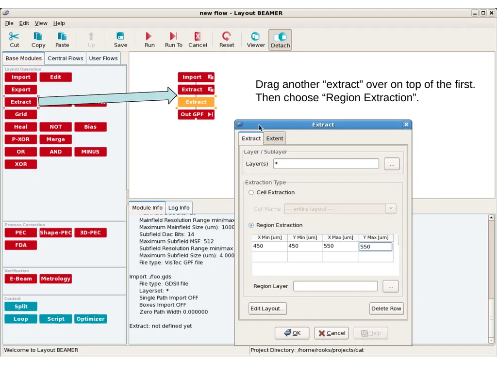
Drag another “extract” over on top of the first.
Then choose “Region Extraction”.<br>
19
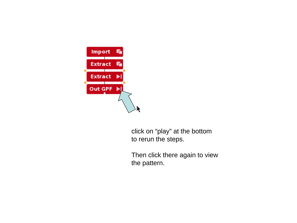
click on “play” at the bottom
to rerun the steps.
Then click there again to view
the pattern.<br>
20
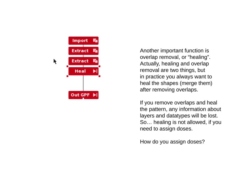
Another important function is
overlap removal, or “healing”.
Actually, healing and overlap
removal are two things, but
in practice you always want to
heal the shapes (merge them)
after removing overlaps.
If you remove overlaps and heal
the pattern, any information about
layers and datatypes will be lost.
So… healing is not allowed, if you
need to assign doses.
How do you assign doses?<br>
21
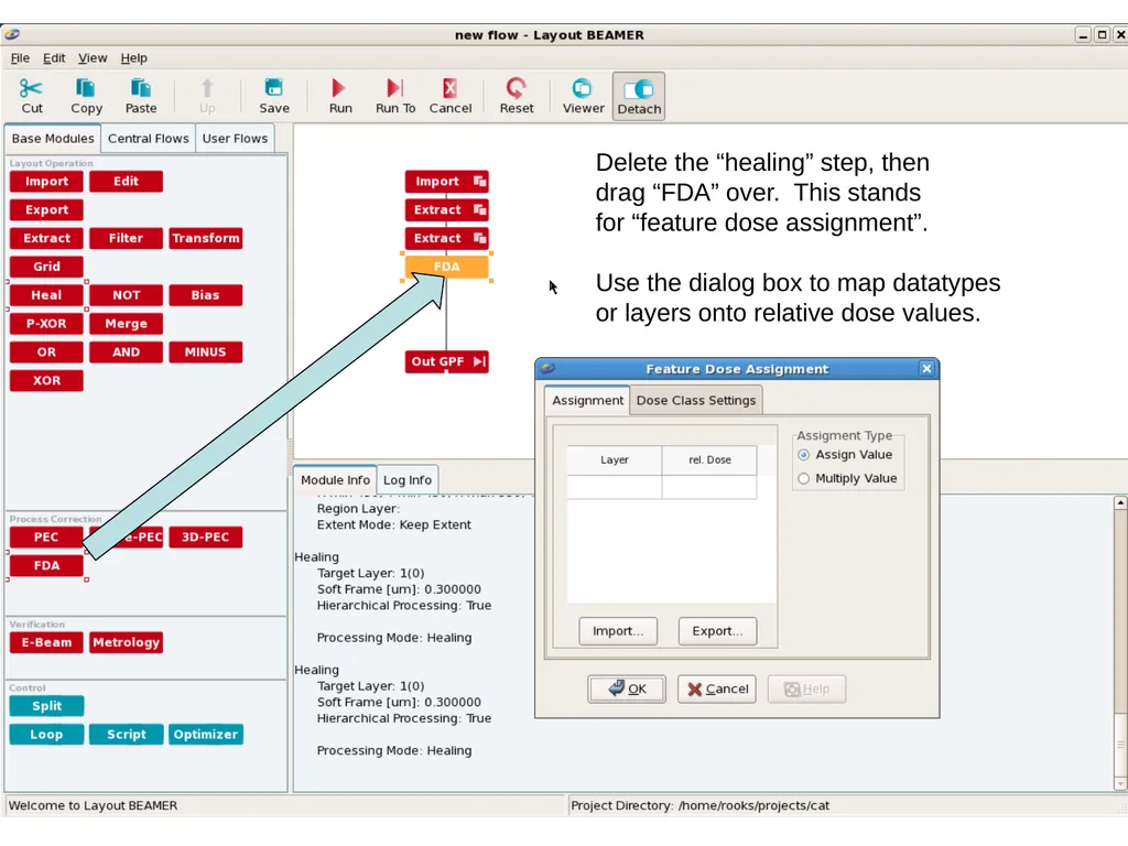
Delete the “healing” step, then
drag “FDA” over. This stands
for “feature dose assignment”.
Use the dialog box to map datatypes
or layers onto relative dose values.<br>
22
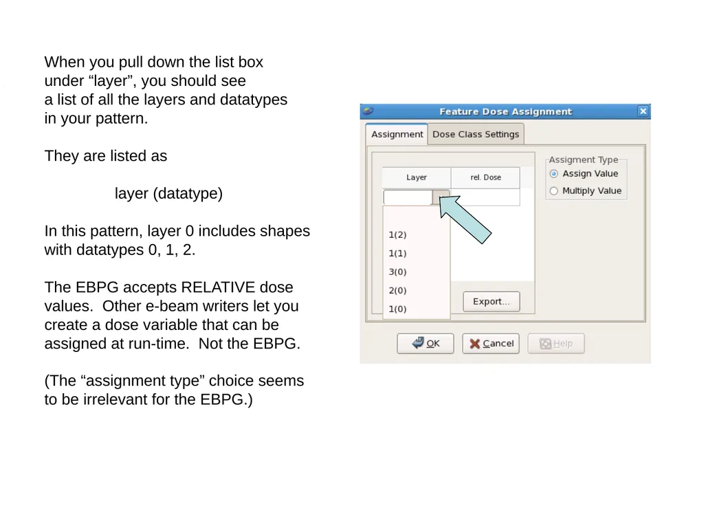
When you pull down the list box
under “layer”, you should see
a list of all the layers and datatypes
in your pattern.
They are listed as
layer (datatype)
In this pattern, layer 0 includes shapes
with datatypes 0, 1, 2.
The EBPG accepts RELATIVE dose
values. Other e-beam writers let you
create a dose variable that can be
assigned at run-time. Not the EBPG.
(The “assignment type” choice seems
to be irrelevant for the EBPG.)<br>
23
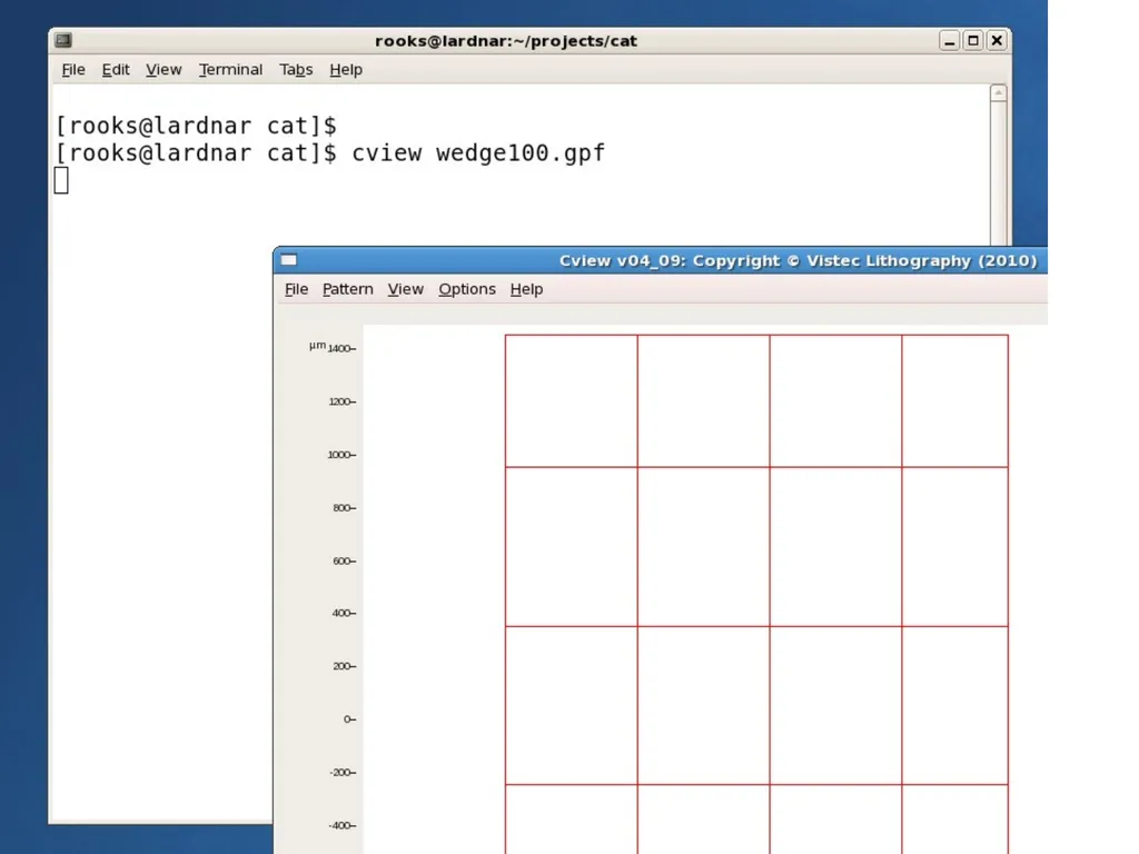
Checking the GPF file with Cview<br>
24
draw
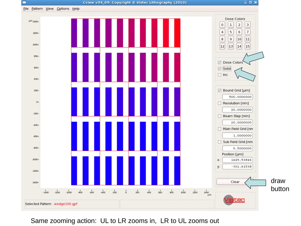
button Same zooming action: UL to LR zooms in, LR to UL zooms out<br>
25
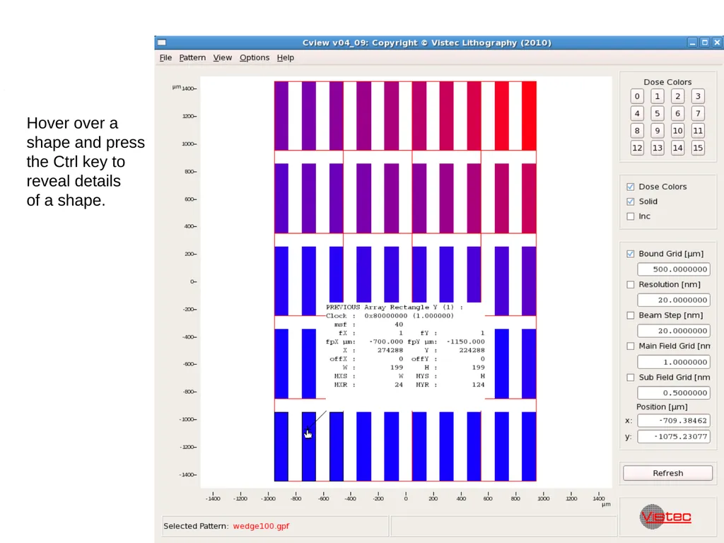
Hover over a
shape and press
the Ctrl key to
reveal details
of a shape.<br>
26
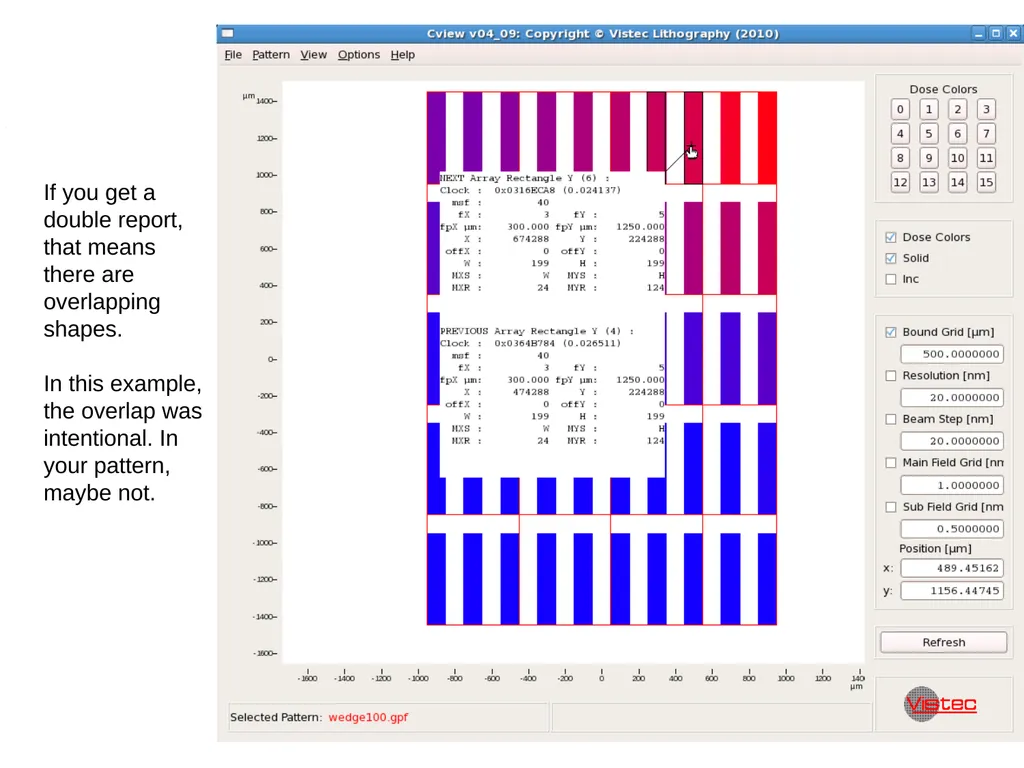
If you get a
double report,
that means
there are
overlapping
shapes.
In this example,
the overlap was
intentional. In
your pattern,
maybe not.<br>
27
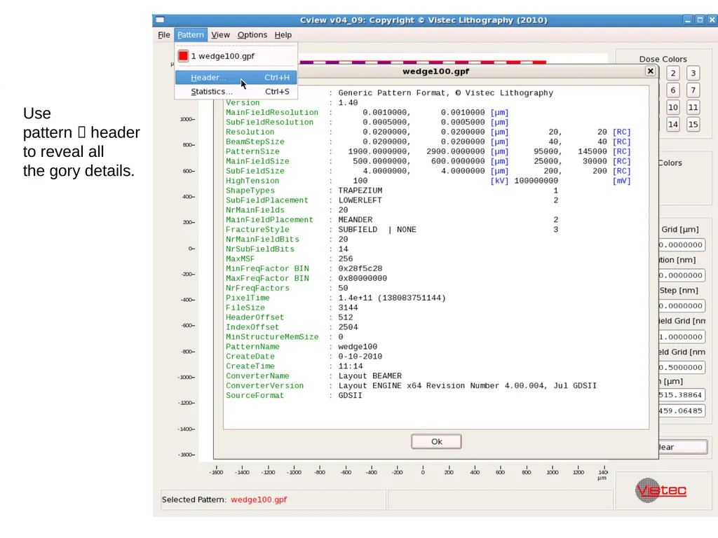
Use
pattern header
to reveal all
the gory details.<br>