
An Overview of Reference Frames and Coordinate
GB
Published · 29 slides · 0 views
1 / 1
Description
An Overview of Reference Frames and Coordinate Systems in the SPICE Context April 2023 Purpose of this Tutorial This tutorial provides an overview of reference frames and coordinate systems. It contains conventions specific to SPICE.
Related Topics
Share
Embed code
Download this presentation From Below
"An Overview of Reference Frames and Coordinate" is the property of its rightful owner. Permission is granted to download and print the materials on this website for personal, non-commercial use only, and to display it on your personal computer provided you do not modify the materials and that you retain all copyright notices contained in the materials. By downloading content from our website, you accept the terms of this agreement.
Presentation Transcript
01
An Overview of
Reference Frames
and
Coordinate Systems
in the SPICE Context April 2023<br>
02
Purpose of this Tutorial This tutorial provides an overview of reference frames and coordinate systems.
It contains conventions specific to SPICE.
Details about the SPICE Frames subsystem are found in other tutorials and one document:
FK (tutorial)
Using Frames (tutorial)
Dynamic Frames (advanced tutorial)
Frames Required Reading (technical reference)
Details about SPICE coordinate systems are found in API module headers for coordinate conversion routines. Frames and Coordinate Systems 2<br>
It contains conventions specific to SPICE.
Details about the SPICE Frames subsystem are found in other tutorials and one document:
FK (tutorial)
Using Frames (tutorial)
Dynamic Frames (advanced tutorial)
Frames Required Reading (technical reference)
Details about SPICE coordinate systems are found in API module headers for coordinate conversion routines. Frames and Coordinate Systems 2<br>
03
A Challenge Next to “time,” the topics of reference frames and coordinate systems present some of the largest challenges to documenting and understanding observation geometry. Contributing factors are …
differences in definitions, lack of concise definitions, and special cases
evolution of the frames subsystem within SPICE
the substantial frames management capabilities within SPICE
NAIF hopes this tutorial will provide some clarity on these subjects within the SPICE context.
Definitions and terminology used herein may not be consistent with those found elsewhere. Frames and Coordinate Systems 3<br>
differences in definitions, lack of concise definitions, and special cases
evolution of the frames subsystem within SPICE
the substantial frames management capabilities within SPICE
NAIF hopes this tutorial will provide some clarity on these subjects within the SPICE context.
Definitions and terminology used herein may not be consistent with those found elsewhere. Frames and Coordinate Systems 3<br>
04
Frames and Coordinate Systems The definitions below are used within SPICE.
A reference frame (or simply “frame”) is specified by an ordered set of three mutually orthogonal, possibly time dependent, unit-length direction vectors.
A reference frame has an associated center.
In some documentation external to SPICE, this is called a “coordinate frame.”
A coordinate system specifies a mechanism for locating points within a reference frame.
When producing or using state (position and velocity) or orientation (pointing) data, one needs to understand both the reference frame and the coordinate system being used. SPICE Definitions 4<br>
A reference frame (or simply “frame”) is specified by an ordered set of three mutually orthogonal, possibly time dependent, unit-length direction vectors.
A reference frame has an associated center.
In some documentation external to SPICE, this is called a “coordinate frame.”
A coordinate system specifies a mechanism for locating points within a reference frame.
When producing or using state (position and velocity) or orientation (pointing) data, one needs to understand both the reference frame and the coordinate system being used. SPICE Definitions 4<br>
05
Reference Frames<br>
06
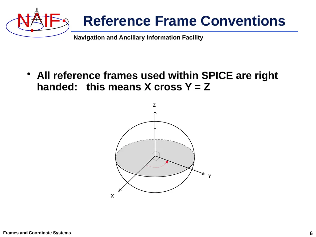
Reference Frame Conventions All reference frames used within SPICE are right handed: this means X cross Y = Z Frames and Coordinate Systems X Y Z 6<br>
07
Frames and Coordinate Systems A reference frame’s center must be a SPICE ephemeris object whose location is coincident with the origin (0, 0, 0) of the frame.
The center of any inertial frame is ALWAYS the solar system barycenter.*
The center of a body-fixed frame is the center of the body.
“Body” means a natural body: sun, planet, satellite, comet, asteroid.
The location of the “body” center is specified using an SPK file.
The center of a topocentric, spacecraft or instrument frame is also an object for which the location is specified by an SPK file.
A frame’s center may play a role in specification of states.
The location of the origin cancels out when doing vector subtraction, but the center is used in computing light time to the center of any non-inertial frame being used Reference Frame Center *True even for inertial frames associated with accelerated bodies, such as the MARSIAU frame. 7<br>
The center of any inertial frame is ALWAYS the solar system barycenter.*
The center of a body-fixed frame is the center of the body.
“Body” means a natural body: sun, planet, satellite, comet, asteroid.
The location of the “body” center is specified using an SPK file.
The center of a topocentric, spacecraft or instrument frame is also an object for which the location is specified by an SPK file.
A frame’s center may play a role in specification of states.
The location of the origin cancels out when doing vector subtraction, but the center is used in computing light time to the center of any non-inertial frame being used Reference Frame Center *True even for inertial frames associated with accelerated bodies, such as the MARSIAU frame. 7<br>
08
Frames and Coordinate Systems Inertial
Non-rotating with respect to stars
Non-accelerating origin
Velocity is typically non-zero, but acceleration is negligible
Examples:
J2000 (also known as EME 2000, and is generally used in SPICE to refer to the ICRF)
ECLIPJ2000 Types of Reference Frames - 1 8<br>
Non-rotating with respect to stars
Non-accelerating origin
Velocity is typically non-zero, but acceleration is negligible
Examples:
J2000 (also known as EME 2000, and is generally used in SPICE to refer to the ICRF)
ECLIPJ2000 Types of Reference Frames - 1 8<br>
09
Frames and Coordinate Systems Non-Inertial
Accelerating, including by rotation
Examples
Body-fixed
Associated with a natural body (e.g. planets, satellites)
Topocentric
Associated with an object on or near the surface of a natural body (e.g. DSN station, rover)
Spacecraft
Associated with the main spacecraft structure (the “bus”)
Instrument
One or more frames are usually associated with each instrument
Also applicable to a spacecraft antenna, solar array, etc.
Dynamic
A special family of frames unique to SPICE
These have time-dependent orientation
But this category does not include frames for which the orientation is provided using a C-kernel (CK) or a PC-kernel (PCK) Types of Reference Frames - 2 CK ≈ spacecraft orientation; PCK ≈ natural body orientation 9<br>
Accelerating, including by rotation
Examples
Body-fixed
Associated with a natural body (e.g. planets, satellites)
Topocentric
Associated with an object on or near the surface of a natural body (e.g. DSN station, rover)
Spacecraft
Associated with the main spacecraft structure (the “bus”)
Instrument
One or more frames are usually associated with each instrument
Also applicable to a spacecraft antenna, solar array, etc.
Dynamic
A special family of frames unique to SPICE
These have time-dependent orientation
But this category does not include frames for which the orientation is provided using a C-kernel (CK) or a PC-kernel (PCK) Types of Reference Frames - 2 CK ≈ spacecraft orientation; PCK ≈ natural body orientation 9<br>
10
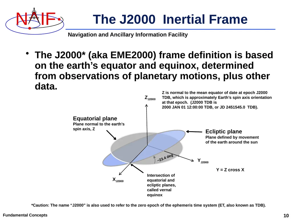
The J2000 Inertial Frame The J2000* (aka EME2000) frame definition is based on the earth’s equator and equinox, determined from observations of planetary motions, plus other data. Fundamental Concepts 10 Ecliptic plane
Plane defined by movement of the earth around the sun Equatorial plane
Plane normal to the earth’s spin axis, Z Intersection of
equatorial and
ecliptic planes,
called vernal
equinox ZJ2000 XJ2000 YJ2000 ~23.4 deg Y = Z cross X *Caution: The name “J2000” is also used to refer to the zero epoch of the ephemeris time system (ET, also known as TDB). Z is normal to the mean equator of date at epoch J2000 TDB, which is approximately Earth’s spin axis orientation at that epoch. (J2000 TDB is
2000 JAN 01 12:00:00 TDB, or JD 2451545.0 TDB).<br>
Plane defined by movement of the earth around the sun Equatorial plane
Plane normal to the earth’s spin axis, Z Intersection of
equatorial and
ecliptic planes,
called vernal
equinox ZJ2000 XJ2000 YJ2000 ~23.4 deg Y = Z cross X *Caution: The name “J2000” is also used to refer to the zero epoch of the ephemeris time system (ET, also known as TDB). Z is normal to the mean equator of date at epoch J2000 TDB, which is approximately Earth’s spin axis orientation at that epoch. (J2000 TDB is
2000 JAN 01 12:00:00 TDB, or JD 2451545.0 TDB).<br>
11
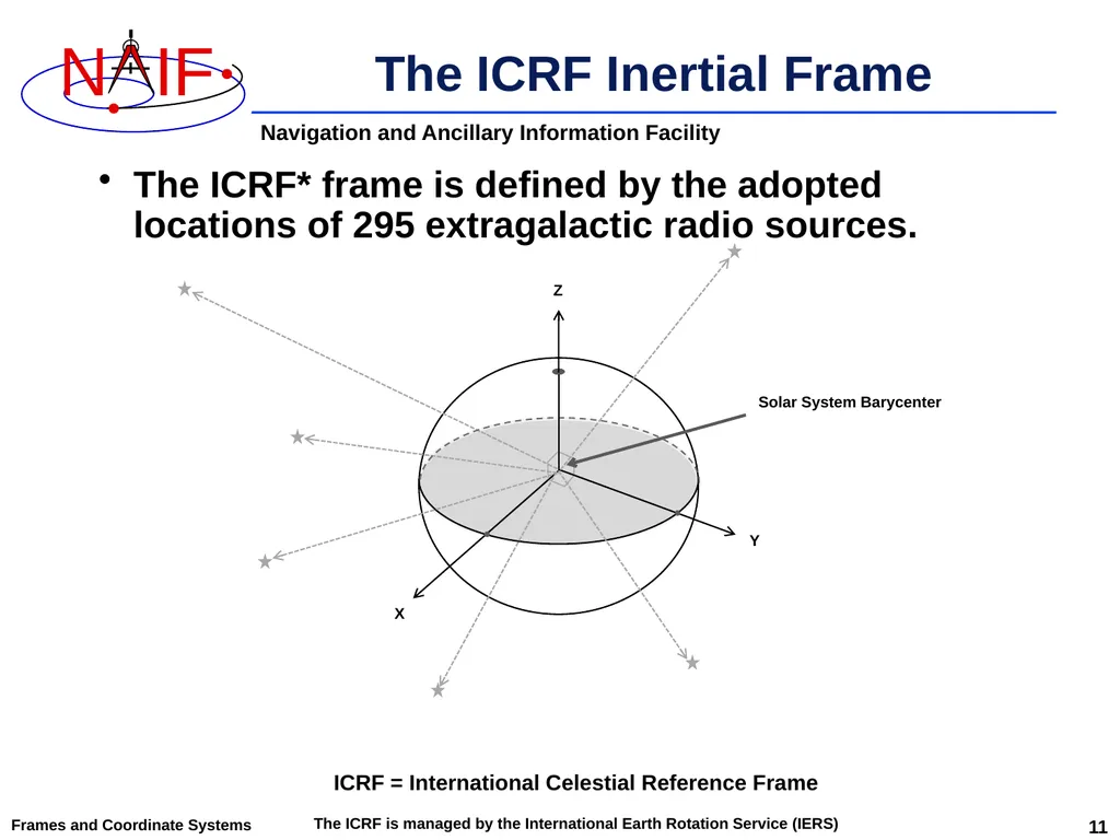
The ICRF Inertial Frame The ICRF* frame is defined by the adopted locations of 295 extragalactic radio sources. Frames and Coordinate Systems X Y Z Solar System Barycenter ICRF = International Celestial Reference Frame
The ICRF is managed by the International Earth Rotation Service (IERS) 11<br>
The ICRF is managed by the International Earth Rotation Service (IERS) 11<br>
12
J2000 versus ICRF The realization of ICRF was made to coincide almost exactly with the J2000 frame.
The difference is very small–a rotation of less than 0.1 arc second.
The reference frame name "J2000" is generally used in SPICE as a label for the ICRF frame.
In reality, any SPICE data said to be referenced to the J2000 frame are actually referenced to the ICRF frame.
Except for attitude derived from the 1976 IAU Earth precession model and 1980 IAU Earth nutation and mean obliquity of date models
For historical and backwards compatibility reasons, only the name “J2000” is recognized by SPICE software as a frame name–not “ICRF.”
No transformation is required to convert SPICE state vectors or orientation data from the J2000 frame to the ICRF. Frames and Coordinate Systems 12<br>
The difference is very small–a rotation of less than 0.1 arc second.
The reference frame name "J2000" is generally used in SPICE as a label for the ICRF frame.
In reality, any SPICE data said to be referenced to the J2000 frame are actually referenced to the ICRF frame.
Except for attitude derived from the 1976 IAU Earth precession model and 1980 IAU Earth nutation and mean obliquity of date models
For historical and backwards compatibility reasons, only the name “J2000” is recognized by SPICE software as a frame name–not “ICRF.”
No transformation is required to convert SPICE state vectors or orientation data from the J2000 frame to the ICRF. Frames and Coordinate Systems 12<br>
13
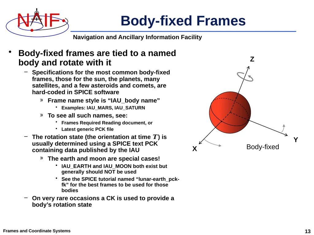
Frames and Coordinate Systems Body-fixed frames are tied to a named body and rotate with it
Specifications for the most common body-fixed frames, those for the sun, the planets, many satellites, and a few asteroids and comets, are hard-coded in SPICE software
Frame name style is “IAU_body name”
Examples: IAU_MARS, IAU_SATURN
To see all such names, see:
Frames Required Reading document, or
Latest generic PCK file
The rotation state (the orientation at time 𝑻) is usually determined using a SPICE text PCK containing data published by the IAU
The earth and moon are special cases!
IAU_EARTH and IAU_MOON both exist but generally should NOT be used
See the SPICE tutorial named “lunar-earth_pck-fk” for the best frames to be used for those bodies
On very rare occasions a CK is used to provide a body’s rotation state Body-fixed Frames Z Y X • • Body-fixed • 13<br>
Specifications for the most common body-fixed frames, those for the sun, the planets, many satellites, and a few asteroids and comets, are hard-coded in SPICE software
Frame name style is “IAU_body name”
Examples: IAU_MARS, IAU_SATURN
To see all such names, see:
Frames Required Reading document, or
Latest generic PCK file
The rotation state (the orientation at time 𝑻) is usually determined using a SPICE text PCK containing data published by the IAU
The earth and moon are special cases!
IAU_EARTH and IAU_MOON both exist but generally should NOT be used
See the SPICE tutorial named “lunar-earth_pck-fk” for the best frames to be used for those bodies
On very rare occasions a CK is used to provide a body’s rotation state Body-fixed Frames Z Y X • • Body-fixed • 13<br>
14
A Caution for Mars The body-fixed frame for Mars is named IAU_MARS
This follows the SPICE naming standard for such frames
However, there also exists in SPICE an inertial frame associated with Mars, named “MARSIAU”
This frame was defined 20 years ago based on old Mars rotation constants, for use by the Mars Observer and Mars Global Surveyor projects
This frame has NO relationship to the similarly sounding IAU_MARS frame, other than that they both relate to Mars Frames and Coordinate Systems 14<br>
This follows the SPICE naming standard for such frames
However, there also exists in SPICE an inertial frame associated with Mars, named “MARSIAU”
This frame was defined 20 years ago based on old Mars rotation constants, for use by the Mars Observer and Mars Global Surveyor projects
This frame has NO relationship to the similarly sounding IAU_MARS frame, other than that they both relate to Mars Frames and Coordinate Systems 14<br>
15
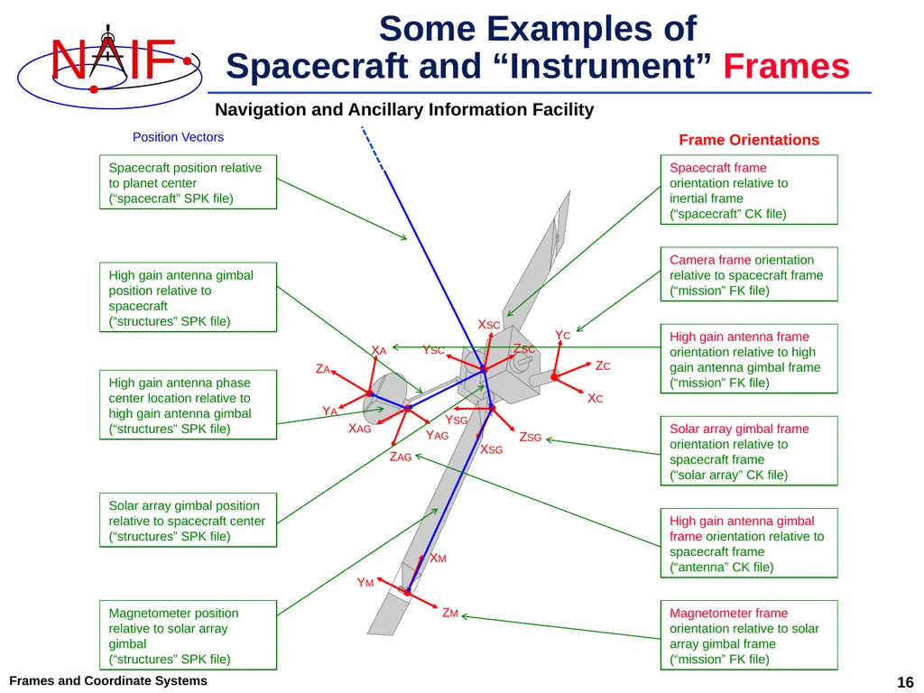
Frames and Coordinate Systems Defined for spacecraft, and items attached to a spacecraft, such as antennas, solar arrays, scan platforms, instruments and moving parts of an instrument (e.g. a scanning mirror)
For those frames that are time varying (“moving”), the frame name is usually defined in an FK and the frame orientation data are usually provided by a CK
For those frames that are not moving (what we call “fixed offset”) both the frame name and the actual data defining the fixed orientation of the frame are provided in an FK Spacecraft and Instrument Frames 15<br>
For those frames that are time varying (“moving”), the frame name is usually defined in an FK and the frame orientation data are usually provided by a CK
For those frames that are not moving (what we call “fixed offset”) both the frame name and the actual data defining the fixed orientation of the frame are provided in an FK Spacecraft and Instrument Frames 15<br>
16
Some Examples of
Spacecraft and “Instrument” Frames Frames and Coordinate Systems 16<br>
17
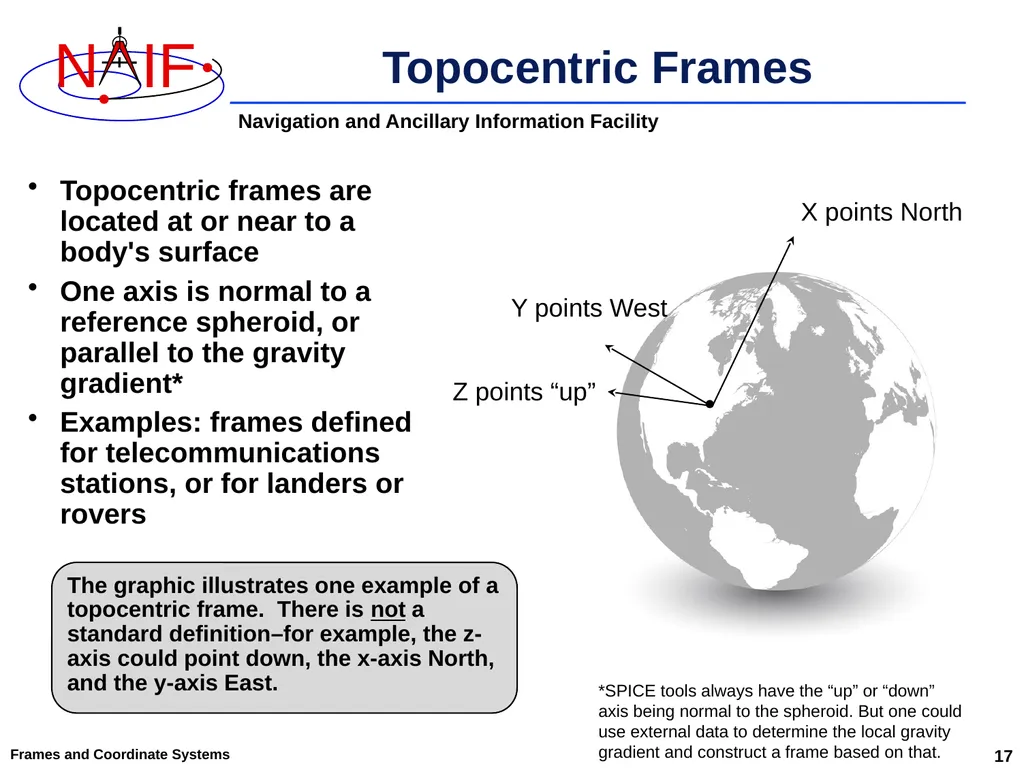
Frames and Coordinate Systems Topocentric frames are located at or near to a body's surface
One axis is normal to a reference spheroid, or parallel to the gravity gradient*
Examples: frames defined for telecommunications stations, or for landers or rovers X points North Topocentric Frames Y points West Z points “up” The graphic illustrates one example of a topocentric frame. There is not a standard definition–for example, the z-axis could point down, the x-axis North, and the y-axis East. • *SPICE tools always have the “up” or “down” axis being normal to the spheroid. But one could use external data to determine the local gravity gradient and construct a frame based on that. 17<br>
One axis is normal to a reference spheroid, or parallel to the gravity gradient*
Examples: frames defined for telecommunications stations, or for landers or rovers X points North Topocentric Frames Y points West Z points “up” The graphic illustrates one example of a topocentric frame. There is not a standard definition–for example, the z-axis could point down, the x-axis North, and the y-axis East. • *SPICE tools always have the “up” or “down” axis being normal to the spheroid. But one could use external data to determine the local gravity gradient and construct a frame based on that. 17<br>
18
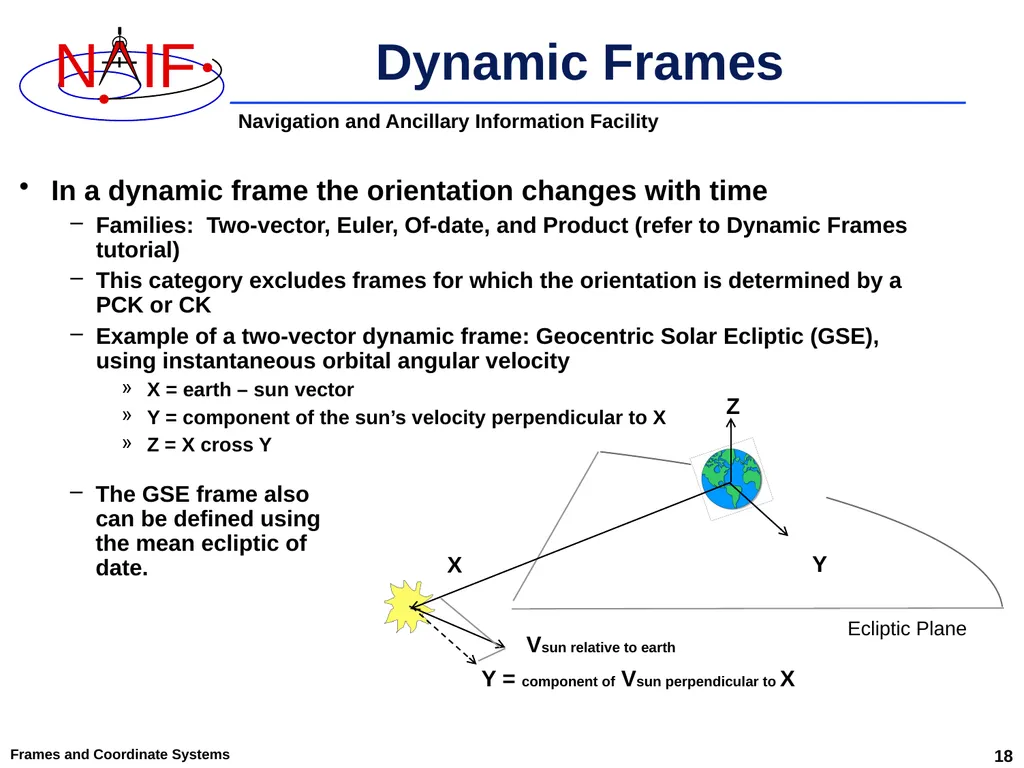
Frames and Coordinate Systems 18 Dynamic Frames In a dynamic frame the orientation changes with time
Families: Two-vector, Euler, Of-date, and Product (refer to Dynamic Frames tutorial)
This category excludes frames for which the orientation is determined by a PCK or CK
Example of a two-vector dynamic frame: Geocentric Solar Ecliptic (GSE), using instantaneous orbital angular velocity
X = earth – sun vector
Y = component of the sun’s velocity perpendicular to X
Z = X cross Y Ecliptic Plane Vsun relative to earth X Y = component of Vsun perpendicular to X Y Z The GSE frame also can be defined using the mean ecliptic of date.<br>
Families: Two-vector, Euler, Of-date, and Product (refer to Dynamic Frames tutorial)
This category excludes frames for which the orientation is determined by a PCK or CK
Example of a two-vector dynamic frame: Geocentric Solar Ecliptic (GSE), using instantaneous orbital angular velocity
X = earth – sun vector
Y = component of the sun’s velocity perpendicular to X
Z = X cross Y Ecliptic Plane Vsun relative to earth X Y = component of Vsun perpendicular to X Y Z The GSE frame also can be defined using the mean ecliptic of date.<br>
19
Coordinate Systems<br>
20
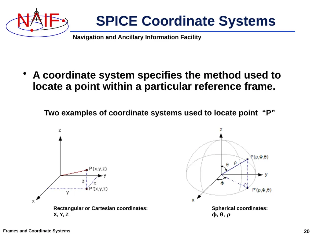
Frames and Coordinate Systems A coordinate system specifies the method used to locate a point within a particular reference frame. SPICE Coordinate Systems Rectangular or Cartesian coordinates:
X, Y, Z Spherical coordinates:
𝛟, 𝛉, 𝝆 Two examples of coordinate systems used to locate point “P” 20<br>
X, Y, Z Spherical coordinates:
𝛟, 𝛉, 𝝆 Two examples of coordinate systems used to locate point “P” 20<br>
21
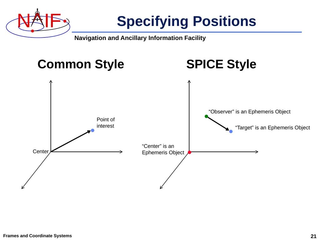
Specifying Positions Common Style SPICE Style Center • Point of
interest • “Target” is an Ephemeris Object • “Observer” is an Ephemeris Object • “Center” is an
Ephemeris Object Frames and Coordinate Systems 21<br>
interest • “Target” is an Ephemeris Object • “Observer” is an Ephemeris Object • “Center” is an
Ephemeris Object Frames and Coordinate Systems 21<br>
22
Many Coordinate Systems Used In the Planetary Science discipline there are a number of coordinate systems in use, just as there are quite a few reference frames in use.
Some of these coordinate systems have well accepted standard definitions, while others are anything but standard.
This means data producers and especially data users need to pay close attention to what they are doing! Frames and Coordinate Systems 22<br>
Some of these coordinate systems have well accepted standard definitions, while others are anything but standard.
This means data producers and especially data users need to pay close attention to what they are doing! Frames and Coordinate Systems 22<br>
23
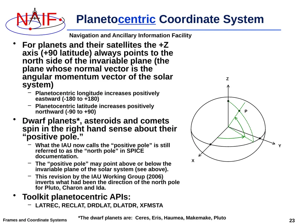
Frames and Coordinate Systems Planetocentric Coordinate System For planets and their satellites the +Z axis (+90 latitude) always points to the north side of the invariable plane (the plane whose normal vector is the angular momentum vector of the solar system)
Planetocentric longitude increases positively eastward (-180 to +180)
Planetocentric latitude increases positively northward (-90 to +90)
Dwarf planets*, asteroids and comets spin in the right hand sense about their “positive pole.”
What the IAU now calls the “positive pole” is still referred to as the “north pole” in SPICE documentation.
The “positive pole” may point above or below the invariable plane of the solar system (see above).
This revision by the IAU Working Group (2006) inverts what had been the direction of the north pole for Pluto, Charon and Ida.
Toolkit planetocentric APIs:
LATREC, RECLAT, DRDLAT, DLATDR, XFMSTA *The dwarf planets are: Ceres, Eris, Haumea, Makemake, Pluto X Y Z P 23<br>
Planetocentric longitude increases positively eastward (-180 to +180)
Planetocentric latitude increases positively northward (-90 to +90)
Dwarf planets*, asteroids and comets spin in the right hand sense about their “positive pole.”
What the IAU now calls the “positive pole” is still referred to as the “north pole” in SPICE documentation.
The “positive pole” may point above or below the invariable plane of the solar system (see above).
This revision by the IAU Working Group (2006) inverts what had been the direction of the north pole for Pluto, Charon and Ida.
Toolkit planetocentric APIs:
LATREC, RECLAT, DRDLAT, DLATDR, XFMSTA *The dwarf planets are: Ceres, Eris, Haumea, Makemake, Pluto X Y Z P 23<br>
24
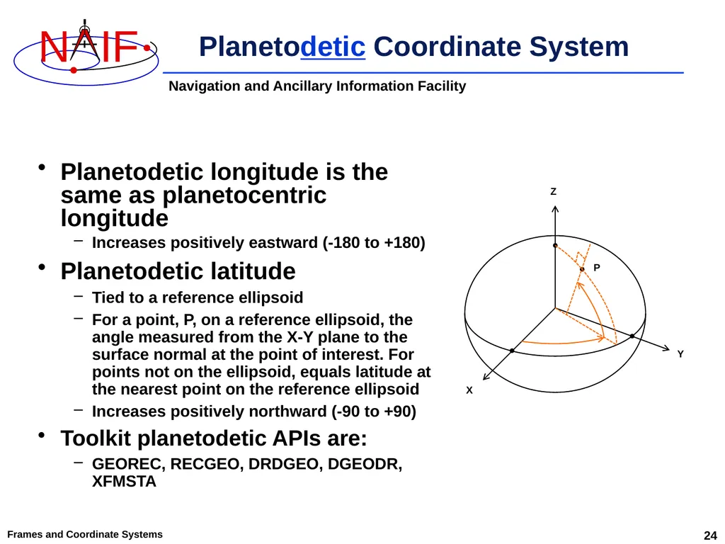
Frames and Coordinate Systems Planetodetic Coordinate System Planetodetic longitude is the same as planetocentric longitude
Increases positively eastward (-180 to +180)
Planetodetic latitude
Tied to a reference ellipsoid
For a point, P, on a reference ellipsoid, the angle measured from the X-Y plane to the surface normal at the point of interest. For points not on the ellipsoid, equals latitude at the nearest point on the reference ellipsoid
Increases positively northward (-90 to +90)
Toolkit planetodetic APIs are:
GEOREC, RECGEO, DRDGEO, DGEODR, XFMSTA X Y Z P 24<br>
Increases positively eastward (-180 to +180)
Planetodetic latitude
Tied to a reference ellipsoid
For a point, P, on a reference ellipsoid, the angle measured from the X-Y plane to the surface normal at the point of interest. For points not on the ellipsoid, equals latitude at the nearest point on the reference ellipsoid
Increases positively northward (-90 to +90)
Toolkit planetodetic APIs are:
GEOREC, RECGEO, DRDGEO, DGEODR, XFMSTA X Y Z P 24<br>
25
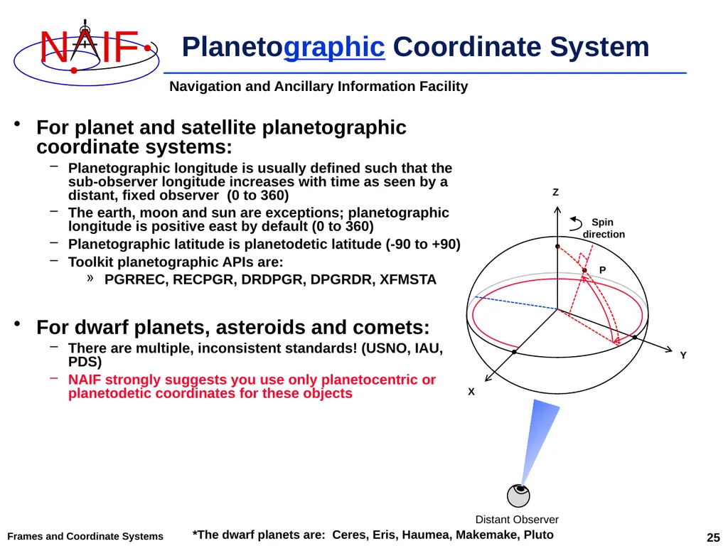
Frames and Coordinate Systems Planetographic Coordinate System For planet and satellite planetographic coordinate systems:
Planetographic longitude is usually defined such that the sub-observer longitude increases with time as seen by a distant, fixed observer (0 to 360)
The earth, moon and sun are exceptions; planetographic longitude is positive east by default (0 to 360)
Planetographic latitude is planetodetic latitude (-90 to +90)
Toolkit planetographic APIs are:
PGRREC, RECPGR, DRDPGR, DPGRDR, XFMSTA
For dwarf planets, asteroids and comets:
There are multiple, inconsistent standards! (USNO, IAU, PDS)
NAIF strongly suggests you use only planetocentric or planetodetic coordinates for these objects X Y Z Spin
direction P *The dwarf planets are: Ceres, Eris, Haumea, Makemake, Pluto 25 Distant Observer<br>
Planetographic longitude is usually defined such that the sub-observer longitude increases with time as seen by a distant, fixed observer (0 to 360)
The earth, moon and sun are exceptions; planetographic longitude is positive east by default (0 to 360)
Planetographic latitude is planetodetic latitude (-90 to +90)
Toolkit planetographic APIs are:
PGRREC, RECPGR, DRDPGR, DPGRDR, XFMSTA
For dwarf planets, asteroids and comets:
There are multiple, inconsistent standards! (USNO, IAU, PDS)
NAIF strongly suggests you use only planetocentric or planetodetic coordinates for these objects X Y Z Spin
direction P *The dwarf planets are: Ceres, Eris, Haumea, Makemake, Pluto 25 Distant Observer<br>
26
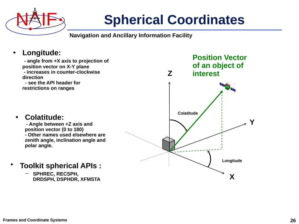
Spherical Coordinates Toolkit spherical APIs :
SPHREC, RECSPH, DRDSPH, DSPHDR, XFMSTA Frames and Coordinate Systems X Z Y Longitude:
- angle from +X axis to projection of position vector on X-Y plane
- increases in counter-clockwise direction
- see the API header for
restrictions on ranges Colatitude:
- Angle between +Z axis and position vector (0 to 180)
- Other names used elsewhere are zenith angle, inclination angle and polar angle. Position Vector
of an object of interest Longitude Colatitude 26<br>
SPHREC, RECSPH, DRDSPH, DSPHDR, XFMSTA Frames and Coordinate Systems X Z Y Longitude:
- angle from +X axis to projection of position vector on X-Y plane
- increases in counter-clockwise direction
- see the API header for
restrictions on ranges Colatitude:
- Angle between +Z axis and position vector (0 to 180)
- Other names used elsewhere are zenith angle, inclination angle and polar angle. Position Vector
of an object of interest Longitude Colatitude 26<br>
27
An Example of
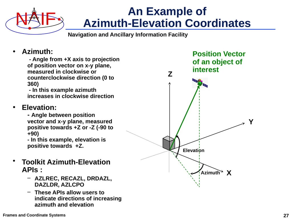
Azimuth-Elevation Coordinates Frames and Coordinate Systems X Z Y Azimuth:
- Angle from +X axis to projection of position vector on x-y plane, measured in clockwise or counterclockwise direction (0 to 360)
- In this example azimuth increases in clockwise direction Elevation:
- Angle between position
vector and x-y plane, measured positive towards +Z or -Z (-90 to +90)
- In this example, elevation is positive towards +Z. Position Vector
of an object of interest Elevation Azimuth 27 Toolkit Azimuth-Elevation APIs :
AZLREC, RECAZL, DRDAZL, DAZLDR, AZLCPO
These APIs allow users to indicate directions of increasing azimuth and elevation<br>
- Angle from +X axis to projection of position vector on x-y plane, measured in clockwise or counterclockwise direction (0 to 360)
- In this example azimuth increases in clockwise direction Elevation:
- Angle between position
vector and x-y plane, measured positive towards +Z or -Z (-90 to +90)
- In this example, elevation is positive towards +Z. Position Vector
of an object of interest Elevation Azimuth 27 Toolkit Azimuth-Elevation APIs :
AZLREC, RECAZL, DRDAZL, DAZLDR, AZLCPO
These APIs allow users to indicate directions of increasing azimuth and elevation<br>
28
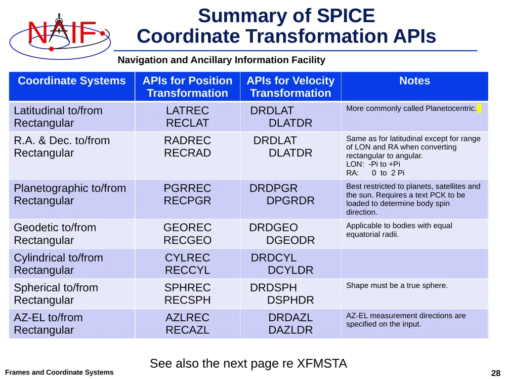
Summary of SPICE
Coordinate Transformation APIs 28 Frames and Coordinate Systems See also the next page re XFMSTA<br>
29
Frames and Coordinate Systems 29 Examples of Velocity
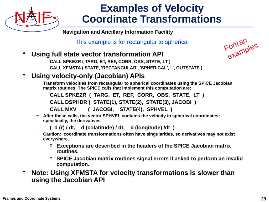
Coordinate Transformations Using full state vector transformation API
CALL SPKEZR ( TARG, ET, REF, CORR, OBS, STATE, LT )
CALL XFMSTA ( STATE, 'RECTANGULAR', 'SPHERICAL', ' ', OUTSTATE )
Using velocity-only (Jacobian) APIs
Transform velocities from rectangular to spherical coordinates using the SPICE Jacobian matrix routines. The SPICE calls that implement this computation are:
CALL SPKEZR ( TARG, ET, REF, CORR, OBS, STATE, LT )
CALL DSPHDR ( STATE(1), STATE(2), STATE(3), JACOBI )
CALL MXV ( JACOBI, STATE(4), SPHVEL )
After these calls, the vector SPHVEL contains the velocity in spherical coordinates: specifically, the derivatives
( d (r) / dt, d (colatitude) / dt, d (longitude) /dt )
Caution: coordinate transformations often have singularities, so derivatives may not exist everywhere.
Exceptions are described in the headers of the SPICE Jacobian matrix routines.
SPICE Jacobian matrix routines signal errors if asked to perform an invalid computation.
Note: Using XFMSTA for velocity transformations is slower than using the Jacobian API This example is for rectangular to spherical Fortran
examples<br>
CALL SPKEZR ( TARG, ET, REF, CORR, OBS, STATE, LT )
CALL XFMSTA ( STATE, 'RECTANGULAR', 'SPHERICAL', ' ', OUTSTATE )
Using velocity-only (Jacobian) APIs
Transform velocities from rectangular to spherical coordinates using the SPICE Jacobian matrix routines. The SPICE calls that implement this computation are:
CALL SPKEZR ( TARG, ET, REF, CORR, OBS, STATE, LT )
CALL DSPHDR ( STATE(1), STATE(2), STATE(3), JACOBI )
CALL MXV ( JACOBI, STATE(4), SPHVEL )
After these calls, the vector SPHVEL contains the velocity in spherical coordinates: specifically, the derivatives
( d (r) / dt, d (colatitude) / dt, d (longitude) /dt )
Caution: coordinate transformations often have singularities, so derivatives may not exist everywhere.
Exceptions are described in the headers of the SPICE Jacobian matrix routines.
SPICE Jacobian matrix routines signal errors if asked to perform an invalid computation.
Note: Using XFMSTA for velocity transformations is slower than using the Jacobian API This example is for rectangular to spherical Fortran
examples<br>