
Dynamic Reference Frames April 2023 Dynamic Frames
KL
Published · 61 slides · 0 views
1 / 1


Description
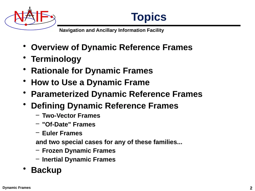
Dynamic Reference Frames April 2023 Dynamic Frames 2 Overview of Dynamic Reference Frames Terminology Rationale for Dynamic Frames How to Use a Dynamic Frame Parameterized Dynamic Reference Frames Defining Dynamic Reference Frames
Related Topics
Share
Embed code
Download this presentation From Below
"Dynamic Reference Frames April 2023 Dynamic Frames" is the property of its rightful owner. Permission is granted to download and print the materials on this website for personal, non-commercial use only, and to display it on your personal computer provided you do not modify the materials and that you retain all copyright notices contained in the materials. By downloading content from our website, you accept the terms of this agreement.
Presentation Transcript
01
Dynamic Reference Frames April 2023<br>
02
Dynamic Frames 2 Overview of Dynamic Reference Frames
Terminology
Rationale for Dynamic Frames
How to Use a Dynamic Frame
Parameterized Dynamic Reference Frames
Defining Dynamic Reference Frames
Two-Vector Frames
"Of-Date" Frames
Euler Frames
and two special cases for any of these families...
Frozen Dynamic Frames
Inertial Dynamic Frames
Backup Topics<br>
Terminology
Rationale for Dynamic Frames
How to Use a Dynamic Frame
Parameterized Dynamic Reference Frames
Defining Dynamic Reference Frames
Two-Vector Frames
"Of-Date" Frames
Euler Frames
and two special cases for any of these families...
Frozen Dynamic Frames
Inertial Dynamic Frames
Backup Topics<br>
03
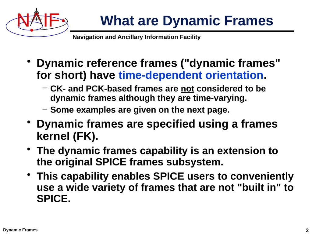
Dynamic Frames 3 Dynamic reference frames ("dynamic frames" for short) have time-dependent orientation.
CK- and PCK-based frames are not considered to be dynamic frames although they are time-varying.
Some examples are given on the next page.
Dynamic frames are specified using a frames kernel (FK).
The dynamic frames capability is an extension to the original SPICE frames subsystem.
This capability enables SPICE users to conveniently use a wide variety of frames that are not "built in" to SPICE. What are Dynamic Frames<br>
CK- and PCK-based frames are not considered to be dynamic frames although they are time-varying.
Some examples are given on the next page.
Dynamic frames are specified using a frames kernel (FK).
The dynamic frames capability is an extension to the original SPICE frames subsystem.
This capability enables SPICE users to conveniently use a wide variety of frames that are not "built in" to SPICE. What are Dynamic Frames<br>
04
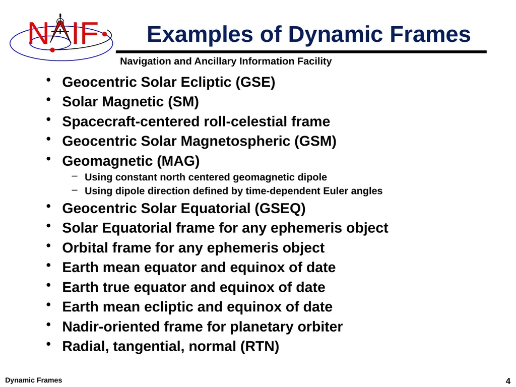
Dynamic Frames 4 Geocentric Solar Ecliptic (GSE)
Solar Magnetic (SM)
Spacecraft-centered roll-celestial frame
Geocentric Solar Magnetospheric (GSM)
Geomagnetic (MAG)
Using constant north centered geomagnetic dipole
Using dipole direction defined by time-dependent Euler angles
Geocentric Solar Equatorial (GSEQ)
Solar Equatorial frame for any ephemeris object
Orbital frame for any ephemeris object
Earth mean equator and equinox of date
Earth true equator and equinox of date
Earth mean ecliptic and equinox of date
Nadir-oriented frame for planetary orbiter
Radial, tangential, normal (RTN) Examples of Dynamic Frames<br>
Solar Magnetic (SM)
Spacecraft-centered roll-celestial frame
Geocentric Solar Magnetospheric (GSM)
Geomagnetic (MAG)
Using constant north centered geomagnetic dipole
Using dipole direction defined by time-dependent Euler angles
Geocentric Solar Equatorial (GSEQ)
Solar Equatorial frame for any ephemeris object
Orbital frame for any ephemeris object
Earth mean equator and equinox of date
Earth true equator and equinox of date
Earth mean ecliptic and equinox of date
Nadir-oriented frame for planetary orbiter
Radial, tangential, normal (RTN) Examples of Dynamic Frames<br>
05
Dynamic Frames 5 Why should SPICE offer dynamic frames implemented using a frames kernel? Instead…
a user could build a C-kernel for any frame.
SPICE could provide a limited number of "built-in" dynamic frames which wouldn't require a frames kernel.
users can create their own routines to implement dynamic frames.
Benefits of using a SPICE FK for this purpose
Convenience: using a formula rather than a C-kernel avoids C-kernel creation, dissemination, storage, and consistency issues.
Flexibility: the dynamic frame mechanism enables creation of a vast variety of reference frames.
Integration: once defined, and once supporting kernels are loaded, dynamic frames may be referenced in SPICE API calls.
Correct implementation: extensive testing done by NAIF, and perhaps further verified by a user, seems less likely to result in an error. Rationale<br>
a user could build a C-kernel for any frame.
SPICE could provide a limited number of "built-in" dynamic frames which wouldn't require a frames kernel.
users can create their own routines to implement dynamic frames.
Benefits of using a SPICE FK for this purpose
Convenience: using a formula rather than a C-kernel avoids C-kernel creation, dissemination, storage, and consistency issues.
Flexibility: the dynamic frame mechanism enables creation of a vast variety of reference frames.
Integration: once defined, and once supporting kernels are loaded, dynamic frames may be referenced in SPICE API calls.
Correct implementation: extensive testing done by NAIF, and perhaps further verified by a user, seems less likely to result in an error. Rationale<br>
06
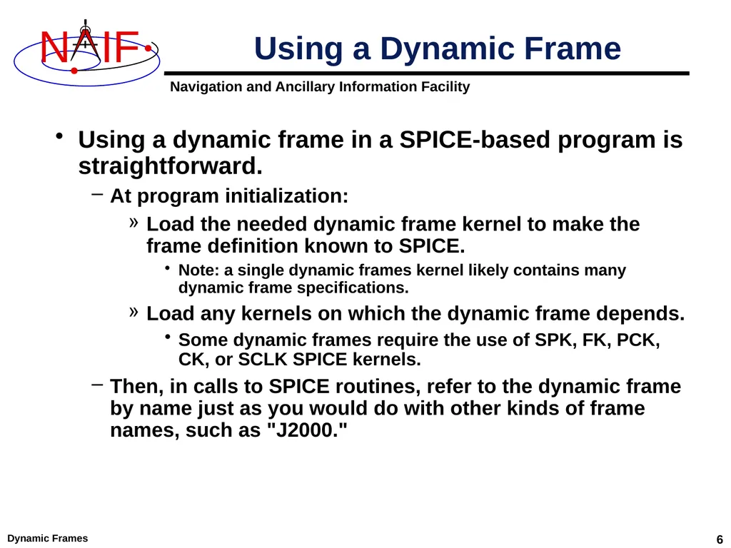
Dynamic Frames 6 Using a dynamic frame in a SPICE-based program is straightforward.
At program initialization:
Load the needed dynamic frame kernel to make the frame definition known to SPICE.
Note: a single dynamic frames kernel likely contains many dynamic frame specifications.
Load any kernels on which the dynamic frame depends.
Some dynamic frames require the use of SPK, FK, PCK, CK, or SCLK SPICE kernels.
Then, in calls to SPICE routines, refer to the dynamic frame by name just as you would do with other kinds of frame names, such as "J2000." Using a Dynamic Frame<br>
At program initialization:
Load the needed dynamic frame kernel to make the frame definition known to SPICE.
Note: a single dynamic frames kernel likely contains many dynamic frame specifications.
Load any kernels on which the dynamic frame depends.
Some dynamic frames require the use of SPK, FK, PCK, CK, or SCLK SPICE kernels.
Then, in calls to SPICE routines, refer to the dynamic frame by name just as you would do with other kinds of frame names, such as "J2000." Using a Dynamic Frame<br>
07
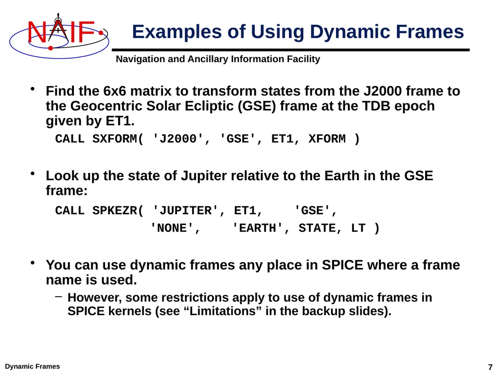
Dynamic Frames 7 Find the 6x6 matrix to transform states from the J2000 frame to the Geocentric Solar Ecliptic (GSE) frame at the TDB epoch given by ET1.
CALL SXFORM( 'J2000', 'GSE', ET1, XFORM )
Look up the state of Jupiter relative to the Earth in the GSE frame:
CALL SPKEZR( 'JUPITER', ET1, 'GSE',
'NONE', 'EARTH', STATE, LT )
You can use dynamic frames any place in SPICE where a frame name is used.
However, some restrictions apply to use of dynamic frames in SPICE kernels (see “Limitations” in the backup slides). Examples of Using Dynamic Frames<br>
CALL SXFORM( 'J2000', 'GSE', ET1, XFORM )
Look up the state of Jupiter relative to the Earth in the GSE frame:
CALL SPKEZR( 'JUPITER', ET1, 'GSE',
'NONE', 'EARTH', STATE, LT )
You can use dynamic frames any place in SPICE where a frame name is used.
However, some restrictions apply to use of dynamic frames in SPICE kernels (see “Limitations” in the backup slides). Examples of Using Dynamic Frames<br>
08
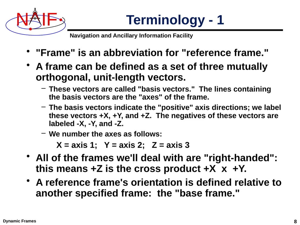
Dynamic Frames 8 "Frame" is an abbreviation for "reference frame."
A frame can be defined as a set of three mutually orthogonal, unit-length vectors.
These vectors are called "basis vectors." The lines containing the basis vectors are the "axes" of the frame.
The basis vectors indicate the "positive" axis directions; we label these vectors +X, +Y, and +Z. The negatives of these vectors are labeled -X, -Y, and -Z.
We number the axes as follows:
X = axis 1; Y = axis 2; Z = axis 3
All of the frames we'll deal with are "right-handed": this means +Z is the cross product +X x +Y.
A reference frame's orientation is defined relative to another specified frame: the "base frame." Terminology - 1<br>
A frame can be defined as a set of three mutually orthogonal, unit-length vectors.
These vectors are called "basis vectors." The lines containing the basis vectors are the "axes" of the frame.
The basis vectors indicate the "positive" axis directions; we label these vectors +X, +Y, and +Z. The negatives of these vectors are labeled -X, -Y, and -Z.
We number the axes as follows:
X = axis 1; Y = axis 2; Z = axis 3
All of the frames we'll deal with are "right-handed": this means +Z is the cross product +X x +Y.
A reference frame's orientation is defined relative to another specified frame: the "base frame." Terminology - 1<br>
09
Dynamic Frames 9 When we say that a frame is "time-dependent" or "time-varying," we mean:
The orientation of the frame is time-dependent.
Equivalently, the rotation between the frame and its base frame is time-dependent.
By "evaluating" a frame or "evaluating the orientation of a frame," we mean computing the rotation between the frame and its base frame.
Because of their time-dependent nature, an epoch is required in order to evaluate a dynamic frame.
In the SPICE system, frames are considered to have "centers."
The center of a frame is always an ephemeris object, something whose location can be specified with an SPK file.
Frame centers come into play when light time corrections are used: the apparent orientation of a time-dependent frame as seen by an observer is affected by the one-way light time between the frame's center and the observer. Terminology - 2<br>
The orientation of the frame is time-dependent.
Equivalently, the rotation between the frame and its base frame is time-dependent.
By "evaluating" a frame or "evaluating the orientation of a frame," we mean computing the rotation between the frame and its base frame.
Because of their time-dependent nature, an epoch is required in order to evaluate a dynamic frame.
In the SPICE system, frames are considered to have "centers."
The center of a frame is always an ephemeris object, something whose location can be specified with an SPK file.
Frame centers come into play when light time corrections are used: the apparent orientation of a time-dependent frame as seen by an observer is affected by the one-way light time between the frame's center and the observer. Terminology - 2<br>
10
Dynamic Frames 10 When we say that a vector is "aligned" with another vector, we mean that the angular separation between the two vectors is zero.
We use the terms "defining a frame" and "specifying a frame" interchangeably. Both refer to creating a frame definition in a frames kernel (FK).
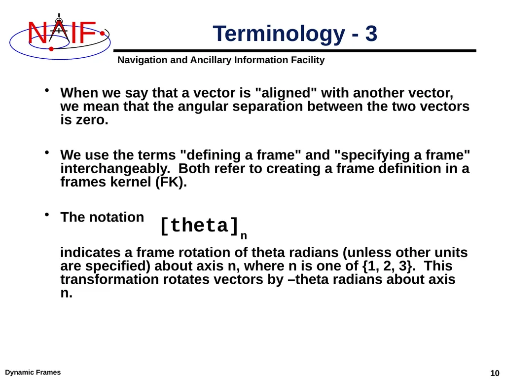
The notation
indicates a frame rotation of theta radians (unless other units are specified) about axis n, where n is one of {1, 2, 3}. This transformation rotates vectors by –theta radians about axis n. Terminology - 3 [theta]n<br>
We use the terms "defining a frame" and "specifying a frame" interchangeably. Both refer to creating a frame definition in a frames kernel (FK).
The notation
indicates a frame rotation of theta radians (unless other units are specified) about axis n, where n is one of {1, 2, 3}. This transformation rotates vectors by –theta radians about axis n. Terminology - 3 [theta]n<br>
11
Dynamic Frames 11 To define dynamic frames using a frames kernel, a fairly detailed understanding of the SPICE dynamic frames capability is required.
A good understanding of the basic SPICE system (in particular, the SPK and frames subsystems) is also a prerequisite.
See the Frames Required Reading document for the most detailed documentation available.
The rest of this tutorial is concerned with:
explaining the SPICE dynamic frames capability
showing how to create dynamic frames kernels
We present many dynamic frame definition examples Creating a Frames Kernel Defining Dynamic Frames<br>
A good understanding of the basic SPICE system (in particular, the SPK and frames subsystems) is also a prerequisite.
See the Frames Required Reading document for the most detailed documentation available.
The rest of this tutorial is concerned with:
explaining the SPICE dynamic frames capability
showing how to create dynamic frames kernels
We present many dynamic frame definition examples Creating a Frames Kernel Defining Dynamic Frames<br>
12
Types of Dynamic Frames NAIF envisages providing two types of dynamic frames:
parameterized
scripted
As of now only the parametrized type is implemented within SPICE; the rest of this tutorial focuses on this type. Dynamic Frames 12<br>
parameterized
scripted
As of now only the parametrized type is implemented within SPICE; the rest of this tutorial focuses on this type. Dynamic Frames 12<br>
13
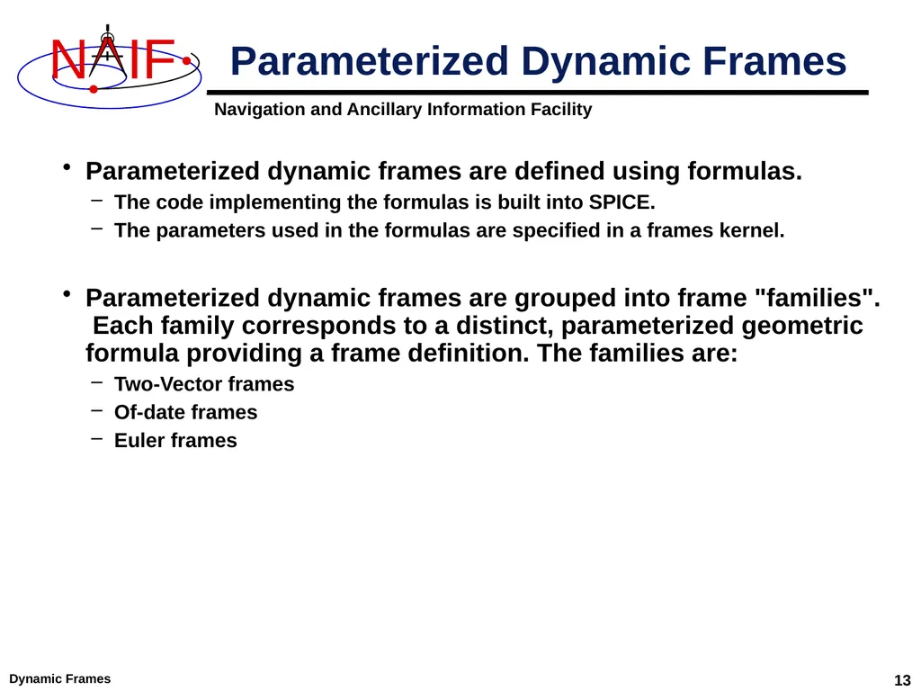
Dynamic Frames 13 Parameterized dynamic frames are defined using formulas.
The code implementing the formulas is built into SPICE.
The parameters used in the formulas are specified in a frames kernel.
Parameterized dynamic frames are grouped into frame "families". Each family corresponds to a distinct, parameterized geometric formula providing a frame definition. The families are:
Two-Vector frames
Of-date frames
Euler frames Parameterized Dynamic Frames<br>
The code implementing the formulas is built into SPICE.
The parameters used in the formulas are specified in a frames kernel.
Parameterized dynamic frames are grouped into frame "families". Each family corresponds to a distinct, parameterized geometric formula providing a frame definition. The families are:
Two-Vector frames
Of-date frames
Euler frames Parameterized Dynamic Frames<br>
14
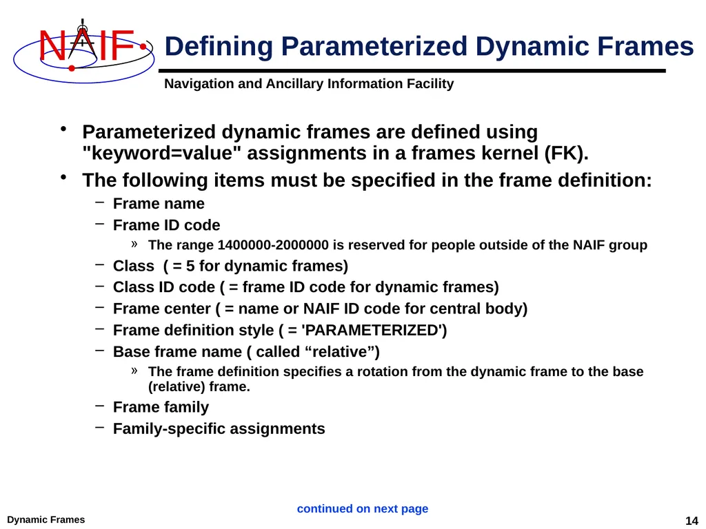
Dynamic Frames 14 Parameterized dynamic frames are defined using "keyword=value" assignments in a frames kernel (FK).
The following items must be specified in the frame definition:
Frame name
Frame ID code
The range 1400000-2000000 is reserved for people outside of the NAIF group
Class ( = 5 for dynamic frames)
Class ID code ( = frame ID code for dynamic frames)
Frame center ( = name or NAIF ID code for central body)
Frame definition style ( = 'PARAMETERIZED')
Base frame name ( called “relative”)
The frame definition specifies a rotation from the dynamic frame to the base (relative) frame.
Frame family
Family-specific assignments Defining Parameterized Dynamic Frames continued on next page<br>
The following items must be specified in the frame definition:
Frame name
Frame ID code
The range 1400000-2000000 is reserved for people outside of the NAIF group
Class ( = 5 for dynamic frames)
Class ID code ( = frame ID code for dynamic frames)
Frame center ( = name or NAIF ID code for central body)
Frame definition style ( = 'PARAMETERIZED')
Base frame name ( called “relative”)
The frame definition specifies a rotation from the dynamic frame to the base (relative) frame.
Frame family
Family-specific assignments Defining Parameterized Dynamic Frames continued on next page<br>
15
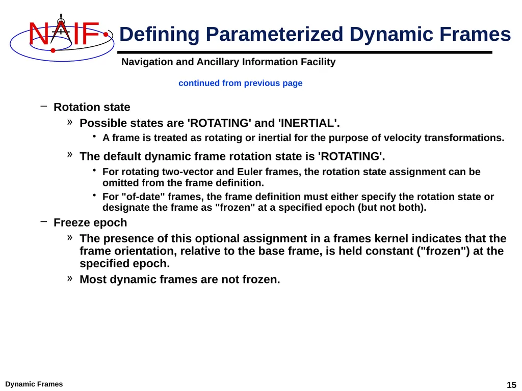
Dynamic Frames 15 Rotation state
Possible states are 'ROTATING' and 'INERTIAL'.
A frame is treated as rotating or inertial for the purpose of velocity transformations.
The default dynamic frame rotation state is 'ROTATING'.
For rotating two-vector and Euler frames, the rotation state assignment can be omitted from the frame definition.
For "of-date" frames, the frame definition must either specify the rotation state or designate the frame as "frozen" at a specified epoch (but not both).
Freeze epoch
The presence of this optional assignment in a frames kernel indicates that the frame orientation, relative to the base frame, is held constant ("frozen") at the specified epoch.
Most dynamic frames are not frozen. Defining Parameterized Dynamic Frames continued from previous page<br>
Possible states are 'ROTATING' and 'INERTIAL'.
A frame is treated as rotating or inertial for the purpose of velocity transformations.
The default dynamic frame rotation state is 'ROTATING'.
For rotating two-vector and Euler frames, the rotation state assignment can be omitted from the frame definition.
For "of-date" frames, the frame definition must either specify the rotation state or designate the frame as "frozen" at a specified epoch (but not both).
Freeze epoch
The presence of this optional assignment in a frames kernel indicates that the frame orientation, relative to the base frame, is held constant ("frozen") at the specified epoch.
Most dynamic frames are not frozen. Defining Parameterized Dynamic Frames continued from previous page<br>
16
What’s Next? In the next approximately 35 pages we’ll provide implementation details and examples of frames belonging to each of the parameterized dynamic frame families:
Two-Vector frames
"Of-Date" frames
Euler frames
Product frames
We’ll also explain the optional frame attributes which can be assigned to frames belonging to the above families:
“Frozen”
“Inertial” Dynamic Frames 16<br>
Two-Vector frames
"Of-Date" frames
Euler frames
Product frames
We’ll also explain the optional frame attributes which can be assigned to frames belonging to the above families:
“Frozen”
“Inertial” Dynamic Frames 16<br>
17
Dynamic Frames 17 Two-vector frames are defined using two time-dependent vectors: the "primary" and "secondary" vectors.
Each vector may be defined by a variety of geometric means:
Position vector
Target near point vector
Velocity vector
Constant vector
The user associates specified positive or negative axes of the two-vector frame with the primary and secondary vectors.
Two-vector frames are always right-handed and have orthogonal axes, so two non-parallel vectors and associations of axes with these vectors suffice to define the orientation of a frame. Two-Vector Frame Concepts - 1<br>
Each vector may be defined by a variety of geometric means:
Position vector
Target near point vector
Velocity vector
Constant vector
The user associates specified positive or negative axes of the two-vector frame with the primary and secondary vectors.
Two-vector frames are always right-handed and have orthogonal axes, so two non-parallel vectors and associations of axes with these vectors suffice to define the orientation of a frame. Two-Vector Frame Concepts - 1<br>
18
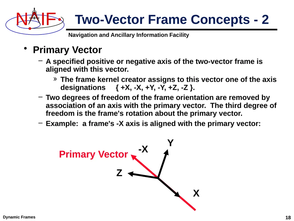
Dynamic Frames 18 Primary Vector
A specified positive or negative axis of the two-vector frame is aligned with this vector.
The frame kernel creator assigns to this vector one of the axis designations { +X, -X, +Y, -Y, +Z, -Z }.
Two degrees of freedom of the frame orientation are removed by association of an axis with the primary vector. The third degree of freedom is the frame's rotation about the primary vector.
Example: a frame's -X axis is aligned with the primary vector: Two-Vector Frame Concepts - 2<br>
A specified positive or negative axis of the two-vector frame is aligned with this vector.
The frame kernel creator assigns to this vector one of the axis designations { +X, -X, +Y, -Y, +Z, -Z }.
Two degrees of freedom of the frame orientation are removed by association of an axis with the primary vector. The third degree of freedom is the frame's rotation about the primary vector.
Example: a frame's -X axis is aligned with the primary vector: Two-Vector Frame Concepts - 2<br>
19
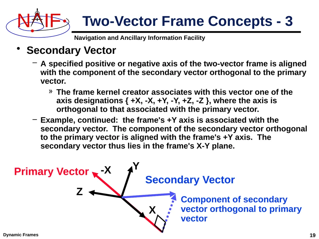
Dynamic Frames 19 Secondary Vector
A specified positive or negative axis of the two-vector frame is aligned with the component of the secondary vector orthogonal to the primary vector.
The frame kernel creator associates with this vector one of the axis designations { +X, -X, +Y, -Y, +Z, -Z }, where the axis is orthogonal to that associated with the primary vector.
Example, continued: the frame's +Y axis is associated with the secondary vector. The component of the secondary vector orthogonal to the primary vector is aligned with the frame's +Y axis. The secondary vector thus lies in the frame's X-Y plane. Two-Vector Frame Concepts - 3 X Y Z Primary Vector Secondary Vector -X Component of secondary vector orthogonal to primary vector<br>
A specified positive or negative axis of the two-vector frame is aligned with the component of the secondary vector orthogonal to the primary vector.
The frame kernel creator associates with this vector one of the axis designations { +X, -X, +Y, -Y, +Z, -Z }, where the axis is orthogonal to that associated with the primary vector.
Example, continued: the frame's +Y axis is associated with the secondary vector. The component of the secondary vector orthogonal to the primary vector is aligned with the frame's +Y axis. The secondary vector thus lies in the frame's X-Y plane. Two-Vector Frame Concepts - 3 X Y Z Primary Vector Secondary Vector -X Component of secondary vector orthogonal to primary vector<br>
20
Dynamic Frames 20 Secondary Vector, continued
Typically the secondary vector itself is not orthogonal to the primary vector.
However, the secondary vector must be linearly independent of the primary vector.
Near-degenerate geometry can lead to extreme loss of precision.
This problem can be difficult to diagnose.
SPICE enforces independence using a default angular separation tolerance of 1 milliradian. The angular separation of the primary and secondary vectors may not differ from 0 or Pi radians by less than this tolerance.
A frame kernel creator can specify a different tolerance value. The frame kernel assignment for this is:
FRAME_<frame_ID>_ANGLE_SEP_TOL = <tolerance>
where the tolerance is given in radians.
Designers of two-vector frames should ensure that the primary and secondary vectors can't become nearly parallel for any realistic evaluation epoch. Two-Vector Frame Concepts - 4<br>
Typically the secondary vector itself is not orthogonal to the primary vector.
However, the secondary vector must be linearly independent of the primary vector.
Near-degenerate geometry can lead to extreme loss of precision.
This problem can be difficult to diagnose.
SPICE enforces independence using a default angular separation tolerance of 1 milliradian. The angular separation of the primary and secondary vectors may not differ from 0 or Pi radians by less than this tolerance.
A frame kernel creator can specify a different tolerance value. The frame kernel assignment for this is:
FRAME_<frame_ID>_ANGLE_SEP_TOL = <tolerance>
where the tolerance is given in radians.
Designers of two-vector frames should ensure that the primary and secondary vectors can't become nearly parallel for any realistic evaluation epoch. Two-Vector Frame Concepts - 4<br>
21
Two-Vector Frame Concepts - 5 In the next several pages we’ll describe methods for specifying the primary and secondary vectors used in creating a dynamic frame. Dynamic Frames 21<br>
22
Dynamic Frames 22 Using a Position Vector
Defined by the position of one ephemeris object relative to another. The frame kernel creator specifies:
the target
the observer
the aberration correction
The vector may optionally be corrected for light time and stellar aberration.
The epoch at which the position vector is computed is supplied via a call to a SPICE API:
as an input to an SPK routine, e.g. SPKEZR, SPKPOS.
as an input to a frame system routine, e.g. SXFORM, PXFORM.
The reference frame relative to which the vector is expressed is not specified by the frame kernel creator.
SPICE automatically selects this frame. Two-Vector Frame Concepts - 6<br>
Defined by the position of one ephemeris object relative to another. The frame kernel creator specifies:
the target
the observer
the aberration correction
The vector may optionally be corrected for light time and stellar aberration.
The epoch at which the position vector is computed is supplied via a call to a SPICE API:
as an input to an SPK routine, e.g. SPKEZR, SPKPOS.
as an input to a frame system routine, e.g. SXFORM, PXFORM.
The reference frame relative to which the vector is expressed is not specified by the frame kernel creator.
SPICE automatically selects this frame. Two-Vector Frame Concepts - 6<br>
23
Dynamic Frames 23 Using a Target Near Point Vector
Defined as the vector from an observer to the nearest point on a specified extended target body to that observer. The frame kernel creator specifies:
the target
the observer
the aberration correction
The vector may optionally be corrected for one-way light time and stellar aberration.
When one-way light time correction is used, both the position and orientation of the target body are corrected for light time.
The extended target body is modeled as a triaxial ellipsoid.
Size and shape data are given by a PCK.
The epoch is supplied via a SPICE API call.
The reference frame relative to which the vector is expressed is not specified by the frame kernel creator.
SPICE automatically selects this frame. Two-Vector Frame Concepts - 7<br>
Defined as the vector from an observer to the nearest point on a specified extended target body to that observer. The frame kernel creator specifies:
the target
the observer
the aberration correction
The vector may optionally be corrected for one-way light time and stellar aberration.
When one-way light time correction is used, both the position and orientation of the target body are corrected for light time.
The extended target body is modeled as a triaxial ellipsoid.
Size and shape data are given by a PCK.
The epoch is supplied via a SPICE API call.
The reference frame relative to which the vector is expressed is not specified by the frame kernel creator.
SPICE automatically selects this frame. Two-Vector Frame Concepts - 7<br>
24
Dynamic Frames 24 Using a Velocity Vector
Defined by the velocity of a target ephemeris object relative to an observing ephemeris object. The frame kernel creator specifies:
the target
the observer
the velocity reference frame
This frame may be distinct from the base frame.
Different velocity frame choices can lead to radically different two-vector frame definitions.
the aberration correction
The velocity vector may optionally be corrected for one-way light time and stellar aberration.
Use of light time correction also implies evaluation of the velocity vector's frame at a light time corrected epoch: the epoch is corrected for light time between the velocity frame's center and the observer, if the velocity frame is non-inertial.
The epoch is supplied via a SPICE API call. Two-Vector Frame Concepts - 8<br>
Defined by the velocity of a target ephemeris object relative to an observing ephemeris object. The frame kernel creator specifies:
the target
the observer
the velocity reference frame
This frame may be distinct from the base frame.
Different velocity frame choices can lead to radically different two-vector frame definitions.
the aberration correction
The velocity vector may optionally be corrected for one-way light time and stellar aberration.
Use of light time correction also implies evaluation of the velocity vector's frame at a light time corrected epoch: the epoch is corrected for light time between the velocity frame's center and the observer, if the velocity frame is non-inertial.
The epoch is supplied via a SPICE API call. Two-Vector Frame Concepts - 8<br>
25
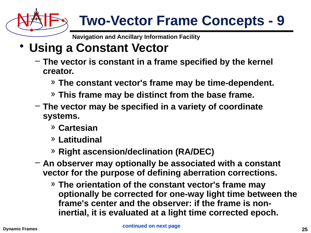
Dynamic Frames 25 Using a Constant Vector
The vector is constant in a frame specified by the kernel creator.
The constant vector's frame may be time-dependent.
This frame may be distinct from the base frame.
The vector may be specified in a variety of coordinate systems.
Cartesian
Latitudinal
Right ascension/declination (RA/DEC)
An observer may optionally be associated with a constant vector for the purpose of defining aberration corrections.
The orientation of the constant vector's frame may optionally be corrected for one-way light time between the frame's center and the observer: if the frame is non-inertial, it is evaluated at a light time corrected epoch. Two-Vector Frame Concepts - 9 continued on next page<br>
The vector is constant in a frame specified by the kernel creator.
The constant vector's frame may be time-dependent.
This frame may be distinct from the base frame.
The vector may be specified in a variety of coordinate systems.
Cartesian
Latitudinal
Right ascension/declination (RA/DEC)
An observer may optionally be associated with a constant vector for the purpose of defining aberration corrections.
The orientation of the constant vector's frame may optionally be corrected for one-way light time between the frame's center and the observer: if the frame is non-inertial, it is evaluated at a light time corrected epoch. Two-Vector Frame Concepts - 9 continued on next page<br>
26
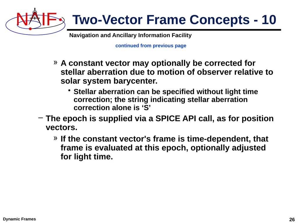
Dynamic Frames 26 A constant vector may optionally be corrected for stellar aberration due to motion of observer relative to solar system barycenter.
Stellar aberration can be specified without light time correction; the string indicating stellar aberration correction alone is ‘S’
The epoch is supplied via a SPICE API call, as for position vectors.
If the constant vector's frame is time-dependent, that frame is evaluated at this epoch, optionally adjusted for light time. Two-Vector Frame Concepts - 10 continued from previous page<br>
Stellar aberration can be specified without light time correction; the string indicating stellar aberration correction alone is ‘S’
The epoch is supplied via a SPICE API call, as for position vectors.
If the constant vector's frame is time-dependent, that frame is evaluated at this epoch, optionally adjusted for light time. Two-Vector Frame Concepts - 10 continued from previous page<br>
27
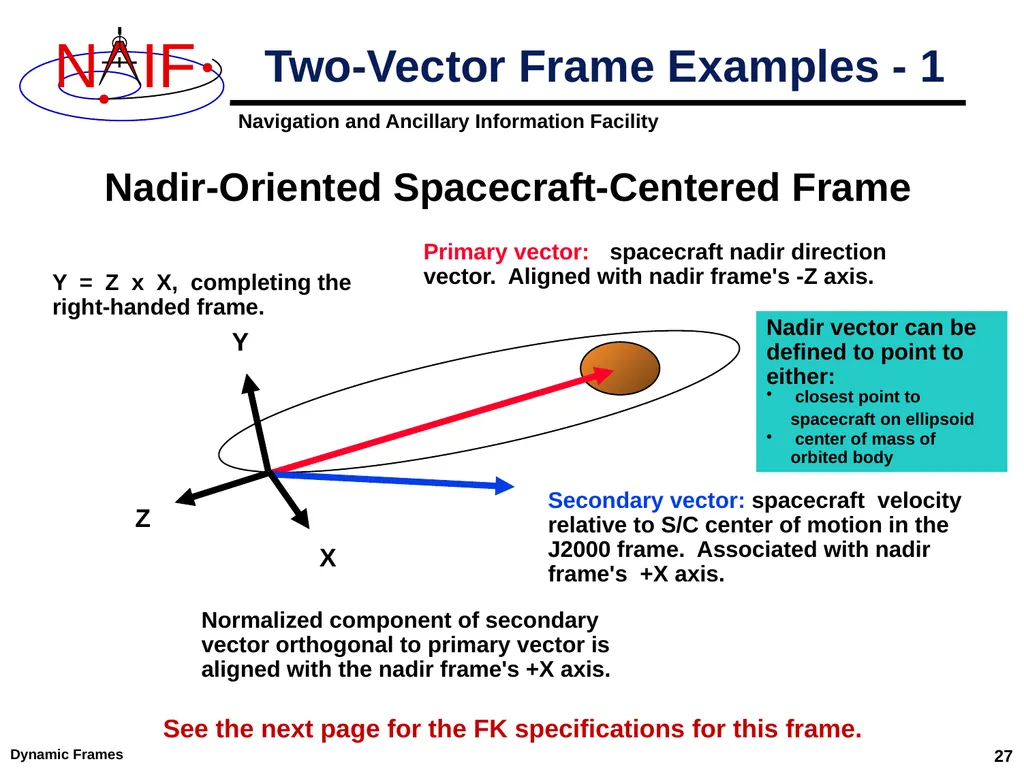
Dynamic Frames 27 Two-Vector Frame Examples - 1 Primary vector: spacecraft nadir direction vector. Aligned with nadir frame's -Z axis. Secondary vector: spacecraft velocity relative to S/C center of motion in the J2000 frame. Associated with nadir frame's +X axis. Normalized component of secondary
vector orthogonal to primary vector is aligned with the nadir frame's +X axis. X Y = Z x X, completing the
right-handed frame. Z Y Nadir-Oriented Spacecraft-Centered Frame Nadir vector can be defined to point to either:
closest point to spacecraft on ellipsoid
center of mass of orbited body See the next page for the FK specifications for this frame.<br>
vector orthogonal to primary vector is aligned with the nadir frame's +X axis. X Y = Z x X, completing the
right-handed frame. Z Y Nadir-Oriented Spacecraft-Centered Frame Nadir vector can be defined to point to either:
closest point to spacecraft on ellipsoid
center of mass of orbited body See the next page for the FK specifications for this frame.<br>
28
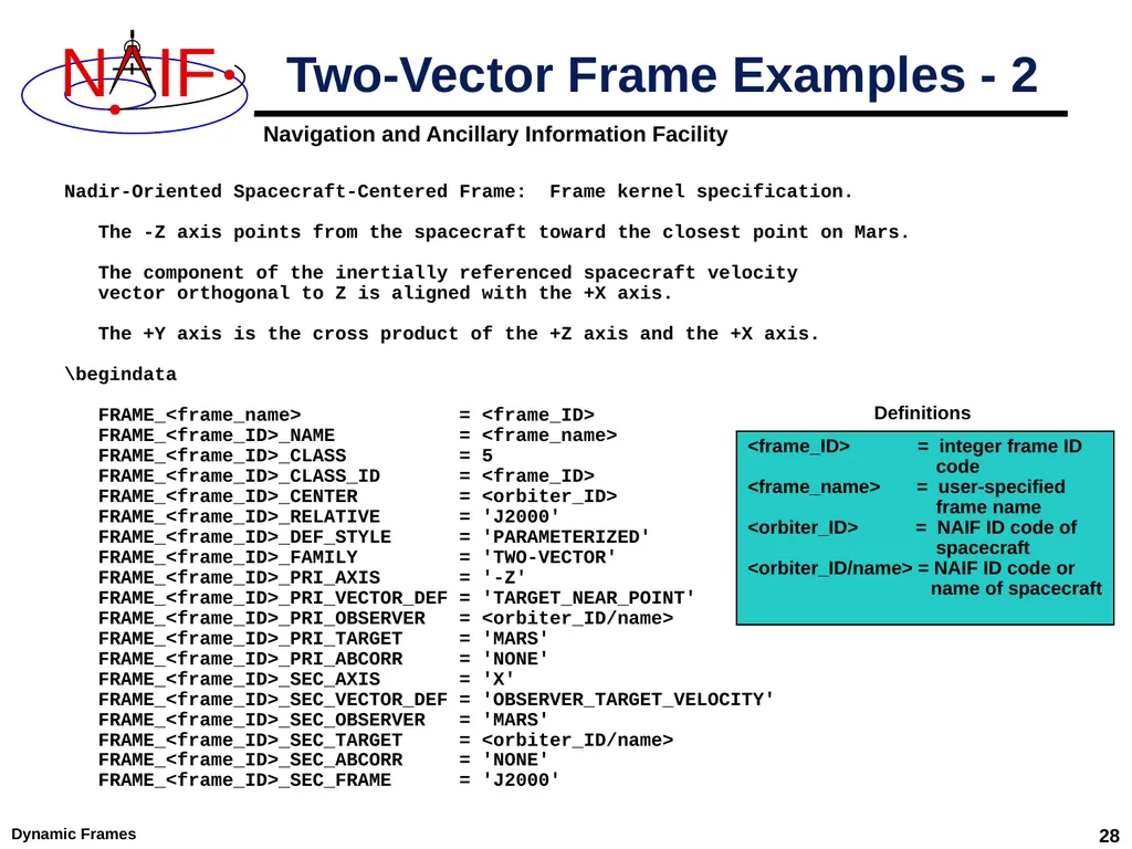
Dynamic Frames 28 Nadir-Oriented Spacecraft-Centered Frame: Frame kernel specification.
The -Z axis points from the spacecraft toward the closest point on Mars.
The component of the inertially referenced spacecraft velocity
vector orthogonal to Z is aligned with the +X axis.
The +Y axis is the cross product of the +Z axis and the +X axis.
\begindata
FRAME_<frame_name> = <frame_ID>
FRAME_<frame_ID>_NAME = <frame_name>
FRAME_<frame_ID>_CLASS = 5
FRAME_<frame_ID>_CLASS_ID = <frame_ID>
FRAME_<frame_ID>_CENTER = <orbiter_ID>
FRAME_<frame_ID>_RELATIVE = 'J2000'
FRAME_<frame_ID>_DEF_STYLE = 'PARAMETERIZED'
FRAME_<frame_ID>_FAMILY = 'TWO-VECTOR'
FRAME_<frame_ID>_PRI_AXIS = '-Z'
FRAME_<frame_ID>_PRI_VECTOR_DEF = 'TARGET_NEAR_POINT'
FRAME_<frame_ID>_PRI_OBSERVER = <orbiter_ID/name>
FRAME_<frame_ID>_PRI_TARGET = 'MARS'
FRAME_<frame_ID>_PRI_ABCORR = 'NONE'
FRAME_<frame_ID>_SEC_AXIS = 'X'
FRAME_<frame_ID>_SEC_VECTOR_DEF = 'OBSERVER_TARGET_VELOCITY'
FRAME_<frame_ID>_SEC_OBSERVER = 'MARS'
FRAME_<frame_ID>_SEC_TARGET = <orbiter_ID/name>
FRAME_<frame_ID>_SEC_ABCORR = 'NONE'
FRAME_<frame_ID>_SEC_FRAME = 'J2000' Two-Vector Frame Examples - 2 <frame_ID> = integer frame ID
code
<frame_name> = user-specified
frame name
<orbiter_ID> = NAIF ID code of
spacecraft
<orbiter_ID/name> = NAIF ID code or
name of spacecraft Definitions<br>
The -Z axis points from the spacecraft toward the closest point on Mars.
The component of the inertially referenced spacecraft velocity
vector orthogonal to Z is aligned with the +X axis.
The +Y axis is the cross product of the +Z axis and the +X axis.
\begindata
FRAME_<frame_name> = <frame_ID>
FRAME_<frame_ID>_NAME = <frame_name>
FRAME_<frame_ID>_CLASS = 5
FRAME_<frame_ID>_CLASS_ID = <frame_ID>
FRAME_<frame_ID>_CENTER = <orbiter_ID>
FRAME_<frame_ID>_RELATIVE = 'J2000'
FRAME_<frame_ID>_DEF_STYLE = 'PARAMETERIZED'
FRAME_<frame_ID>_FAMILY = 'TWO-VECTOR'
FRAME_<frame_ID>_PRI_AXIS = '-Z'
FRAME_<frame_ID>_PRI_VECTOR_DEF = 'TARGET_NEAR_POINT'
FRAME_<frame_ID>_PRI_OBSERVER = <orbiter_ID/name>
FRAME_<frame_ID>_PRI_TARGET = 'MARS'
FRAME_<frame_ID>_PRI_ABCORR = 'NONE'
FRAME_<frame_ID>_SEC_AXIS = 'X'
FRAME_<frame_ID>_SEC_VECTOR_DEF = 'OBSERVER_TARGET_VELOCITY'
FRAME_<frame_ID>_SEC_OBSERVER = 'MARS'
FRAME_<frame_ID>_SEC_TARGET = <orbiter_ID/name>
FRAME_<frame_ID>_SEC_ABCORR = 'NONE'
FRAME_<frame_ID>_SEC_FRAME = 'J2000' Two-Vector Frame Examples - 2 <frame_ID> = integer frame ID
code
<frame_name> = user-specified
frame name
<orbiter_ID> = NAIF ID code of
spacecraft
<orbiter_ID/name> = NAIF ID code or
name of spacecraft Definitions<br>
29
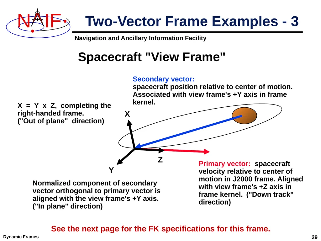
Dynamic Frames 29 Two-Vector Frame Examples - 3 Secondary vector:
spacecraft position relative to center of motion. Associated with view frame's +Y axis in frame kernel. Primary vector: spacecraft velocity relative to center of motion in J2000 frame. Aligned with view frame's +Z axis in frame kernel. ("Down track" direction) Spacecraft "View Frame" Normalized component of secondary
vector orthogonal to primary vector is aligned with the view frame's +Y axis. ("In plane" direction) Z X = Y x Z, completing the
right-handed frame.
("Out of plane" direction) Y X See the next page for the FK specifications for this frame.<br>
spacecraft position relative to center of motion. Associated with view frame's +Y axis in frame kernel. Primary vector: spacecraft velocity relative to center of motion in J2000 frame. Aligned with view frame's +Z axis in frame kernel. ("Down track" direction) Spacecraft "View Frame" Normalized component of secondary
vector orthogonal to primary vector is aligned with the view frame's +Y axis. ("In plane" direction) Z X = Y x Z, completing the
right-handed frame.
("Out of plane" direction) Y X See the next page for the FK specifications for this frame.<br>
30
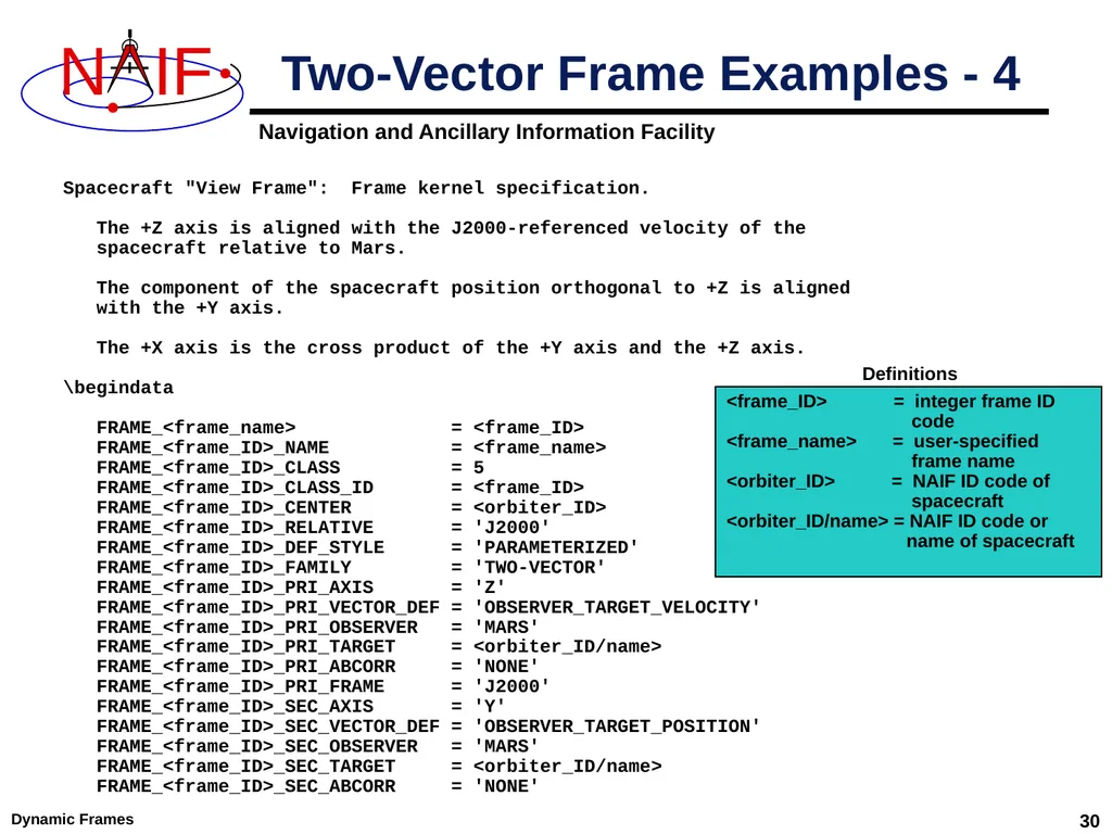
Dynamic Frames 30 Spacecraft "View Frame": Frame kernel specification.
The +Z axis is aligned with the J2000-referenced velocity of the
spacecraft relative to Mars.
The component of the spacecraft position orthogonal to +Z is aligned
with the +Y axis.
The +X axis is the cross product of the +Y axis and the +Z axis.
\begindata
FRAME_<frame_name> = <frame_ID>
FRAME_<frame_ID>_NAME = <frame_name>
FRAME_<frame_ID>_CLASS = 5
FRAME_<frame_ID>_CLASS_ID = <frame_ID>
FRAME_<frame_ID>_CENTER = <orbiter_ID>
FRAME_<frame_ID>_RELATIVE = 'J2000'
FRAME_<frame_ID>_DEF_STYLE = 'PARAMETERIZED'
FRAME_<frame_ID>_FAMILY = 'TWO-VECTOR'
FRAME_<frame_ID>_PRI_AXIS = 'Z'
FRAME_<frame_ID>_PRI_VECTOR_DEF = 'OBSERVER_TARGET_VELOCITY'
FRAME_<frame_ID>_PRI_OBSERVER = 'MARS'
FRAME_<frame_ID>_PRI_TARGET = <orbiter_ID/name>
FRAME_<frame_ID>_PRI_ABCORR = 'NONE'
FRAME_<frame_ID>_PRI_FRAME = 'J2000'
FRAME_<frame_ID>_SEC_AXIS = 'Y'
FRAME_<frame_ID>_SEC_VECTOR_DEF = 'OBSERVER_TARGET_POSITION'
FRAME_<frame_ID>_SEC_OBSERVER = 'MARS'
FRAME_<frame_ID>_SEC_TARGET = <orbiter_ID/name>
FRAME_<frame_ID>_SEC_ABCORR = 'NONE' Two-Vector Frame Examples - 4 <frame_ID> = integer frame ID
code
<frame_name> = user-specified
frame name
<orbiter_ID> = NAIF ID code of
spacecraft
<orbiter_ID/name> = NAIF ID code or
name of spacecraft Definitions<br>
The +Z axis is aligned with the J2000-referenced velocity of the
spacecraft relative to Mars.
The component of the spacecraft position orthogonal to +Z is aligned
with the +Y axis.
The +X axis is the cross product of the +Y axis and the +Z axis.
\begindata
FRAME_<frame_name> = <frame_ID>
FRAME_<frame_ID>_NAME = <frame_name>
FRAME_<frame_ID>_CLASS = 5
FRAME_<frame_ID>_CLASS_ID = <frame_ID>
FRAME_<frame_ID>_CENTER = <orbiter_ID>
FRAME_<frame_ID>_RELATIVE = 'J2000'
FRAME_<frame_ID>_DEF_STYLE = 'PARAMETERIZED'
FRAME_<frame_ID>_FAMILY = 'TWO-VECTOR'
FRAME_<frame_ID>_PRI_AXIS = 'Z'
FRAME_<frame_ID>_PRI_VECTOR_DEF = 'OBSERVER_TARGET_VELOCITY'
FRAME_<frame_ID>_PRI_OBSERVER = 'MARS'
FRAME_<frame_ID>_PRI_TARGET = <orbiter_ID/name>
FRAME_<frame_ID>_PRI_ABCORR = 'NONE'
FRAME_<frame_ID>_PRI_FRAME = 'J2000'
FRAME_<frame_ID>_SEC_AXIS = 'Y'
FRAME_<frame_ID>_SEC_VECTOR_DEF = 'OBSERVER_TARGET_POSITION'
FRAME_<frame_ID>_SEC_OBSERVER = 'MARS'
FRAME_<frame_ID>_SEC_TARGET = <orbiter_ID/name>
FRAME_<frame_ID>_SEC_ABCORR = 'NONE' Two-Vector Frame Examples - 4 <frame_ID> = integer frame ID
code
<frame_name> = user-specified
frame name
<orbiter_ID> = NAIF ID code of
spacecraft
<orbiter_ID/name> = NAIF ID code or
name of spacecraft Definitions<br>
31
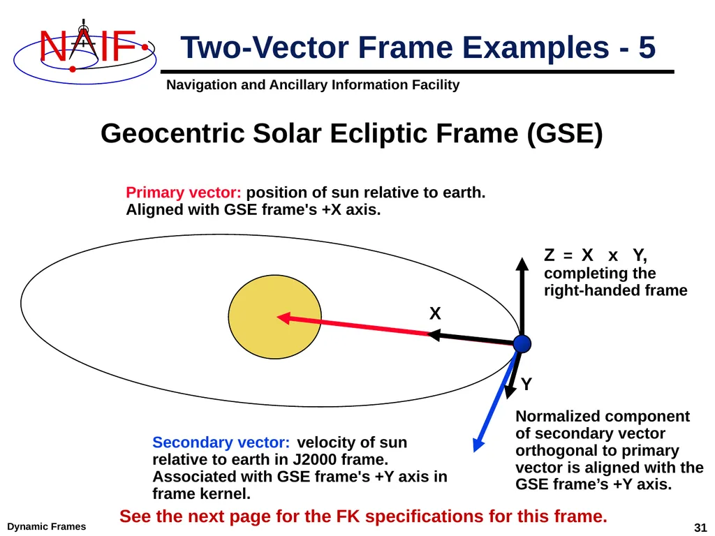
Dynamic Frames 31 Two-Vector Frame Examples - 5 Secondary vector: velocity of sun
relative to earth in J2000 frame.
Associated with GSE frame's +Y axis in frame kernel. Geocentric Solar Ecliptic Frame (GSE) X Z = X x Y,
completing the
right-handed frame Primary vector: position of sun relative to earth.
Aligned with GSE frame's +X axis. Y See the next page for the FK specifications for this frame. Normalized component of secondary vector orthogonal to primary vector is aligned with the GSE frame’s +Y axis.<br>
relative to earth in J2000 frame.
Associated with GSE frame's +Y axis in frame kernel. Geocentric Solar Ecliptic Frame (GSE) X Z = X x Y,
completing the
right-handed frame Primary vector: position of sun relative to earth.
Aligned with GSE frame's +X axis. Y See the next page for the FK specifications for this frame. Normalized component of secondary vector orthogonal to primary vector is aligned with the GSE frame’s +Y axis.<br>
32
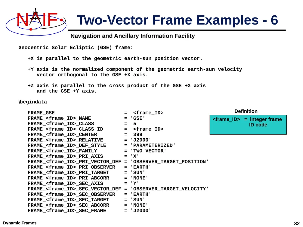
Dynamic Frames 32 Two-Vector Frame Examples - 6 Geocentric Solar Ecliptic (GSE) frame:
+X is parallel to the geometric earth-sun position vector.
+Y axis is the normalized component of the geometric earth-sun velocity
vector orthogonal to the GSE +X axis.
+Z axis is parallel to the cross product of the GSE +X axis
and the GSE +Y axis.
\begindata
FRAME_GSE = <frame_ID>
FRAME_<frame_ID>_NAME = 'GSE'
FRAME_<frame_ID>_CLASS = 5
FRAME_<frame_ID>_CLASS_ID = <frame_ID>
FRAME_<frame_ID>_CENTER = 399
FRAME_<frame_ID>_RELATIVE = 'J2000'
FRAME_<frame_ID>_DEF_STYLE = 'PARAMETERIZED'
FRAME_<frame_ID>_FAMILY = 'TWO-VECTOR'
FRAME_<frame_ID>_PRI_AXIS = 'X'
FRAME_<frame_ID>_PRI_VECTOR_DEF = 'OBSERVER_TARGET_POSITION'
FRAME_<frame_ID>_PRI_OBSERVER = 'EARTH'
FRAME_<frame_ID>_PRI_TARGET = 'SUN'
FRAME_<frame_ID>_PRI_ABCORR = 'NONE'
FRAME_<frame_ID>_SEC_AXIS = 'Y'
FRAME_<frame_ID>_SEC_VECTOR_DEF = 'OBSERVER_TARGET_VELOCITY'
FRAME_<frame_ID>_SEC_OBSERVER = 'EARTH'
FRAME_<frame_ID>_SEC_TARGET = 'SUN'
FRAME_<frame_ID>_SEC_ABCORR = 'NONE'
FRAME_<frame_ID>_SEC_FRAME = 'J2000' <frame_ID> = integer frame
ID code Definition<br>
+X is parallel to the geometric earth-sun position vector.
+Y axis is the normalized component of the geometric earth-sun velocity
vector orthogonal to the GSE +X axis.
+Z axis is parallel to the cross product of the GSE +X axis
and the GSE +Y axis.
\begindata
FRAME_GSE = <frame_ID>
FRAME_<frame_ID>_NAME = 'GSE'
FRAME_<frame_ID>_CLASS = 5
FRAME_<frame_ID>_CLASS_ID = <frame_ID>
FRAME_<frame_ID>_CENTER = 399
FRAME_<frame_ID>_RELATIVE = 'J2000'
FRAME_<frame_ID>_DEF_STYLE = 'PARAMETERIZED'
FRAME_<frame_ID>_FAMILY = 'TWO-VECTOR'
FRAME_<frame_ID>_PRI_AXIS = 'X'
FRAME_<frame_ID>_PRI_VECTOR_DEF = 'OBSERVER_TARGET_POSITION'
FRAME_<frame_ID>_PRI_OBSERVER = 'EARTH'
FRAME_<frame_ID>_PRI_TARGET = 'SUN'
FRAME_<frame_ID>_PRI_ABCORR = 'NONE'
FRAME_<frame_ID>_SEC_AXIS = 'Y'
FRAME_<frame_ID>_SEC_VECTOR_DEF = 'OBSERVER_TARGET_VELOCITY'
FRAME_<frame_ID>_SEC_OBSERVER = 'EARTH'
FRAME_<frame_ID>_SEC_TARGET = 'SUN'
FRAME_<frame_ID>_SEC_ABCORR = 'NONE'
FRAME_<frame_ID>_SEC_FRAME = 'J2000' <frame_ID> = integer frame
ID code Definition<br>
33
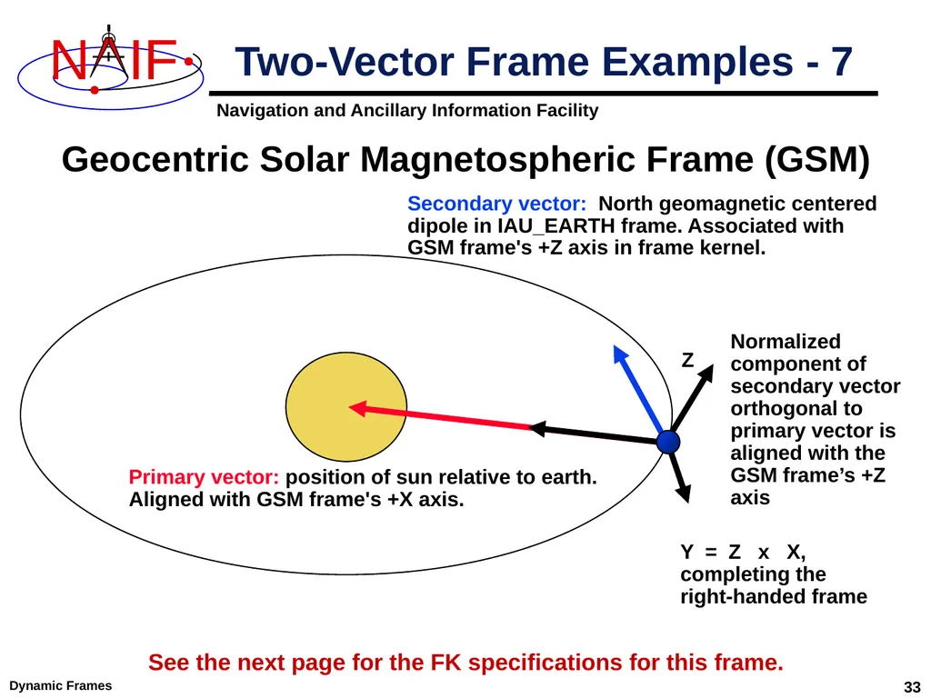
Dynamic Frames 33 Two-Vector Frame Examples - 7 Secondary vector: North geomagnetic centered
dipole in IAU_EARTH frame. Associated with
GSM frame's +Z axis in frame kernel. Normalized
component of
secondary vector
orthogonal to
primary vector is aligned with the GSM frame’s +Z axis Geocentric Solar Magnetospheric Frame (GSM) Primary vector: position of sun relative to earth.
Aligned with GSM frame's +X axis. Y = Z x X,
completing the
right-handed frame See the next page for the FK specifications for this frame. Z<br>
dipole in IAU_EARTH frame. Associated with
GSM frame's +Z axis in frame kernel. Normalized
component of
secondary vector
orthogonal to
primary vector is aligned with the GSM frame’s +Z axis Geocentric Solar Magnetospheric Frame (GSM) Primary vector: position of sun relative to earth.
Aligned with GSM frame's +X axis. Y = Z x X,
completing the
right-handed frame See the next page for the FK specifications for this frame. Z<br>
34
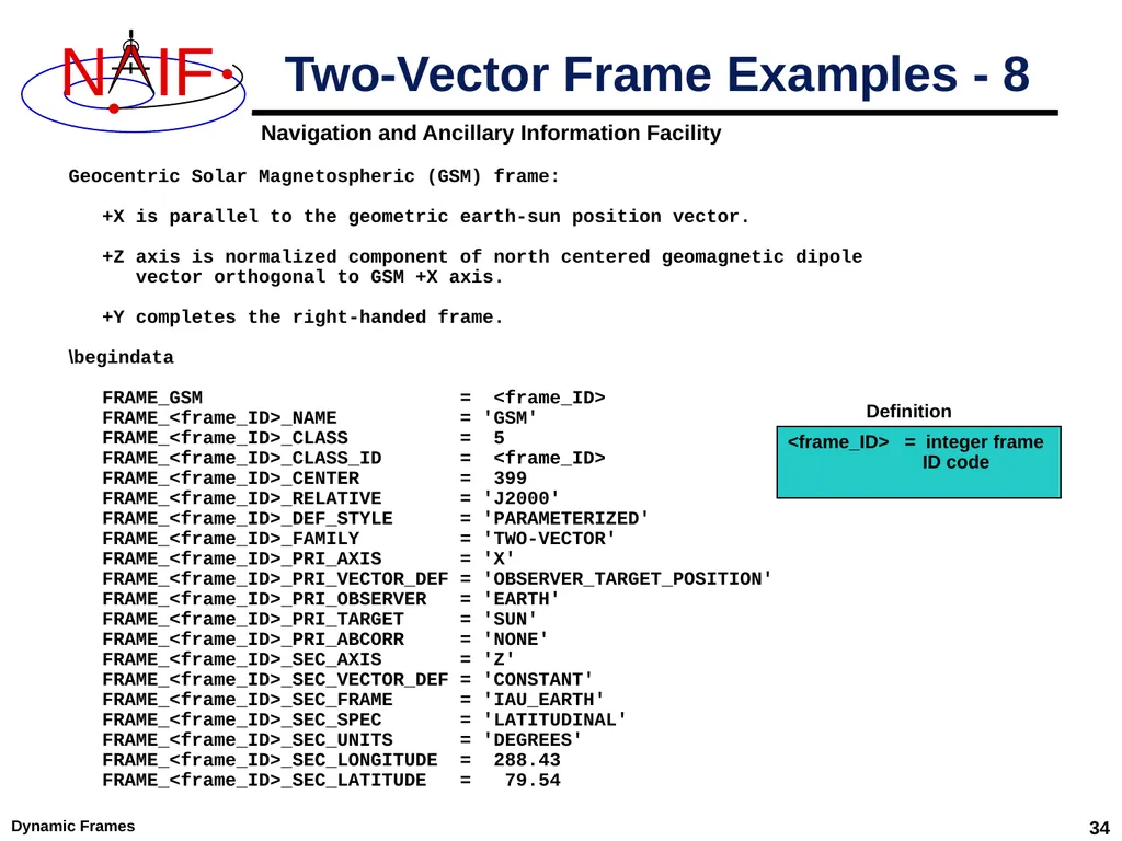
Dynamic Frames 34 Two-Vector Frame Examples - 8 Geocentric Solar Magnetospheric (GSM) frame:
+X is parallel to the geometric earth-sun position vector.
+Z axis is normalized component of north centered geomagnetic dipole
vector orthogonal to GSM +X axis.
+Y completes the right-handed frame.
\begindata
FRAME_GSM = <frame_ID>
FRAME_<frame_ID>_NAME = 'GSM'
FRAME_<frame_ID>_CLASS = 5
FRAME_<frame_ID>_CLASS_ID = <frame_ID>
FRAME_<frame_ID>_CENTER = 399
FRAME_<frame_ID>_RELATIVE = 'J2000'
FRAME_<frame_ID>_DEF_STYLE = 'PARAMETERIZED'
FRAME_<frame_ID>_FAMILY = 'TWO-VECTOR'
FRAME_<frame_ID>_PRI_AXIS = 'X'
FRAME_<frame_ID>_PRI_VECTOR_DEF = 'OBSERVER_TARGET_POSITION'
FRAME_<frame_ID>_PRI_OBSERVER = 'EARTH'
FRAME_<frame_ID>_PRI_TARGET = 'SUN'
FRAME_<frame_ID>_PRI_ABCORR = 'NONE'
FRAME_<frame_ID>_SEC_AXIS = 'Z'
FRAME_<frame_ID>_SEC_VECTOR_DEF = 'CONSTANT'
FRAME_<frame_ID>_SEC_FRAME = 'IAU_EARTH'
FRAME_<frame_ID>_SEC_SPEC = 'LATITUDINAL'
FRAME_<frame_ID>_SEC_UNITS = 'DEGREES'
FRAME_<frame_ID>_SEC_LONGITUDE = 288.43
FRAME_<frame_ID>_SEC_LATITUDE = 79.54 <frame_ID> = integer frame
ID code Definition<br>
+X is parallel to the geometric earth-sun position vector.
+Z axis is normalized component of north centered geomagnetic dipole
vector orthogonal to GSM +X axis.
+Y completes the right-handed frame.
\begindata
FRAME_GSM = <frame_ID>
FRAME_<frame_ID>_NAME = 'GSM'
FRAME_<frame_ID>_CLASS = 5
FRAME_<frame_ID>_CLASS_ID = <frame_ID>
FRAME_<frame_ID>_CENTER = 399
FRAME_<frame_ID>_RELATIVE = 'J2000'
FRAME_<frame_ID>_DEF_STYLE = 'PARAMETERIZED'
FRAME_<frame_ID>_FAMILY = 'TWO-VECTOR'
FRAME_<frame_ID>_PRI_AXIS = 'X'
FRAME_<frame_ID>_PRI_VECTOR_DEF = 'OBSERVER_TARGET_POSITION'
FRAME_<frame_ID>_PRI_OBSERVER = 'EARTH'
FRAME_<frame_ID>_PRI_TARGET = 'SUN'
FRAME_<frame_ID>_PRI_ABCORR = 'NONE'
FRAME_<frame_ID>_SEC_AXIS = 'Z'
FRAME_<frame_ID>_SEC_VECTOR_DEF = 'CONSTANT'
FRAME_<frame_ID>_SEC_FRAME = 'IAU_EARTH'
FRAME_<frame_ID>_SEC_SPEC = 'LATITUDINAL'
FRAME_<frame_ID>_SEC_UNITS = 'DEGREES'
FRAME_<frame_ID>_SEC_LONGITUDE = 288.43
FRAME_<frame_ID>_SEC_LATITUDE = 79.54 <frame_ID> = integer frame
ID code Definition<br>
35
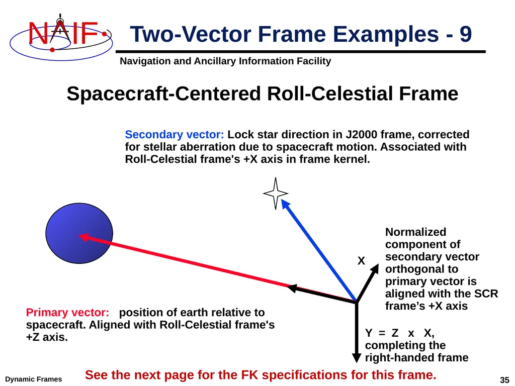
Dynamic Frames 35 Two-Vector Frame Examples - 9 Secondary vector: Lock star direction in J2000 frame, corrected for stellar aberration due to spacecraft motion. Associated with Roll-Celestial frame's +X axis in frame kernel. Spacecraft-Centered Roll-Celestial Frame Primary vector: position of earth relative to spacecraft. Aligned with Roll-Celestial frame's +Z axis. Normalized
component of
secondary vector
orthogonal to
primary vector is aligned with the SCR frame’s +X axis Y = Z x X,
completing the
right-handed frame See the next page for the FK specifications for this frame. X<br>
component of
secondary vector
orthogonal to
primary vector is aligned with the SCR frame’s +X axis Y = Z x X,
completing the
right-handed frame See the next page for the FK specifications for this frame. X<br>
36
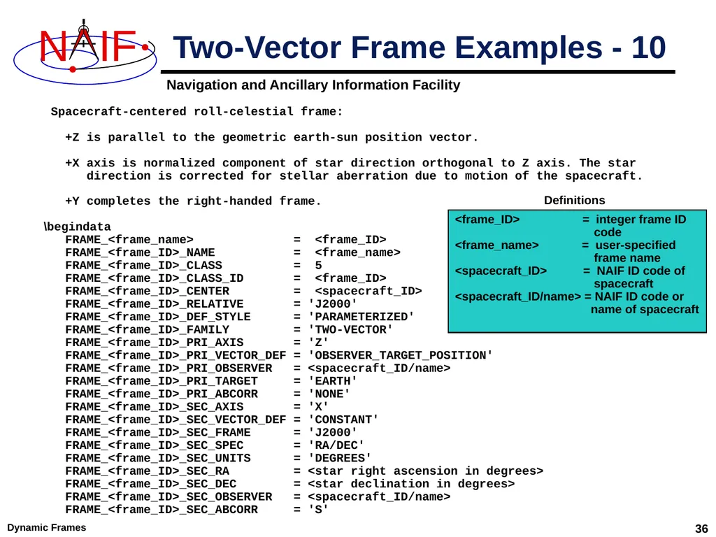
Dynamic Frames 36 Two-Vector Frame Examples - 10 Spacecraft-centered roll-celestial frame:
+Z is parallel to the geometric earth-sun position vector.
+X axis is normalized component of star direction orthogonal to Z axis. The star
direction is corrected for stellar aberration due to motion of the spacecraft.
+Y completes the right-handed frame.
\begindata
FRAME_<frame_name> = <frame_ID>
FRAME_<frame_ID>_NAME = <frame_name>
FRAME_<frame_ID>_CLASS = 5
FRAME_<frame_ID>_CLASS_ID = <frame_ID>
FRAME_<frame_ID>_CENTER = <spacecraft_ID>
FRAME_<frame_ID>_RELATIVE = 'J2000'
FRAME_<frame_ID>_DEF_STYLE = 'PARAMETERIZED'
FRAME_<frame_ID>_FAMILY = 'TWO-VECTOR'
FRAME_<frame_ID>_PRI_AXIS = 'Z'
FRAME_<frame_ID>_PRI_VECTOR_DEF = 'OBSERVER_TARGET_POSITION'
FRAME_<frame_ID>_PRI_OBSERVER = <spacecraft_ID/name>
FRAME_<frame_ID>_PRI_TARGET = 'EARTH'
FRAME_<frame_ID>_PRI_ABCORR = 'NONE'
FRAME_<frame_ID>_SEC_AXIS = 'X'
FRAME_<frame_ID>_SEC_VECTOR_DEF = 'CONSTANT'
FRAME_<frame_ID>_SEC_FRAME = 'J2000'
FRAME_<frame_ID>_SEC_SPEC = 'RA/DEC'
FRAME_<frame_ID>_SEC_UNITS = 'DEGREES'
FRAME_<frame_ID>_SEC_RA = <star right ascension in degrees>
FRAME_<frame_ID>_SEC_DEC = <star declination in degrees>
FRAME_<frame_ID>_SEC_OBSERVER = <spacecraft_ID/name>
FRAME_<frame_ID>_SEC_ABCORR = 'S' <frame_ID> = integer frame ID
code
<frame_name> = user-specified
frame name
<spacecraft_ID> = NAIF ID code of
spacecraft
<spacecraft_ID/name> = NAIF ID code or
name of spacecraft Definitions<br>
+Z is parallel to the geometric earth-sun position vector.
+X axis is normalized component of star direction orthogonal to Z axis. The star
direction is corrected for stellar aberration due to motion of the spacecraft.
+Y completes the right-handed frame.
\begindata
FRAME_<frame_name> = <frame_ID>
FRAME_<frame_ID>_NAME = <frame_name>
FRAME_<frame_ID>_CLASS = 5
FRAME_<frame_ID>_CLASS_ID = <frame_ID>
FRAME_<frame_ID>_CENTER = <spacecraft_ID>
FRAME_<frame_ID>_RELATIVE = 'J2000'
FRAME_<frame_ID>_DEF_STYLE = 'PARAMETERIZED'
FRAME_<frame_ID>_FAMILY = 'TWO-VECTOR'
FRAME_<frame_ID>_PRI_AXIS = 'Z'
FRAME_<frame_ID>_PRI_VECTOR_DEF = 'OBSERVER_TARGET_POSITION'
FRAME_<frame_ID>_PRI_OBSERVER = <spacecraft_ID/name>
FRAME_<frame_ID>_PRI_TARGET = 'EARTH'
FRAME_<frame_ID>_PRI_ABCORR = 'NONE'
FRAME_<frame_ID>_SEC_AXIS = 'X'
FRAME_<frame_ID>_SEC_VECTOR_DEF = 'CONSTANT'
FRAME_<frame_ID>_SEC_FRAME = 'J2000'
FRAME_<frame_ID>_SEC_SPEC = 'RA/DEC'
FRAME_<frame_ID>_SEC_UNITS = 'DEGREES'
FRAME_<frame_ID>_SEC_RA = <star right ascension in degrees>
FRAME_<frame_ID>_SEC_DEC = <star declination in degrees>
FRAME_<frame_ID>_SEC_OBSERVER = <spacecraft_ID/name>
FRAME_<frame_ID>_SEC_ABCORR = 'S' <frame_ID> = integer frame ID
code
<frame_name> = user-specified
frame name
<spacecraft_ID> = NAIF ID code of
spacecraft
<spacecraft_ID/name> = NAIF ID code or
name of spacecraft Definitions<br>
37
Dynamic Frames 37 Of-date frames are associated with user-specified bodies and are based on user-selected dynamical models.
Implementations of these models are built into SPICE.
The currently supported "of-date" frame families are
Mean Equator and Equinox of Date
True Equator and Equinox of Date
Mean Ecliptic and Equinox of Date
Currently the Earth is the only supported body for of-date dynamic frames. "Of-Date" Frames - 1<br>
Implementations of these models are built into SPICE.
The currently supported "of-date" frame families are
Mean Equator and Equinox of Date
True Equator and Equinox of Date
Mean Ecliptic and Equinox of Date
Currently the Earth is the only supported body for of-date dynamic frames. "Of-Date" Frames - 1<br>
38
Dynamic Frames 38 The supported types of models are:
Precession
Nutation
Mean obliquity
The of-date frame implementation is intended to be flexible…
The set of supported bodies can grow over time.
The set of supported models can grow over time.
SPICE is not forever locked into using a single hard-coded implementation, such as the 1976 IAU precession model. "Of-Date" Frames - 2<br>
Precession
Nutation
Mean obliquity
The of-date frame implementation is intended to be flexible…
The set of supported bodies can grow over time.
The set of supported models can grow over time.
SPICE is not forever locked into using a single hard-coded implementation, such as the 1976 IAU precession model. "Of-Date" Frames - 2<br>
39
Dynamic Frames 39 Mean Equator and Equinox of Date Family
For all reference frames in this family…
The frame's relationship to the J2000 frame is given by a precession model.
The frame kernel creator selects a precession model from those built into the SPICE software.
Currently supported only for the Earth, and only the 1976 IAU precession model (Lieske model)
The frame kernel creator must either specify the frame's rotation state or must designate the frame “frozen” at a specified “freeze epoch” (but not both). "Of-Date" Frames - 3<br>
For all reference frames in this family…
The frame's relationship to the J2000 frame is given by a precession model.
The frame kernel creator selects a precession model from those built into the SPICE software.
Currently supported only for the Earth, and only the 1976 IAU precession model (Lieske model)
The frame kernel creator must either specify the frame's rotation state or must designate the frame “frozen” at a specified “freeze epoch” (but not both). "Of-Date" Frames - 3<br>
40
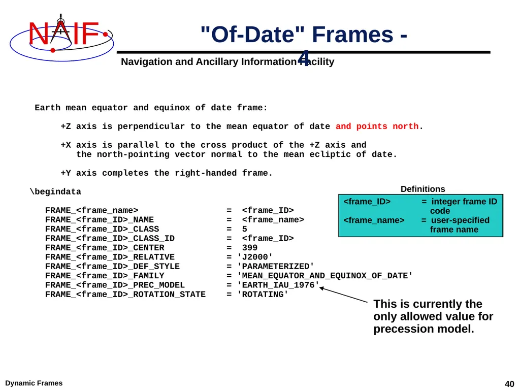
Dynamic Frames 40 "Of-Date" Frames - 4 Earth mean equator and equinox of date frame:
+Z axis is perpendicular to the mean equator of date and points north.
+X axis is parallel to the cross product of the +Z axis and
the north-pointing vector normal to the mean ecliptic of date.
+Y axis completes the right-handed frame.
\begindata
FRAME_<frame_name> = <frame_ID>
FRAME_<frame_ID>_NAME = <frame_name>
FRAME_<frame_ID>_CLASS = 5
FRAME_<frame_ID>_CLASS_ID = <frame_ID>
FRAME_<frame_ID>_CENTER = 399
FRAME_<frame_ID>_RELATIVE = 'J2000'
FRAME_<frame_ID>_DEF_STYLE = 'PARAMETERIZED'
FRAME_<frame_ID>_FAMILY = 'MEAN_EQUATOR_AND_EQUINOX_OF_DATE'
FRAME_<frame_ID>_PREC_MODEL = 'EARTH_IAU_1976'
FRAME_<frame_ID>_ROTATION_STATE = 'ROTATING' <frame_ID> = integer frame ID
code
<frame_name> = user-specified
frame name Definitions This is currently the
only allowed value for
precession model.<br>
+Z axis is perpendicular to the mean equator of date and points north.
+X axis is parallel to the cross product of the +Z axis and
the north-pointing vector normal to the mean ecliptic of date.
+Y axis completes the right-handed frame.
\begindata
FRAME_<frame_name> = <frame_ID>
FRAME_<frame_ID>_NAME = <frame_name>
FRAME_<frame_ID>_CLASS = 5
FRAME_<frame_ID>_CLASS_ID = <frame_ID>
FRAME_<frame_ID>_CENTER = 399
FRAME_<frame_ID>_RELATIVE = 'J2000'
FRAME_<frame_ID>_DEF_STYLE = 'PARAMETERIZED'
FRAME_<frame_ID>_FAMILY = 'MEAN_EQUATOR_AND_EQUINOX_OF_DATE'
FRAME_<frame_ID>_PREC_MODEL = 'EARTH_IAU_1976'
FRAME_<frame_ID>_ROTATION_STATE = 'ROTATING' <frame_ID> = integer frame ID
code
<frame_name> = user-specified
frame name Definitions This is currently the
only allowed value for
precession model.<br>
41
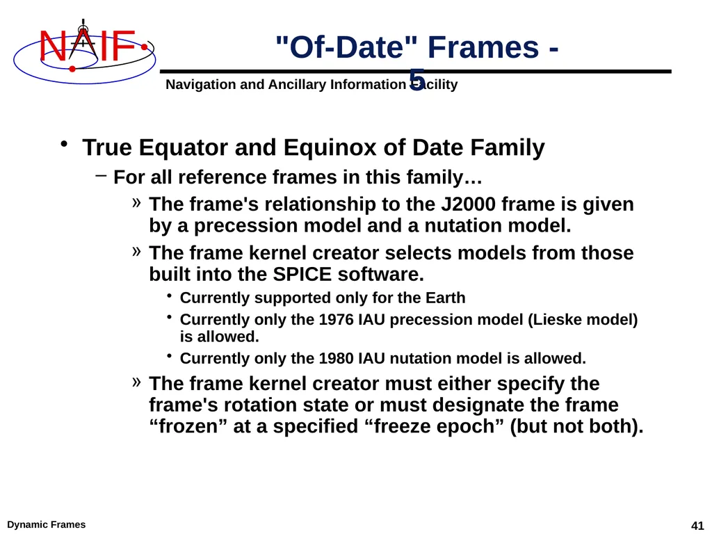
Dynamic Frames 41 True Equator and Equinox of Date Family
For all reference frames in this family…
The frame's relationship to the J2000 frame is given by a precession model and a nutation model.
The frame kernel creator selects models from those built into the SPICE software.
Currently supported only for the Earth
Currently only the 1976 IAU precession model (Lieske model) is allowed.
Currently only the 1980 IAU nutation model is allowed.
The frame kernel creator must either specify the frame's rotation state or must designate the frame “frozen” at a specified “freeze epoch” (but not both). "Of-Date" Frames - 5<br>
For all reference frames in this family…
The frame's relationship to the J2000 frame is given by a precession model and a nutation model.
The frame kernel creator selects models from those built into the SPICE software.
Currently supported only for the Earth
Currently only the 1976 IAU precession model (Lieske model) is allowed.
Currently only the 1980 IAU nutation model is allowed.
The frame kernel creator must either specify the frame's rotation state or must designate the frame “frozen” at a specified “freeze epoch” (but not both). "Of-Date" Frames - 5<br>
42
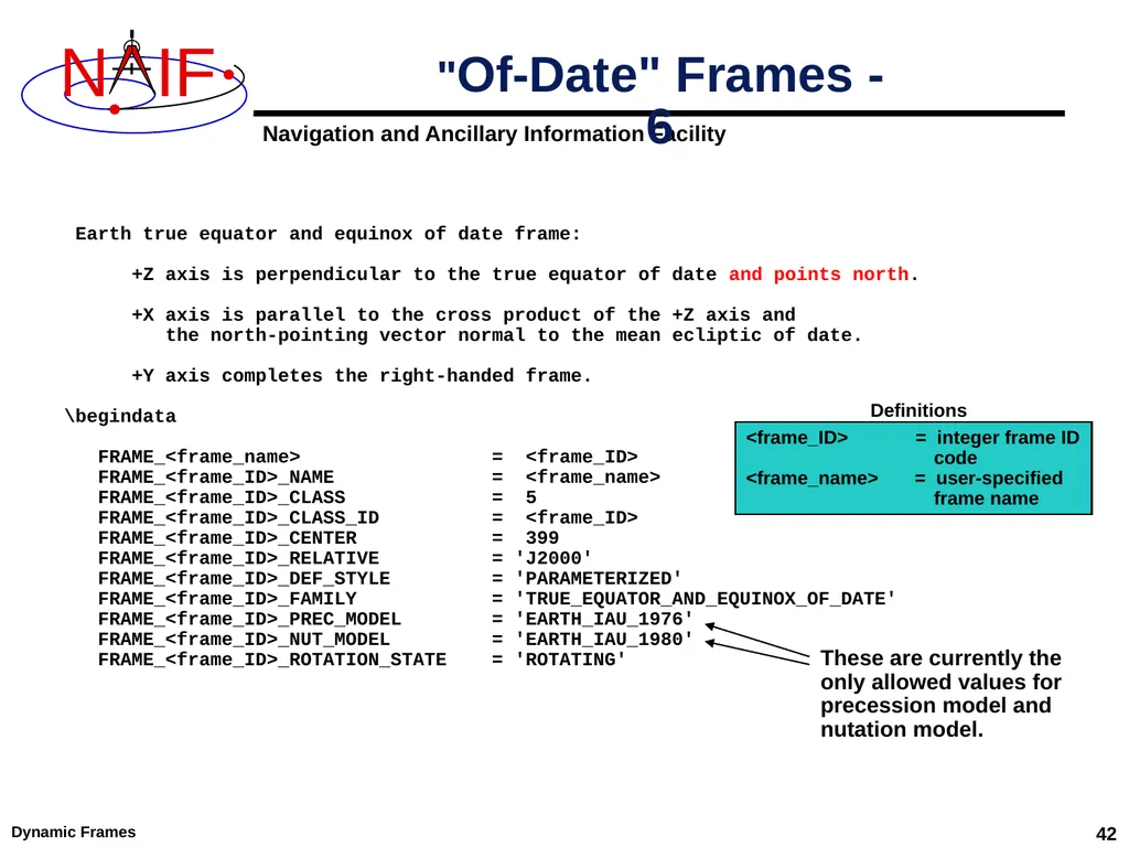
Dynamic Frames 42 "Of-Date" Frames - 6 Earth true equator and equinox of date frame:
+Z axis is perpendicular to the true equator of date and points north.
+X axis is parallel to the cross product of the +Z axis and
the north-pointing vector normal to the mean ecliptic of date.
+Y axis completes the right-handed frame.
\begindata
FRAME_<frame_name> = <frame_ID>
FRAME_<frame_ID>_NAME = <frame_name>
FRAME_<frame_ID>_CLASS = 5
FRAME_<frame_ID>_CLASS_ID = <frame_ID>
FRAME_<frame_ID>_CENTER = 399
FRAME_<frame_ID>_RELATIVE = 'J2000'
FRAME_<frame_ID>_DEF_STYLE = 'PARAMETERIZED'
FRAME_<frame_ID>_FAMILY = 'TRUE_EQUATOR_AND_EQUINOX_OF_DATE'
FRAME_<frame_ID>_PREC_MODEL = 'EARTH_IAU_1976'
FRAME_<frame_ID>_NUT_MODEL = 'EARTH_IAU_1980'
FRAME_<frame_ID>_ROTATION_STATE = 'ROTATING' <frame_ID> = integer frame ID
code
<frame_name> = user-specified
frame name Definitions These are currently the
only allowed values for
precession model and nutation model.<br>
+Z axis is perpendicular to the true equator of date and points north.
+X axis is parallel to the cross product of the +Z axis and
the north-pointing vector normal to the mean ecliptic of date.
+Y axis completes the right-handed frame.
\begindata
FRAME_<frame_name> = <frame_ID>
FRAME_<frame_ID>_NAME = <frame_name>
FRAME_<frame_ID>_CLASS = 5
FRAME_<frame_ID>_CLASS_ID = <frame_ID>
FRAME_<frame_ID>_CENTER = 399
FRAME_<frame_ID>_RELATIVE = 'J2000'
FRAME_<frame_ID>_DEF_STYLE = 'PARAMETERIZED'
FRAME_<frame_ID>_FAMILY = 'TRUE_EQUATOR_AND_EQUINOX_OF_DATE'
FRAME_<frame_ID>_PREC_MODEL = 'EARTH_IAU_1976'
FRAME_<frame_ID>_NUT_MODEL = 'EARTH_IAU_1980'
FRAME_<frame_ID>_ROTATION_STATE = 'ROTATING' <frame_ID> = integer frame ID
code
<frame_name> = user-specified
frame name Definitions These are currently the
only allowed values for
precession model and nutation model.<br>
43
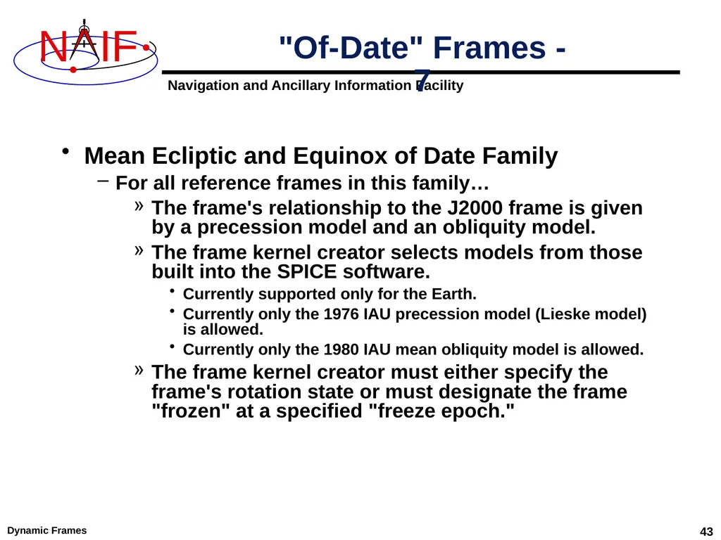
Dynamic Frames 43 Mean Ecliptic and Equinox of Date Family
For all reference frames in this family…
The frame's relationship to the J2000 frame is given by a precession model and an obliquity model.
The frame kernel creator selects models from those built into the SPICE software.
Currently supported only for the Earth.
Currently only the 1976 IAU precession model (Lieske model) is allowed.
Currently only the 1980 IAU mean obliquity model is allowed.
The frame kernel creator must either specify the frame's rotation state or must designate the frame "frozen" at a specified "freeze epoch." "Of-Date" Frames - 7<br>
For all reference frames in this family…
The frame's relationship to the J2000 frame is given by a precession model and an obliquity model.
The frame kernel creator selects models from those built into the SPICE software.
Currently supported only for the Earth.
Currently only the 1976 IAU precession model (Lieske model) is allowed.
Currently only the 1980 IAU mean obliquity model is allowed.
The frame kernel creator must either specify the frame's rotation state or must designate the frame "frozen" at a specified "freeze epoch." "Of-Date" Frames - 7<br>
44
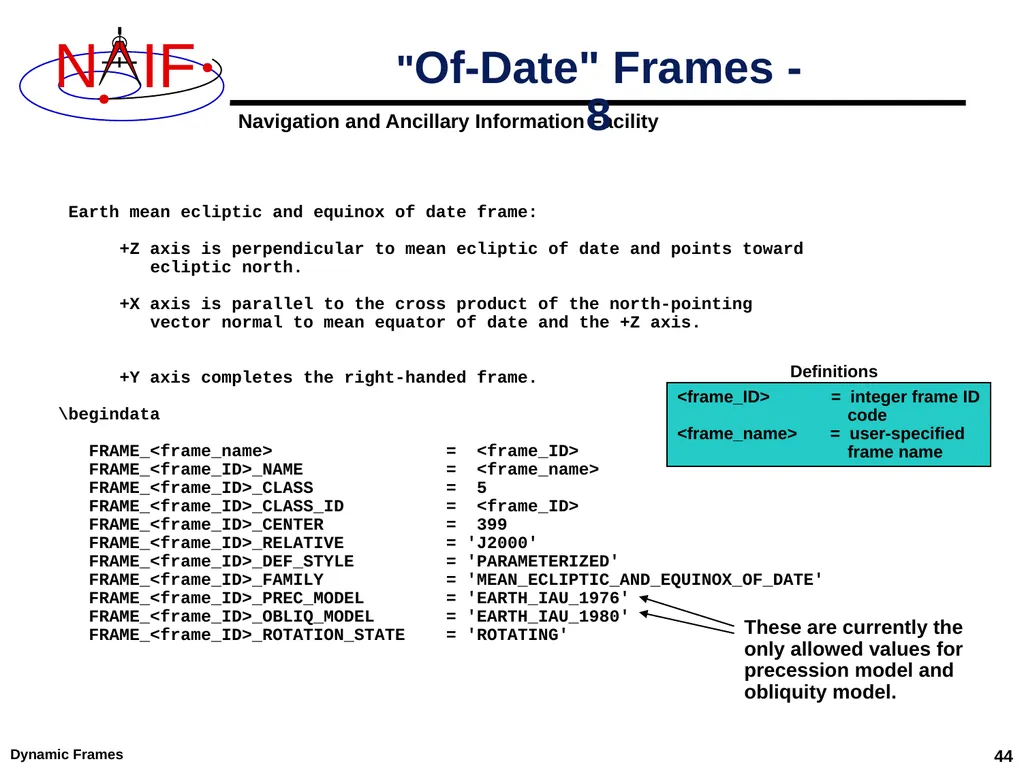
Dynamic Frames 44 "Of-Date" Frames - 8 Earth mean ecliptic and equinox of date frame:
+Z axis is perpendicular to mean ecliptic of date and points toward
ecliptic north.
+X axis is parallel to the cross product of the north-pointing
vector normal to mean equator of date and the +Z axis.
+Y axis completes the right-handed frame.
\begindata
FRAME_<frame_name> = <frame_ID>
FRAME_<frame_ID>_NAME = <frame_name>
FRAME_<frame_ID>_CLASS = 5
FRAME_<frame_ID>_CLASS_ID = <frame_ID>
FRAME_<frame_ID>_CENTER = 399
FRAME_<frame_ID>_RELATIVE = 'J2000'
FRAME_<frame_ID>_DEF_STYLE = 'PARAMETERIZED'
FRAME_<frame_ID>_FAMILY = 'MEAN_ECLIPTIC_AND_EQUINOX_OF_DATE'
FRAME_<frame_ID>_PREC_MODEL = 'EARTH_IAU_1976'
FRAME_<frame_ID>_OBLIQ_MODEL = 'EARTH_IAU_1980'
FRAME_<frame_ID>_ROTATION_STATE = 'ROTATING' <frame_ID> = integer frame ID
code
<frame_name> = user-specified
frame name Definitions These are currently the
only allowed values for
precession model and obliquity model.<br>
+Z axis is perpendicular to mean ecliptic of date and points toward
ecliptic north.
+X axis is parallel to the cross product of the north-pointing
vector normal to mean equator of date and the +Z axis.
+Y axis completes the right-handed frame.
\begindata
FRAME_<frame_name> = <frame_ID>
FRAME_<frame_ID>_NAME = <frame_name>
FRAME_<frame_ID>_CLASS = 5
FRAME_<frame_ID>_CLASS_ID = <frame_ID>
FRAME_<frame_ID>_CENTER = 399
FRAME_<frame_ID>_RELATIVE = 'J2000'
FRAME_<frame_ID>_DEF_STYLE = 'PARAMETERIZED'
FRAME_<frame_ID>_FAMILY = 'MEAN_ECLIPTIC_AND_EQUINOX_OF_DATE'
FRAME_<frame_ID>_PREC_MODEL = 'EARTH_IAU_1976'
FRAME_<frame_ID>_OBLIQ_MODEL = 'EARTH_IAU_1980'
FRAME_<frame_ID>_ROTATION_STATE = 'ROTATING' <frame_ID> = integer frame ID
code
<frame_name> = user-specified
frame name Definitions These are currently the
only allowed values for
precession model and obliquity model.<br>
45
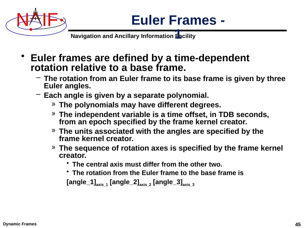
Dynamic Frames 45 Euler frames are defined by a time-dependent rotation relative to a base frame.
The rotation from an Euler frame to its base frame is given by three Euler angles.
Each angle is given by a separate polynomial.
The polynomials may have different degrees.
The independent variable is a time offset, in TDB seconds, from an epoch specified by the frame kernel creator.
The units associated with the angles are specified by the frame kernel creator.
The sequence of rotation axes is specified by the frame kernel creator.
The central axis must differ from the other two.
The rotation from the Euler frame to the base frame is
[angle_1]axis_1 [angle_2]axis_2 [angle_3]axis_3 Euler Frames - 1<br>
The rotation from an Euler frame to its base frame is given by three Euler angles.
Each angle is given by a separate polynomial.
The polynomials may have different degrees.
The independent variable is a time offset, in TDB seconds, from an epoch specified by the frame kernel creator.
The units associated with the angles are specified by the frame kernel creator.
The sequence of rotation axes is specified by the frame kernel creator.
The central axis must differ from the other two.
The rotation from the Euler frame to the base frame is
[angle_1]axis_1 [angle_2]axis_2 [angle_3]axis_3 Euler Frames - 1<br>
46
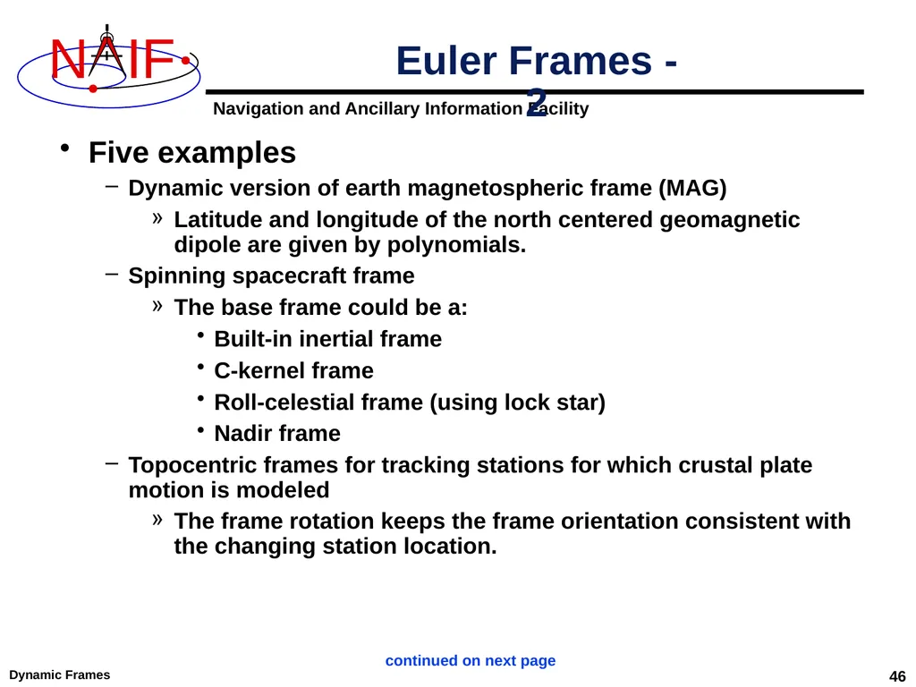
Dynamic Frames 46 Five examples
Dynamic version of earth magnetospheric frame (MAG)
Latitude and longitude of the north centered geomagnetic dipole are given by polynomials.
Spinning spacecraft frame
The base frame could be a:
Built-in inertial frame
C-kernel frame
Roll-celestial frame (using lock star)
Nadir frame
Topocentric frames for tracking stations for which crustal plate motion is modeled
The frame rotation keeps the frame orientation consistent with the changing station location. Euler Frames - 2 continued on next page<br>
Dynamic version of earth magnetospheric frame (MAG)
Latitude and longitude of the north centered geomagnetic dipole are given by polynomials.
Spinning spacecraft frame
The base frame could be a:
Built-in inertial frame
C-kernel frame
Roll-celestial frame (using lock star)
Nadir frame
Topocentric frames for tracking stations for which crustal plate motion is modeled
The frame rotation keeps the frame orientation consistent with the changing station location. Euler Frames - 2 continued on next page<br>
47
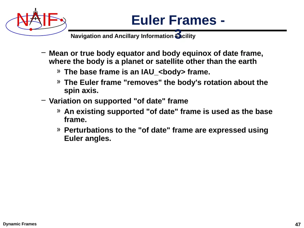
Dynamic Frames 47 Mean or true body equator and body equinox of date frame, where the body is a planet or satellite other than the earth
The base frame is an IAU_<body> frame.
The Euler frame "removes" the body's rotation about the spin axis.
Variation on supported "of date" frame
An existing supported "of date" frame is used as the base frame.
Perturbations to the "of date" frame are expressed using Euler angles. Euler Frames - 3<br>
The base frame is an IAU_<body> frame.
The Euler frame "removes" the body's rotation about the spin axis.
Variation on supported "of date" frame
An existing supported "of date" frame is used as the base frame.
Perturbations to the "of date" frame are expressed using Euler angles. Euler Frames - 3<br>
48
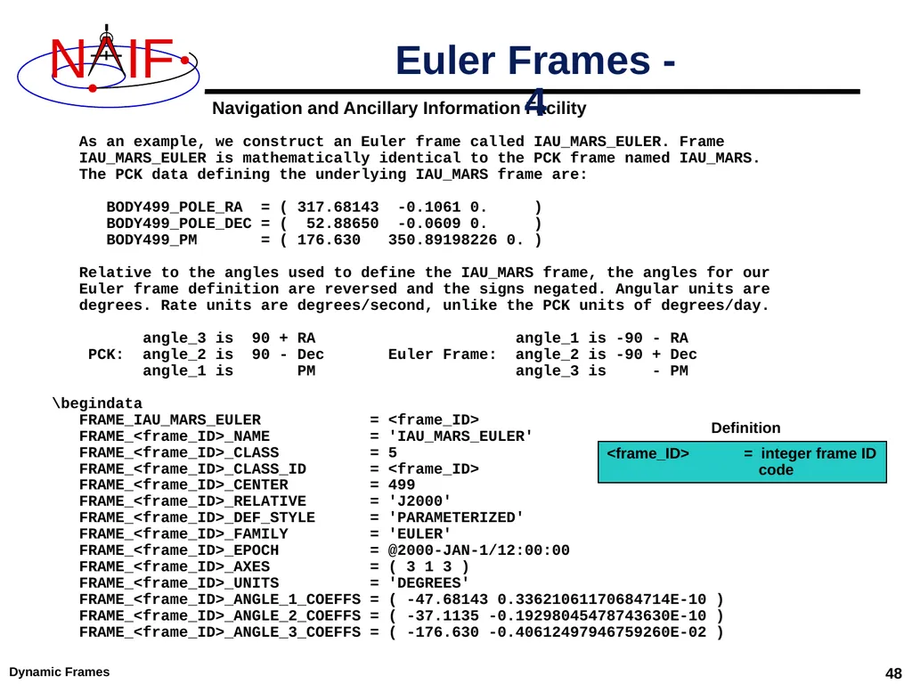
Dynamic Frames 48 Euler Frames - 4 As an example, we construct an Euler frame called IAU_MARS_EULER. Frame
IAU_MARS_EULER is mathematically identical to the PCK frame named IAU_MARS.
The PCK data defining the underlying IAU_MARS frame are:
BODY499_POLE_RA = ( 317.68143 -0.1061 0. )
BODY499_POLE_DEC = ( 52.88650 -0.0609 0. )
BODY499_PM = ( 176.630 350.89198226 0. )
Relative to the angles used to define the IAU_MARS frame, the angles for our
Euler frame definition are reversed and the signs negated. Angular units are
degrees. Rate units are degrees/second, unlike the PCK units of degrees/day.
angle_3 is 90 + RA angle_1 is -90 - RA
PCK: angle_2 is 90 - Dec Euler Frame: angle_2 is -90 + Dec
angle_1 is PM angle_3 is - PM
\begindata
FRAME_IAU_MARS_EULER = <frame_ID>
FRAME_<frame_ID>_NAME = 'IAU_MARS_EULER'
FRAME_<frame_ID>_CLASS = 5
FRAME_<frame_ID>_CLASS_ID = <frame_ID>
FRAME_<frame_ID>_CENTER = 499
FRAME_<frame_ID>_RELATIVE = 'J2000'
FRAME_<frame_ID>_DEF_STYLE = 'PARAMETERIZED'
FRAME_<frame_ID>_FAMILY = 'EULER'
FRAME_<frame_ID>_EPOCH = @2000-JAN-1/12:00:00
FRAME_<frame_ID>_AXES = ( 3 1 3 )
FRAME_<frame_ID>_UNITS = 'DEGREES'
FRAME_<frame_ID>_ANGLE_1_COEFFS = ( -47.68143 0.33621061170684714E-10 )
FRAME_<frame_ID>_ANGLE_2_COEFFS = ( -37.1135 -0.19298045478743630E-10 )
FRAME_<frame_ID>_ANGLE_3_COEFFS = ( -176.630 -0.40612497946759260E-02 ) <frame_ID> = integer frame ID
code Definition<br>
IAU_MARS_EULER is mathematically identical to the PCK frame named IAU_MARS.
The PCK data defining the underlying IAU_MARS frame are:
BODY499_POLE_RA = ( 317.68143 -0.1061 0. )
BODY499_POLE_DEC = ( 52.88650 -0.0609 0. )
BODY499_PM = ( 176.630 350.89198226 0. )
Relative to the angles used to define the IAU_MARS frame, the angles for our
Euler frame definition are reversed and the signs negated. Angular units are
degrees. Rate units are degrees/second, unlike the PCK units of degrees/day.
angle_3 is 90 + RA angle_1 is -90 - RA
PCK: angle_2 is 90 - Dec Euler Frame: angle_2 is -90 + Dec
angle_1 is PM angle_3 is - PM
\begindata
FRAME_IAU_MARS_EULER = <frame_ID>
FRAME_<frame_ID>_NAME = 'IAU_MARS_EULER'
FRAME_<frame_ID>_CLASS = 5
FRAME_<frame_ID>_CLASS_ID = <frame_ID>
FRAME_<frame_ID>_CENTER = 499
FRAME_<frame_ID>_RELATIVE = 'J2000'
FRAME_<frame_ID>_DEF_STYLE = 'PARAMETERIZED'
FRAME_<frame_ID>_FAMILY = 'EULER'
FRAME_<frame_ID>_EPOCH = @2000-JAN-1/12:00:00
FRAME_<frame_ID>_AXES = ( 3 1 3 )
FRAME_<frame_ID>_UNITS = 'DEGREES'
FRAME_<frame_ID>_ANGLE_1_COEFFS = ( -47.68143 0.33621061170684714E-10 )
FRAME_<frame_ID>_ANGLE_2_COEFFS = ( -37.1135 -0.19298045478743630E-10 )
FRAME_<frame_ID>_ANGLE_3_COEFFS = ( -176.630 -0.40612497946759260E-02 ) <frame_ID> = integer frame ID
code Definition<br>
49
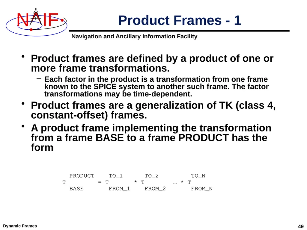
Product frames are defined by a product of one or more frame transformations.
Each factor in the product is a transformation from one frame known to the SPICE system to another such frame. The factor transformations may be time-dependent.
Product frames are a generalization of TK (class 4, constant-offset) frames.
A product frame implementing the transformation from a frame BASE to a frame PRODUCT has the form Dynamic Frames 49 Product Frames - 1 PRODUCT TO_1 TO_2 TO_N
T = T * T … * T
BASE FROM_1 FROM_2 FROM_N<br>
Each factor in the product is a transformation from one frame known to the SPICE system to another such frame. The factor transformations may be time-dependent.
Product frames are a generalization of TK (class 4, constant-offset) frames.
A product frame implementing the transformation from a frame BASE to a frame PRODUCT has the form Dynamic Frames 49 Product Frames - 1 PRODUCT TO_1 TO_2 TO_N
T = T * T … * T
BASE FROM_1 FROM_2 FROM_N<br>
50
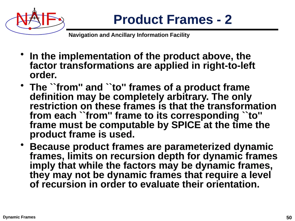
In the implementation of the product above, the factor transformations are applied in right-to-left order.
The ``from'' and ``to'' frames of a product frame definition may be completely arbitrary. The only restriction on these frames is that the transformation from each ``from'' frame to its corresponding ``to'' frame must be computable by SPICE at the time the product frame is used.
Because product frames are parameterized dynamic frames, limits on recursion depth for dynamic frames imply that while the factors may be dynamic frames, they may not be dynamic frames that require a level of recursion in order to evaluate their orientation. Dynamic Frames 50 Product Frames - 2<br>
The ``from'' and ``to'' frames of a product frame definition may be completely arbitrary. The only restriction on these frames is that the transformation from each ``from'' frame to its corresponding ``to'' frame must be computable by SPICE at the time the product frame is used.
Because product frames are parameterized dynamic frames, limits on recursion depth for dynamic frames imply that while the factors may be dynamic frames, they may not be dynamic frames that require a level of recursion in order to evaluate their orientation. Dynamic Frames 50 Product Frames - 2<br>
51
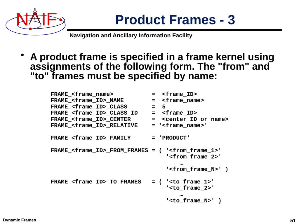
A product frame is specified in a frame kernel using assignments of the following form. The "from" and "to" frames must be specified by name: Dynamic Frames 51 Product Frames - 3 FRAME_<frame_name> = <frame_ID>
FRAME_<frame_ID>_NAME = <frame_name>
FRAME_<frame_ID>_CLASS = 5
FRAME_<frame_ID>_CLASS_ID = <frame_ID>
FRAME_<frame_ID>_CENTER = <center ID or name>
FRAME_<frame_ID>_RELATIVE = '<frame_name>'
FRAME_<frame_ID>_FAMILY = 'PRODUCT'
FRAME_<frame_ID>_FROM_FRAMES = ( '<from_frame_1>'
'<from_frame_2>'
…
'<from_frame_N>' )
FRAME_<frame_ID>_TO_FRAMES = ( '<to_frame_1>'
'<to_frame_2>'
…
'<to_frame_N>' )<br>
FRAME_<frame_ID>_NAME = <frame_name>
FRAME_<frame_ID>_CLASS = 5
FRAME_<frame_ID>_CLASS_ID = <frame_ID>
FRAME_<frame_ID>_CENTER = <center ID or name>
FRAME_<frame_ID>_RELATIVE = '<frame_name>'
FRAME_<frame_ID>_FAMILY = 'PRODUCT'
FRAME_<frame_ID>_FROM_FRAMES = ( '<from_frame_1>'
'<from_frame_2>'
…
'<from_frame_N>' )
FRAME_<frame_ID>_TO_FRAMES = ( '<to_frame_1>'
'<to_frame_2>'
…
'<to_frame_N>' )<br>
52
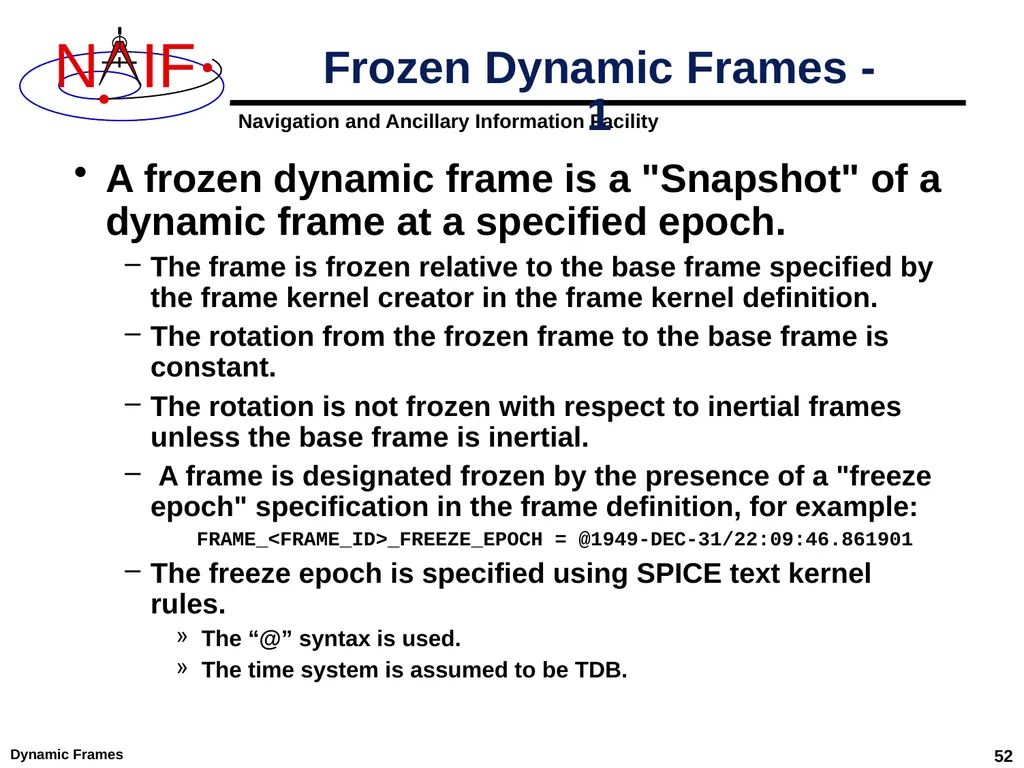
Dynamic Frames 52 A frozen dynamic frame is a "Snapshot" of a dynamic frame at a specified epoch.
The frame is frozen relative to the base frame specified by the frame kernel creator in the frame kernel definition.
The rotation from the frozen frame to the base frame is constant.
The rotation is not frozen with respect to inertial frames unless the base frame is inertial.
A frame is designated frozen by the presence of a "freeze epoch" specification in the frame definition, for example:
FRAME_<FRAME_ID>_FREEZE_EPOCH = @1949-DEC-31/22:09:46.861901
The freeze epoch is specified using SPICE text kernel rules.
The “@” syntax is used.
The time system is assumed to be TDB. Frozen Dynamic Frames - 1<br>
The frame is frozen relative to the base frame specified by the frame kernel creator in the frame kernel definition.
The rotation from the frozen frame to the base frame is constant.
The rotation is not frozen with respect to inertial frames unless the base frame is inertial.
A frame is designated frozen by the presence of a "freeze epoch" specification in the frame definition, for example:
FRAME_<FRAME_ID>_FREEZE_EPOCH = @1949-DEC-31/22:09:46.861901
The freeze epoch is specified using SPICE text kernel rules.
The “@” syntax is used.
The time system is assumed to be TDB. Frozen Dynamic Frames - 1<br>
53
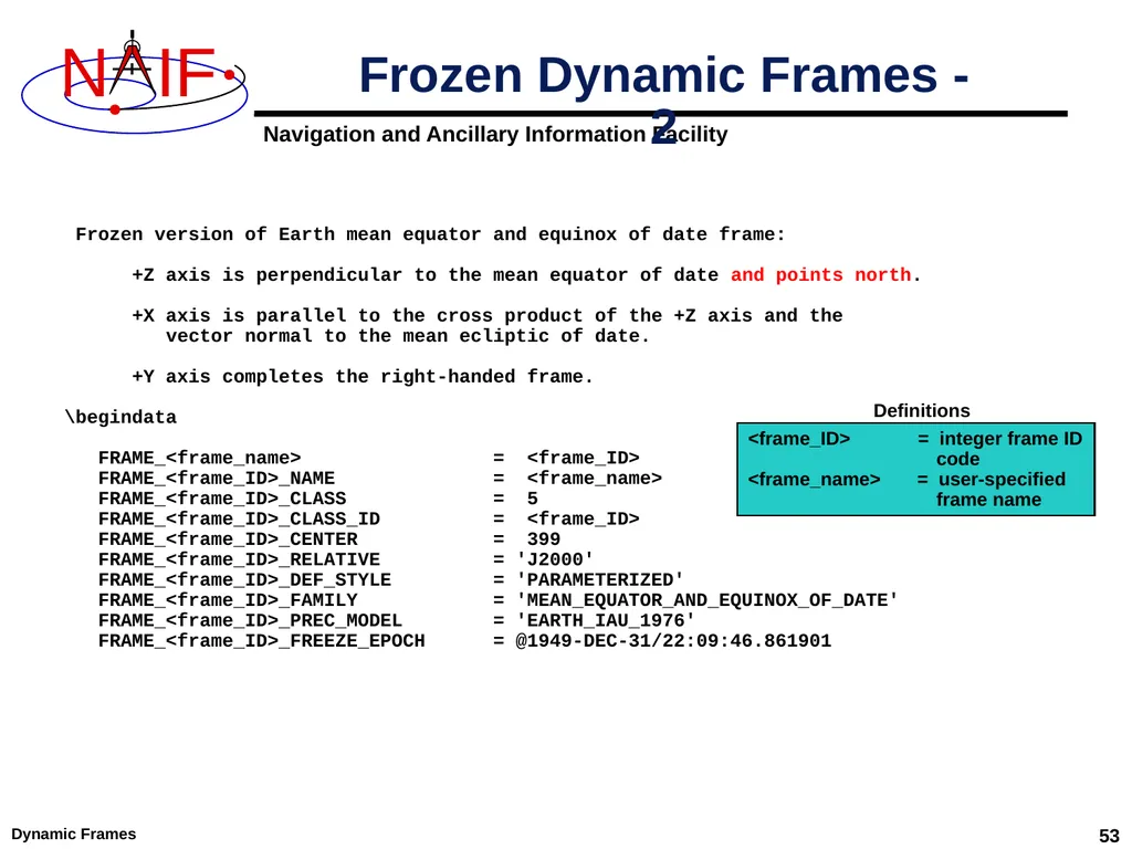
Dynamic Frames 53 Frozen Dynamic Frames - 2 Frozen version of Earth mean equator and equinox of date frame:
+Z axis is perpendicular to the mean equator of date and points north.
+X axis is parallel to the cross product of the +Z axis and the
vector normal to the mean ecliptic of date.
+Y axis completes the right-handed frame.
\begindata
FRAME_<frame_name> = <frame_ID>
FRAME_<frame_ID>_NAME = <frame_name>
FRAME_<frame_ID>_CLASS = 5
FRAME_<frame_ID>_CLASS_ID = <frame_ID>
FRAME_<frame_ID>_CENTER = 399
FRAME_<frame_ID>_RELATIVE = 'J2000'
FRAME_<frame_ID>_DEF_STYLE = 'PARAMETERIZED'
FRAME_<frame_ID>_FAMILY = 'MEAN_EQUATOR_AND_EQUINOX_OF_DATE'
FRAME_<frame_ID>_PREC_MODEL = 'EARTH_IAU_1976'
FRAME_<frame_ID>_FREEZE_EPOCH = @1949-DEC-31/22:09:46.861901 <frame_ID> = integer frame ID
code
<frame_name> = user-specified
frame name Definitions<br>
+Z axis is perpendicular to the mean equator of date and points north.
+X axis is parallel to the cross product of the +Z axis and the
vector normal to the mean ecliptic of date.
+Y axis completes the right-handed frame.
\begindata
FRAME_<frame_name> = <frame_ID>
FRAME_<frame_ID>_NAME = <frame_name>
FRAME_<frame_ID>_CLASS = 5
FRAME_<frame_ID>_CLASS_ID = <frame_ID>
FRAME_<frame_ID>_CENTER = 399
FRAME_<frame_ID>_RELATIVE = 'J2000'
FRAME_<frame_ID>_DEF_STYLE = 'PARAMETERIZED'
FRAME_<frame_ID>_FAMILY = 'MEAN_EQUATOR_AND_EQUINOX_OF_DATE'
FRAME_<frame_ID>_PREC_MODEL = 'EARTH_IAU_1976'
FRAME_<frame_ID>_FREEZE_EPOCH = @1949-DEC-31/22:09:46.861901 <frame_ID> = integer frame ID
code
<frame_name> = user-specified
frame name Definitions<br>
54
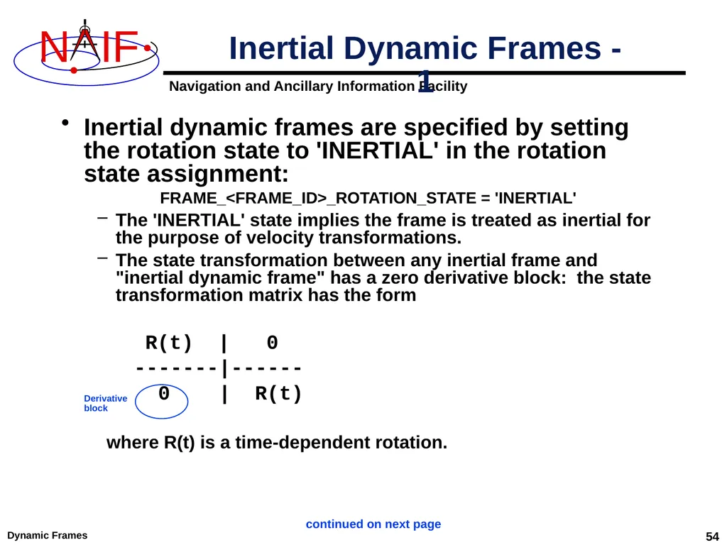
Dynamic Frames 54 Inertial dynamic frames are specified by setting the rotation state to 'INERTIAL' in the rotation state assignment:
FRAME_<FRAME_ID>_ROTATION_STATE = 'INERTIAL'
The 'INERTIAL' state implies the frame is treated as inertial for the purpose of velocity transformations.
The state transformation between any inertial frame and "inertial dynamic frame" has a zero derivative block: the state transformation matrix has the form
R(t) | 0
-------|------
0 | R(t)
where R(t) is a time-dependent rotation. Inertial Dynamic Frames - 1 Derivative
block continued on next page<br>
FRAME_<FRAME_ID>_ROTATION_STATE = 'INERTIAL'
The 'INERTIAL' state implies the frame is treated as inertial for the purpose of velocity transformations.
The state transformation between any inertial frame and "inertial dynamic frame" has a zero derivative block: the state transformation matrix has the form
R(t) | 0
-------|------
0 | R(t)
where R(t) is a time-dependent rotation. Inertial Dynamic Frames - 1 Derivative
block continued on next page<br>
55
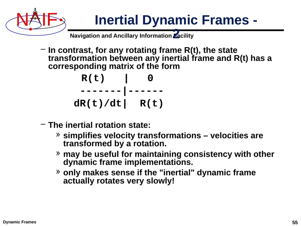
Dynamic Frames 55 In contrast, for any rotating frame R(t), the state transformation between any inertial frame and R(t) has a corresponding matrix of the form
R(t) | 0
-------|------
dR(t)/dt| R(t)
The inertial rotation state:
simplifies velocity transformations – velocities are transformed by a rotation.
may be useful for maintaining consistency with other dynamic frame implementations.
only makes sense if the "inertial" dynamic frame actually rotates very slowly! Inertial Dynamic Frames - 2<br>
R(t) | 0
-------|------
dR(t)/dt| R(t)
The inertial rotation state:
simplifies velocity transformations – velocities are transformed by a rotation.
may be useful for maintaining consistency with other dynamic frame implementations.
only makes sense if the "inertial" dynamic frame actually rotates very slowly! Inertial Dynamic Frames - 2<br>
56
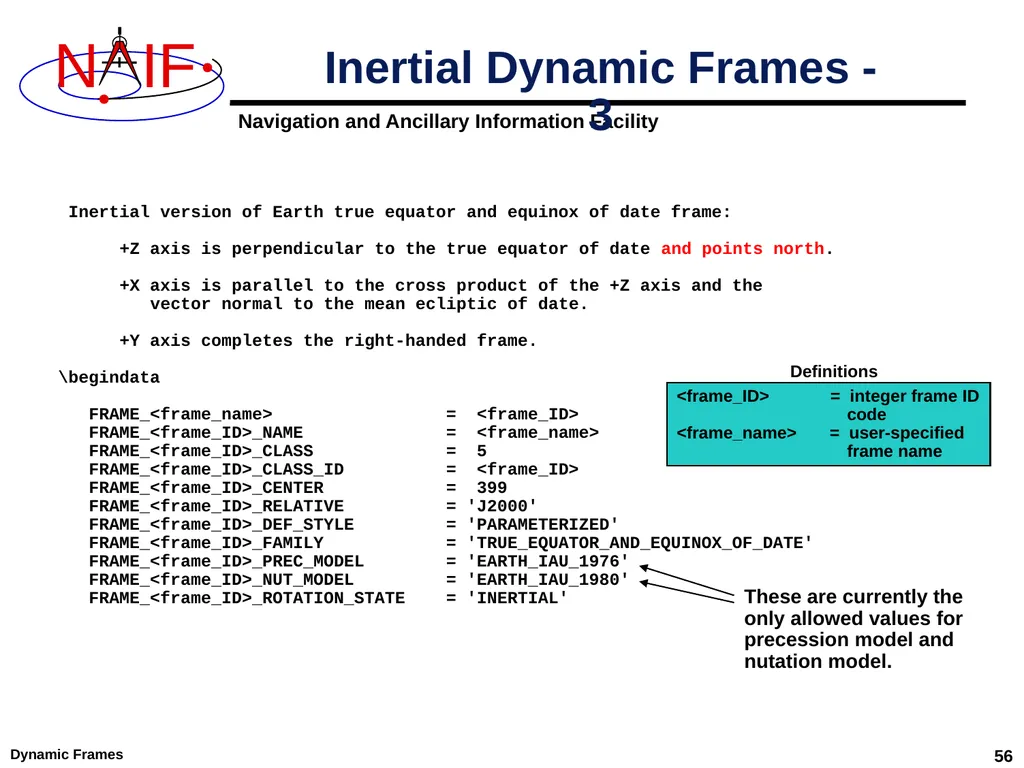
Dynamic Frames 56 Inertial Dynamic Frames - 3 Inertial version of Earth true equator and equinox of date frame:
+Z axis is perpendicular to the true equator of date and points north.
+X axis is parallel to the cross product of the +Z axis and the
vector normal to the mean ecliptic of date.
+Y axis completes the right-handed frame.
\begindata
FRAME_<frame_name> = <frame_ID>
FRAME_<frame_ID>_NAME = <frame_name>
FRAME_<frame_ID>_CLASS = 5
FRAME_<frame_ID>_CLASS_ID = <frame_ID>
FRAME_<frame_ID>_CENTER = 399
FRAME_<frame_ID>_RELATIVE = 'J2000'
FRAME_<frame_ID>_DEF_STYLE = 'PARAMETERIZED'
FRAME_<frame_ID>_FAMILY = 'TRUE_EQUATOR_AND_EQUINOX_OF_DATE'
FRAME_<frame_ID>_PREC_MODEL = 'EARTH_IAU_1976'
FRAME_<frame_ID>_NUT_MODEL = 'EARTH_IAU_1980'
FRAME_<frame_ID>_ROTATION_STATE = 'INERTIAL' <frame_ID> = integer frame ID
code
<frame_name> = user-specified
frame name Definitions These are currently the
only allowed values for
precession model and nutation model.<br>
+Z axis is perpendicular to the true equator of date and points north.
+X axis is parallel to the cross product of the +Z axis and the
vector normal to the mean ecliptic of date.
+Y axis completes the right-handed frame.
\begindata
FRAME_<frame_name> = <frame_ID>
FRAME_<frame_ID>_NAME = <frame_name>
FRAME_<frame_ID>_CLASS = 5
FRAME_<frame_ID>_CLASS_ID = <frame_ID>
FRAME_<frame_ID>_CENTER = 399
FRAME_<frame_ID>_RELATIVE = 'J2000'
FRAME_<frame_ID>_DEF_STYLE = 'PARAMETERIZED'
FRAME_<frame_ID>_FAMILY = 'TRUE_EQUATOR_AND_EQUINOX_OF_DATE'
FRAME_<frame_ID>_PREC_MODEL = 'EARTH_IAU_1976'
FRAME_<frame_ID>_NUT_MODEL = 'EARTH_IAU_1980'
FRAME_<frame_ID>_ROTATION_STATE = 'INERTIAL' <frame_ID> = integer frame ID
code
<frame_name> = user-specified
frame name Definitions These are currently the
only allowed values for
precession model and nutation model.<br>
57
Dynamic Frames 57 Backup Numerical Issues
Limitations<br>
Limitations<br>
58
Dynamic Frames 58 Two-vector frame derivatives may be inaccurate. Let R(t) represent a time-dependent rotation:
If R(t) depends on CK data, dR(t)/dt may be inaccurate because CK rates frequently have low accuracy.
If R(t) depends on velocity vectors, then dR(t)/dt depends on acceleration determined via numerical differentiation. Typically such derivatives suffer loss of accuracy.
However, if velocities are "well-behaved," numerically derived acceleration can be quite good. Example: GSE frame.
If R(t) depends on position vectors, the velocities associated with those vectors by the SPK system may not be mathematically consistent with the positions. This can happen for SPK types with separate polynomials for position and velocity, such as types 3, 8, 9, and 14.
If R(t) depends on aberration-corrected vectors, the associated velocities may be inaccurate due to accuracy limitations of the aberration corrections applied to velocities by the SPK system. Numerical Issues - 1<br>
If R(t) depends on CK data, dR(t)/dt may be inaccurate because CK rates frequently have low accuracy.
If R(t) depends on velocity vectors, then dR(t)/dt depends on acceleration determined via numerical differentiation. Typically such derivatives suffer loss of accuracy.
However, if velocities are "well-behaved," numerically derived acceleration can be quite good. Example: GSE frame.
If R(t) depends on position vectors, the velocities associated with those vectors by the SPK system may not be mathematically consistent with the positions. This can happen for SPK types with separate polynomials for position and velocity, such as types 3, 8, 9, and 14.
If R(t) depends on aberration-corrected vectors, the associated velocities may be inaccurate due to accuracy limitations of the aberration corrections applied to velocities by the SPK system. Numerical Issues - 1<br>
59
Dynamic Frames 59 Recommendations
Avoid using aberration corrections in two-vector frame definitions if accurate velocity transformations are required.
Be aware of the accuracy of the data on which two-vector frames are based. Numerical Issues - 2<br>
Avoid using aberration corrections in two-vector frame definitions if accurate velocity transformations are required.
Be aware of the accuracy of the data on which two-vector frames are based. Numerical Issues - 2<br>
60
Dynamic Frames 60 Simulated recursion:
ANSI Fortran 77 doesn't support recursion, so the SPICE dynamic frame system implements limited, simulated recursion.
Two levels of recursion are supported for selected SPK and Frames System routines.
Users must avoid requesting "deeper" recursion than the SPICE dynamic frame system can support.
When defining dynamic frames:
Choose J2000 as the base frame for two-vector frames.
Except for Euler frames, avoid using dynamic frames as base frames.
Try to avoid choosing a dynamic frame as the frame associated with a velocity or constant vector.
In SPK, CK, or PCK kernels, don't use two-vector frames as the base frame relative to which ephemeris or attitude data are specified.
"Of-date" or Euler frames are OK for this purpose. Limitations - 1<br>
ANSI Fortran 77 doesn't support recursion, so the SPICE dynamic frame system implements limited, simulated recursion.
Two levels of recursion are supported for selected SPK and Frames System routines.
Users must avoid requesting "deeper" recursion than the SPICE dynamic frame system can support.
When defining dynamic frames:
Choose J2000 as the base frame for two-vector frames.
Except for Euler frames, avoid using dynamic frames as base frames.
Try to avoid choosing a dynamic frame as the frame associated with a velocity or constant vector.
In SPK, CK, or PCK kernels, don't use two-vector frames as the base frame relative to which ephemeris or attitude data are specified.
"Of-date" or Euler frames are OK for this purpose. Limitations - 1<br>
61
Dynamic Frames 61 Run-time efficiency:
Dynamic frame evaluation typically requires more computation than is needed for CK- or PCK-based frames.
For example, evaluation of a two-vector frame may involve several SPK calls.
Euler frames are an exception: these are fairly efficient as long as they don't have a base frame that requires a lot of computation to evaluate.
To minimize the performance penalty:
use J2000 as the base frame for two-vector frames.
use the simplest frames possible for association with velocity or constant vectors in two-vector frame definitions.
Prefer non-dynamic frames to dynamic frames and inertial frames to non-inertial frames where there is a choice. Limitations - 2<br>
Dynamic frame evaluation typically requires more computation than is needed for CK- or PCK-based frames.
For example, evaluation of a two-vector frame may involve several SPK calls.
Euler frames are an exception: these are fairly efficient as long as they don't have a base frame that requires a lot of computation to evaluate.
To minimize the performance penalty:
use J2000 as the base frame for two-vector frames.
use the simplest frames possible for association with velocity or constant vectors in two-vector frame definitions.
Prefer non-dynamic frames to dynamic frames and inertial frames to non-inertial frames where there is a choice. Limitations - 2<br>