
APPLIED ENGINEERING TECHNOLOGY NCV (Level 4) TOPIC
KB
Published · 409 slides · 0 views

1 / 1




















Description
APPLIED ENGINEERING TECHNOLOGY NCV (Level 4) TOPIC 01 (Pg. 1) MECHANICAL FUNDAMENTALS OF THE ENGINEERING INDUSTRY Topic Outcomes: Upon successful completion of this topic, you will be able to: Explain the principle of mechanical
Related Topics
Share
Embed code
Download this presentation From Below
"APPLIED ENGINEERING TECHNOLOGY NCV (Level 4) TOPIC" is the property of its rightful owner. Permission is granted to download and print the materials on this website for personal, non-commercial use only, and to display it on your personal computer provided you do not modify the materials and that you retain all copyright notices contained in the materials. By downloading content from our website, you accept the terms of this agreement.
Presentation Transcript
01
APPLIED ENGINEERING TECHNOLOGY
NCV
(Level 4)<br>
NCV
(Level 4)<br>
02
TOPIC 01 (Pg. 1)
MECHANICAL FUNDAMENTALS OF THE ENGINEERING INDUSTRY Topic Outcomes:
Upon successful completion of this topic, you will be able to:
Explain the principle of mechanical engineering.
Explain the operating principles of mechanical components used in the engineering-related design industry.
Explain and perform safety checks on mechanical equipment.
Ensure safety in work practices when working in the vicinity of mechanical equipment.<br>
03
UNIT 1 (Pg. 4)
THE PRINCIPLES OF MECHANICAL ENGINEERING Introduction
In the world of mechanical engineering, friction is an undesired force because friction between parts causes the parts to heat up and wear out faster. Friction can badly damage a material and cause it to wear out quickly.
Friction is a force that causes resistance when two surfaces slide or roll over one another.
Force is an influence that tends to change the motion of a body or produce motion or stress in a stationary body.
Machines have many moving parts that are constantly rubbing against each other, when this happen friction occurs.<br>
04
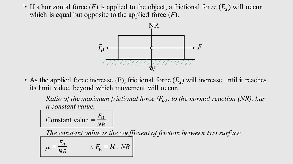
Think of a heavy box lying on a table. If you try to drag the box across the table and it is too heavy to move, this is because of friction. The friction between the box and the table resists movement. When the force is increased, it will eventually be great enough to overcome the friction and the box will move. When this happens the force that you apply to the box is equal to the force of the resistance to motion.
A microscopic view of these surfaces in relative motion indicates that each surface contains tiny, jagged asperities (rough and uneven surfaces), no matter how closely these surfaces are machined. Friction occurs because the surfaces in contact are not smooth.
The negative results of friction are:
Wear on mating rubbing parts,
Generation of heat which is wasteful,
Energy losses.<br>
05
Motion in Engineering Design (Pg. 5)
Motion is the action or process of moving or being moved. Motion occurs when an object changes its position over time.
When there is a change in the distance between two object, we have motion.
In mechanical engineering, energy is used to create motion. e.g. the combustion of petrol in an engine supplies the energy to drive the pistons.
# State of Motion
Motion or movement means the change in position of an object.
When there is a change in the distance between two objects, we have motion.
The resistance to a change in motion is called the inertia of an object and the amount of inertia depends on the mass of the object.<br>
06
Three Laws of Motion
Newton’s first law of motion states: (Pg. 5)
If a body is at rest or moving at a constant speed in a straight line, it will remain at rest or keep moving in a straight line at constant speed unless it is acted on by a force.
In other words, objects will keep on moving in the same direction forever if no forces are applied to them. If there is no net force acting on an object, then the object will remain at rest.
This is normally taken as the definition of inertia.
The tendency of a body to keep its state of rest or uniform motion is termed its inertia. Inertia is dependent on the mass of the body.
The mass of a body is defined as the amount of matter which it contains.<br>
07
Newton's Second law of motion (Pg. 6)
If a force acts upon a body of a certain mass, then it produces a change in velocity of that body.
If external force is apply, the velocity will change because of the force.
For external applied force, the change in velocity depend on the mass of the object. The change of velocity is called acceleration.
A force will cause change in velocity and likewise, change in velocity will generate a force.<br>
08
Newton's Third law of motion (Pg. 6)
For every action there is an equal and opposite reaction.
If object A exerts a force on object B, then object B also exerts an equal force on object B.
Normal reaction (Pg. 6)
Normal reaction is the force without acceleration, i.e. when object is not moving.
When a body lies on the surface of the earth, it is under the influence of gravity. The force on the body due to gravity causes it to exert a force on the ground and normal reaction acts in the opposite direction causing the resultant force on the body to be zero.<br>
09
Resistance to motion (Pg. 6)
Inertia is the resistance of any physical object to any change in its velocity. This includes changes to the object‘s speed, or direction of motion.
Thus the object will continue moving at its current velocity until some force cause its speed or direction change.
The magnitude of the frictional force on clean and dry surfaces depends on:
The normal reaction between the surfaces in contact, which depends on the load pressing the two surfaces together.
The materials of which the two surfaces are made.
The surface finish of the surfaces in contact, i.e. either rough, smooth or polished.<br>
10
The effect of surface on friction (Pg. 8)
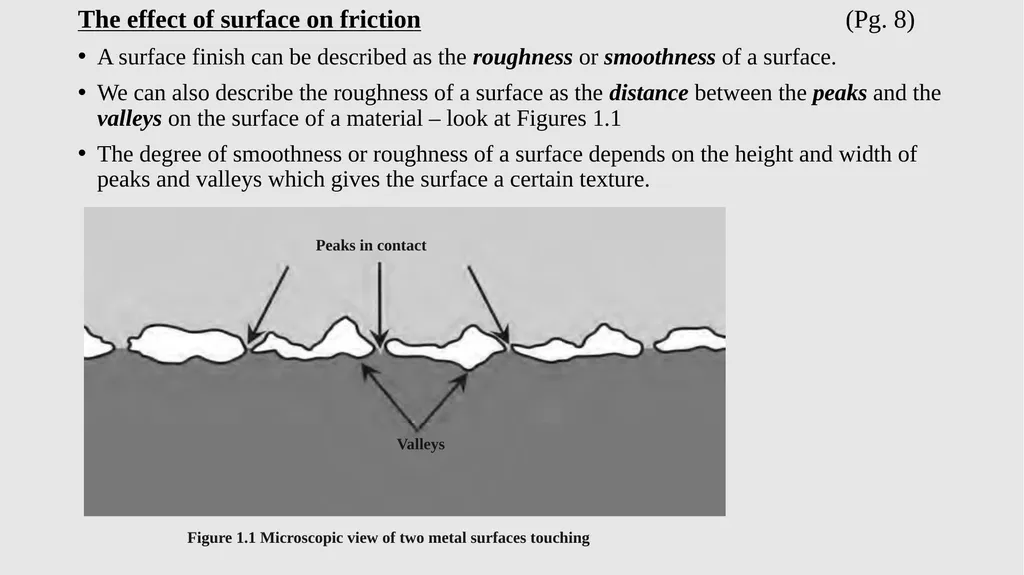
A surface finish can be described as the roughness or smoothness of a surface.
We can also describe the roughness of a surface as the distance between the peaks and the valleys on the surface of a material – look at Figures 1.1
The degree of smoothness or roughness of a surface depends on the height and width of peaks and valleys which gives the surface a certain texture.<br>
11
The rougher a surface is, the more quickly it wears out because it creates more friction. Roughness is not advantageous when it comes to mechanical components because they are often subject to high friction. When surfaces are too rough and they rub against each other, the peaks break off and the material slowly wears away.
The roughness or smoothness can be achieved by a machining process or by applying a coating or a layer to the material. In most cases the designer is responsible for choosing the surface finish that will work most effectively.
Surface finishes specification are applied for the following reasons:
To encourage sliding motion
To reduce friction between two workpieces in an assembly
To protect material from moisture, fungus and mould
To make the material stronger and to increase surface hardness.<br>
12
The method of assessing surface roughness is either by:
Sophisticated Stylus Type Equipment.
Pocket size instruments with digital readouts.
Surface roughness comparison specimens (or surface texture plate, sometimes referred to as a scratch block).<br>
Sophisticated Stylus Type Equipment.
Pocket size instruments with digital readouts.
Surface roughness comparison specimens (or surface texture plate, sometimes referred to as a scratch block).<br>
13
Surface texture plate are used to give machine operators an idea of the relation of the feel and appearance of common machined surfaces to their numerical roughness value.
By visual examination and by scratching the surface with a finger nail, a comparison can be made between the specimen and the workpiece surface.
The texture of surface may be regular or irregular in character and may lie in a particular direction or be non-directional.<br>
By visual examination and by scratching the surface with a finger nail, a comparison can be made between the specimen and the workpiece surface.
The texture of surface may be regular or irregular in character and may lie in a particular direction or be non-directional.<br>
14
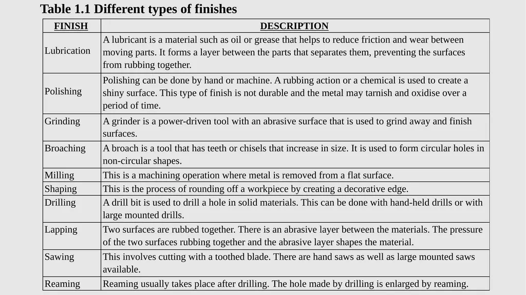
Table 1.1 Different types of finishes<br>
15
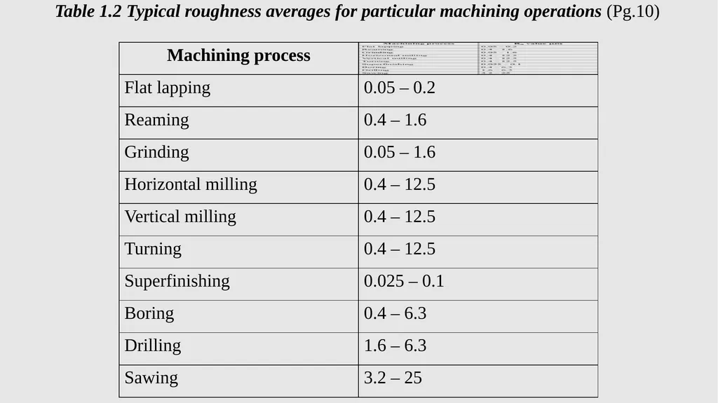
Table 1.2 Typical roughness averages for particular machining operations (Pg.10)<br>
16
Measuring surface finish (Pg. 10)
Two ways to measure or gauge surface finish
A surface texture plate
This method is inexpensive and is subjected to the perceptions of the machinist.
It is a subjective method.
Machinists may use their fingers and eyes to compare the workpiece to a representative sample.
The disadvantage of this method is that no machinist will have the same feel of the surface finish.<br>
17
A surface tracing machine
This machine automatically pull a stylus across the surface and records roughness and waviness.
Parts of instruments: stylus with a small tip, a gauge or transducer, a traverse datum and a processor.
The surface is measured by moving the stylus across the surface.
The gauge needs to pass over the surface in a straight line so that the stylus tip follows the surface under test for correct data collection.<br>
18
Reducing friction (Pg. 11)
The importance of reducing friction is:
To make surface smoother. Lubrication is another way to make a surface smoother and reduce wear.
To make the object more streamlined.
To reduce the force acting on the surface.
To reduce the contact between the surface.
When the frictional force is overcome and motion occurs, work is done against friction and heat is generated. This heat must be removed from the surfaces as quickly as possible.<br>
19
Friction only occurs when two surfaces are in relative motion, such as when a crankshaft is rotating in a journal bearing. Another factor that must be overcome is wear.
The rate of wear between the surface depends on load, surface finish and speed of motion. The higher the speed, the faster the rate of wear.
No wear or friction can take place if the surfaces are kept apart by introducing a lubricant.
Lubricants are either solid, liquid or gaseous.<br>
The rate of wear between the surface depends on load, surface finish and speed of motion. The higher the speed, the faster the rate of wear.
No wear or friction can take place if the surfaces are kept apart by introducing a lubricant.
Lubricants are either solid, liquid or gaseous.<br>
20
Kinetic friction
Kinetic friction is a friction between two objects that are already moving.
Once the objects have already started moving, kinetic friction take over. This friction occurs when motion took place.
This is the friction that exist between two objects moving relative to each other.
Kinetic friction resists the motion of an object sliding across a surface. Note that kinetic friction (fk) is also known as sliding friction and is related to movement.
Kinetic friction isn't as strong as static friction, and so its easier to keep the object moving.<br>
21
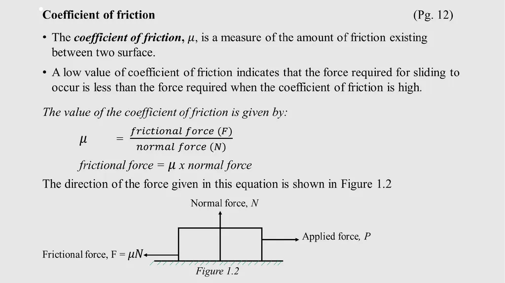
Coefficient of friction (continued)
The coefficient of friction is the ratio of a force to a force, and hence has no units.
For every combination of two surfaces, there is a coefficient of friction.
Table 1.2 on Pg. 14 shows the average static and kinetic coefficient of sliding friction for various pairs of materials.<br>
The coefficient of friction is the ratio of a force to a force, and hence has no units.
For every combination of two surfaces, there is a coefficient of friction.
Table 1.2 on Pg. 14 shows the average static and kinetic coefficient of sliding friction for various pairs of materials.<br>
22
The relationship between mass, friction and the force required for motion
The main cause of friction in mechanical systems are: (Pg. 14)
The surface finish of the components in contact (the rougher the surface, the harder it is to move or slide the object),
The weight or force pressing the surfaces together (the bigger the weight or force in contact with another object, the harder it is to create motion between the two object),
The molecular attraction, adhesion and cohesion, between the materials in contact (Adhesion is the force of attraction between the contact regions of surfaces which are always microscopically irregular resulting in friction).<br>
23
Weight or force pressing surfaces together (Pg. 14)
In engineering, weight indicates the strength of the gravitational pull on an object. This is literally how heavy an object is. Weight is a force measured in newtons whereas mass is measured in kilograms. There is a relationship between mass and weight: the weight of an object is proportional to its mass.
When we speak of an object’s mass, we refer to the tendency of an object to have a stable velocity unless the object is driven by an external force. We speak of weight when there is a force created within the object’s mass which is driven by gravity. To calculate an object’s weight, you need the object’s mass as the weight of an object can vary, even on Earth. The force of the gravitational pull of the Earth is 9.81.<br>
24
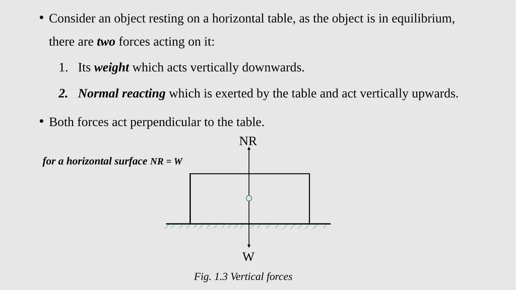
Consider an object resting on a horizontal table, as the object is in equilibrium, there are two forces acting on it:
Its weight which acts vertically downwards.
Normal reacting which is exerted by the table and act vertically upwards.
Both forces act perpendicular to the table.
NR
for a horizontal surface NR = W
W
Fig. 1.3 Vertical forces<br>
Its weight which acts vertically downwards.
Normal reacting which is exerted by the table and act vertically upwards.
Both forces act perpendicular to the table.
NR
for a horizontal surface NR = W
W
Fig. 1.3 Vertical forces<br>
25
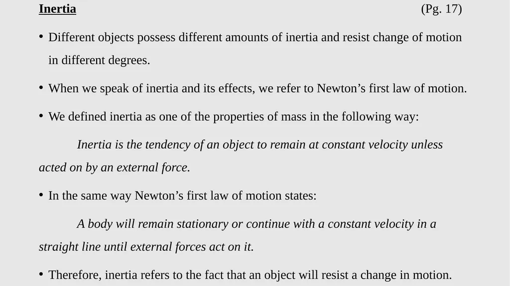
Inertia (Pg. 17)
Different objects possess different amounts of inertia and resist change of motion in different degrees.
When we speak of inertia and its effects, we refer to Newton’s first law of motion.
We defined inertia as one of the properties of mass in the following way:
Inertia is the tendency of an object to remain at constant velocity unless acted on by an external force.
In the same way Newton’s first law of motion states:
A body will remain stationary or continue with a constant velocity in a straight line until external forces act on it.
Therefore, inertia refers to the fact that an object will resist a change in motion.<br>
26
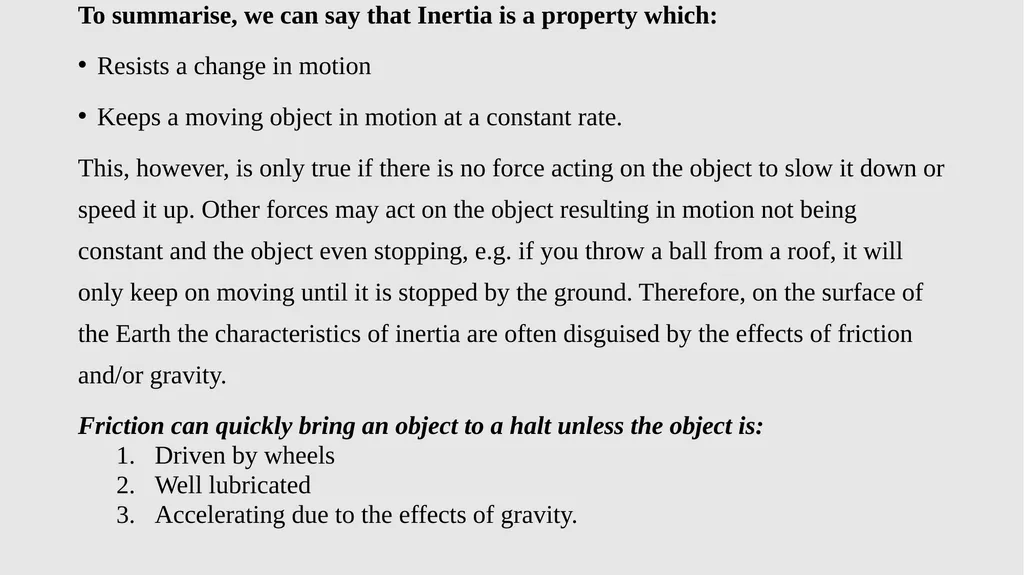
To summarise, we can say that Inertia is a property which:
Resists a change in motion
Keeps a moving object in motion at a constant rate.
This, however, is only true if there is no force acting on the object to slow it down or speed it up. Other forces may act on the object resulting in motion not being constant and the object even stopping, e.g. if you throw a ball from a roof, it will only keep on moving until it is stopped by the ground. Therefore, on the surface of the Earth the characteristics of inertia are often disguised by the effects of friction and/or gravity.
Friction can quickly bring an object to a halt unless the object is:
Driven by wheels
Well lubricated
Accelerating due to the effects of gravity.<br>
27
UNIT 2 (Pg. 20) The operating principles of mechanical components used in the engineering-related design industry
Introduction
Where there is a shaft that turns, it must be supported, and such a support is called a bearing. The support must be firmly fixed and must allow the shaft to turn or slide freely. Oil or grease is supplied to reduce friction. there are bearings in nearly all machines and if one bearing in a machine fails, the whole machine stop.<br>
28
Plain Bearings (Pg. 21)
Plain bearings are also referred to as sliding bearings which in turn are subdivided into journal bearing and thrust bearings.
Bearing application together with lubrication is the art of reducing friction, wear and heating of machine parts in order to obtain high mechanical efficiencies.
Plain bearing reduce friction between two parts of a mechanism, one of which is stationary and the other rotating.
Types of plain bearing:
Linear bearing b) Journal bearing c) Thrust bearing
Plain bearing can be Hydrostatically or Hydrodynamically lubricated or operated dry.<br>
29
The coefficient of friction for plain bearings relate to:
The type of bearing,
The speed of rotation,
The load,
The amount and viscosity of the lubrication,
The friction of the sleeve.
Plain bearing and sleeve bearing (journal bearing) are used to:
Limit, guide or reduce friction in rotary or linear applications.
The metals used to made plain and sleeve bearings are:
Brass b) Different Bronzes c) White metal
Alloys of aluminium.<br>
30
Some of plain and sleeve bearings are designed to operate without oil or grease and they are called self-lubricating bearings.
Some product are designed for extreme environments and can withstand high or low temperatures.
Others are suitable for hazardous environments with high levels of shock and vibration.
Advantages of plain bearing:
They are not expensive to manufacture,
They are silent in operation,
They are strong,
They are easily replaced when worn.<br>
31
Disadvantages of plain bearing:
They need to be lubricated constantly,
Start-up torque is high,
They can be damaged easily by dirt in the oil or grease,
They create more friction than ball or roller bearing.<br>
They need to be lubricated constantly,
Start-up torque is high,
They can be damaged easily by dirt in the oil or grease,
They create more friction than ball or roller bearing.<br>
32
Class and applications of plain bearings (Pg. 22)
There are three classes of plain bearings
Class 1 bearings are lubricated from an outside source, e.g. by means of a pump or oil bath. They are made from Babbitts, which is an alloy of copper and antimony.
Class 2 bearings have internal lubrication. e.g. oilyte bearings are impregnated with a lubricant during manufacture. They are made from Sintering bronze, in which bronze in the powder form is mixed with lubricant.
Class 3 bearings require no lubrication at all. They are made from plastic or polytetrafluorethylene (PTFE).<br>
33
Applications for plain and sleeve bearings include:
Automotive equipment
Agriculture
Food processing machinery
packaging equipment
Home appliance
Office machines.<br>
Automotive equipment
Agriculture
Food processing machinery
packaging equipment
Home appliance
Office machines.<br>
34
Bearing lubrication (Pg. 22)
Three ways to lubricate bearings
Hydrostatic lubrication
Hydrodynamic lubrication
Boundary lubrication.
1. Hydrostatic lubrication
Sliding friction is significantly reduced by an addition of a lubricant between the rubbing surfaces.
Bearings are lubricated by oils constantly supplied in sufficient amounts to the bearings surface.
Lubricated friction is characterized by the presence of a thin film of the pressurized lubricant (squeeze film) between the surfaces of the bearing and journal.<br>
35
Advantages of hydrostatic lubrication:
It can accommodate heavy loads at low speeds.
It does not depend on relative motion to maintain the lubrication film.
Another advantage of this lubrication system is low deflection in certain load ranges.
Disadvantage of hydrostatic lubrication:
High cost and complexity.
Application of hydrostatic lubrication:
For high-precision machine tools.<br>
36
2. Hydrodynamic lubrication
High rotation speed at relatively low bearing loads results in hydrodynamic friction, which is characterized by stable squeeze film between the rubbing surface.
No contact between the surfaces occurs in hydrodynamic lubrication.
The squeeze film keeps the surfaces of the bearing and the shaft apart due to the force called hydrodynamic lift generated by the lubricant squeezed through the convergent gap between the acentric journal and bearing.
The lubrication action improves as speed increases, which goes hand-in-hand with an increase in loads experienced as the speed increases.
Disadvantage of hydrodynamics is an inability to carry heavy loads at low speed and appreciable wear when there are frequent stop or starts, or motion reversal.<br>
37
A hydrodynamic film occurs when there is sufficient lubricant between the two contact surfaces at the point of loading to form a fluid wedge that separates the sliding surface.
In this case, the lubricated components do not touch each other, reducing friction and wear.
3. Boundary lubrication
At high loads or low speeds, the pressure of the hydrodynamic film cannot prevent metal-to-metal contact.
The opposing surfaces partly ride on an oil film and partly rub together as surface high point come in contact.
Application of boundary lubrication:
It is found with slow-moving loads.
Hinge bearings in aircraft landing gear.<br>
38
Solid Sleeve Bearings (Pg. 24)
Solid sleeve bearings facilitate linear movement between two parts.
Sleeve bearing consist of a metal, plastic or fiberreinforced composite sleeves that reduce vibrations and noise by absorbing friction between two moving parts using a sliding motion.
Sleeve bearing offer several advantages, including lower cost, less maintenance, greatly reduce noise at low speed and easier installation. Disadvantage being that the bearing can not be repaired when worn.
Sleeve bearing performance is also marked by a higher load capacity, especially shock load resistance due to their greater contact zone.
Sleeve bearing can be made from bronze, steel or stainless steel, brass and plastic.
Three common designs of sleeve bearing:
a) Flanged bearing b) Cylindrical bearing c) Lined bearing<br>
39
Sleeve bearings are made of a single bearing surface, with no rolling parts.
Sleeve bearings are used to constrain, guide or reduce friction in rotary or linear applications.
Applications:
Where the velocity and pressure are moderate and where little wear is expected.
Small end of connecting rods,
Belt idler pulleys an shafts,
loose pullets on shaft,
Starter motors and generations.
Internal combustion engine.<br>
40
Split Bearings (Pg. 25)
They are used in industrial machinery where larger diameters are required, such as crankshaft bearing.
They are made in such a way that they consist of two parts.
The advantage of split bearings is that they can be re-metalled and used again or scrapped for use elsewhere after removal.
Applications/use:
Where they make it easier to fit and remove shafts or replace bearings.
Big end bearings in reciprocating engines.
Split housings on power transmission shaft.
Pinion gear shafts.
Mine winders.<br>
41
Footstep Bearings (vertical thrust bearing) (Pg. 26)
Footstep bearing consists of a cast iron black, into which a bush consisting of a collar at the top is fitted. The shaft rests on pad/disc.
The pad is prevented from rotating by a pin.
The collar of the bush is made hollow to serve as an oil sump for lubrication of the bearing.
The collar is subjected to heavy thrust loads along the axis of the shaft.
Footstep bearing can only be place along the bottom of the shaft.
Footstep bearings are designed to provide support to a vertical shaft or spindle which revolve in a vertical position.<br>
42
Thrust Bearings (Pg. 26)
Thrust bearing permit rotation between parts, and are design to support a predominantly axial load.
The main function of a thrust bearing is to resist any axial force applied to the rotor and maintain its position.
Disadvantage:
Higher weight,
More friction,
Susceptible to corrosion,
Produce more noise than plastic bearing.
Thrust bearing support loads that are parallel to the bearing axis, so they are designed to withstand forces in the same direction as the shaft (axial loads).<br>
43
Thrust bearings are used in applications that use little axial load, where a ring supports ball bearings.
Thrust bearings are used in higher speed applications that require oil lubrication, e.g. Automotive and Aerospace industries.
Types of thrust bearing:
Single-collar thrust bearing
Single-collar thrust bearing support and reduce axial loads or movement of the shaft in the direction of its axis. (e.g. washer).
Multi-collar thrust bearing
These take up axial loads in both directions and distribute the thrust loads evenly through the number of collars.<br>
44
Guide bearings (machine slide) (Pg. 27)
They are use to support movement of machine components along a linear path. (e.g. the cross slide of a centre lathe and the table movement of a milling machine).
A plain bearing used to give a machine element in its lengthwise motion, usually without rotation of the element.
They are designed to enable rotational or linear movement in a device.
Unlike ball bearings, linear bearings can run on various kinds of shafting from hardened to stainless steel.
Advantages of guide bearing: They are generally less rigid, do not require seals, bear wider temperature ranges, and are simple to integrate into existing system.<br>
45
Bearing materials (Pg. 27)
Plain bearings and sleeve bearings use several surface materials:
Sintered bronze
Can be used at high speed with light loading and offer good corrosion-resistance.
It is often used in applications where lubrication is difficult or inconvenient.
They are used in domestic appliance, starter motors and car parts.
Polytetrafluorethylene (PTFE)
PTFE is resistant to most chemicals,
It has low coefficient of friction,
It has poor thermal conductivity and high coefficient of expansion,
It is used as a static bearing pads for bridge expansion joints.<br>
46
Nylon
Operate under light to medium load,
It is tough and abrasion-resistant,
It resist chemical attack,
It is non-toxic,
It is used in bushes, thread guides, rollers and slides in textile machinery.
Cast iron
For machine tool parts e.g. milling machine slide, and lathe beds.<br>
Operate under light to medium load,
It is tough and abrasion-resistant,
It resist chemical attack,
It is non-toxic,
It is used in bushes, thread guides, rollers and slides in textile machinery.
Cast iron
For machine tool parts e.g. milling machine slide, and lathe beds.<br>
47
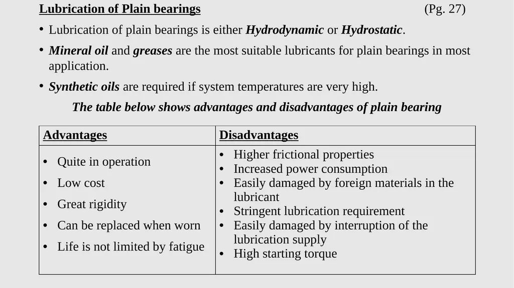
Lubrication of Plain bearings (Pg. 27)
Lubrication of plain bearings is either Hydrodynamic or Hydrostatic.
Mineral oil and greases are the most suitable lubricants for plain bearings in most application.
Synthetic oils are required if system temperatures are very high.
The table below shows advantages and disadvantages of plain bearing<br>
48
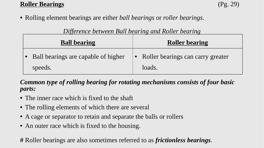
Roller Bearings (Pg. 29)
Rolling element bearings are either ball bearings or roller bearings.
Difference between Ball bearing and Roller bearing
Common type of rolling bearing for rotating mechanisms consists of four basic parts:
The inner race which is fixed to the shaft
The rolling elements of which there are several
A cage or separator to retain and separate the balls or rollers
An outer race which is fixed to the housing.
# Roller bearings are also sometimes referred to as frictionless bearings.<br>
49
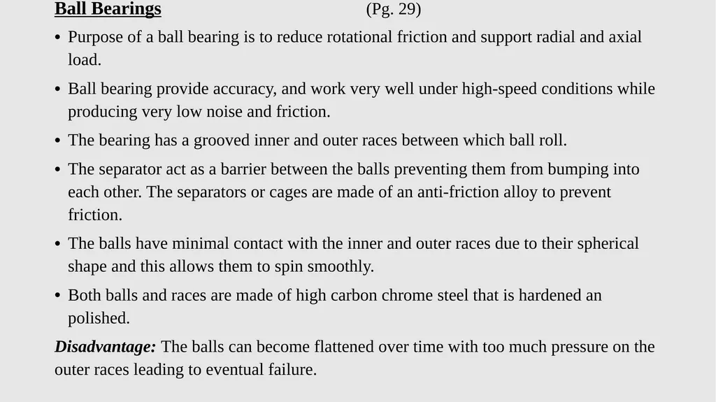
Ball Bearings (Pg. 29)
Purpose of a ball bearing is to reduce rotational friction and support radial and axial load.
Ball bearing provide accuracy, and work very well under high-speed conditions while producing very low noise and friction.
The bearing has a grooved inner and outer races between which ball roll.
The separator act as a barrier between the balls preventing them from bumping into each other. The separators or cages are made of an anti-friction alloy to prevent friction.
The balls have minimal contact with the inner and outer races due to their spherical shape and this allows them to spin smoothly.
Both balls and races are made of high carbon chrome steel that is hardened an polished.
Disadvantage: The balls can become flattened over time with too much pressure on the outer races leading to eventual failure.<br>
50
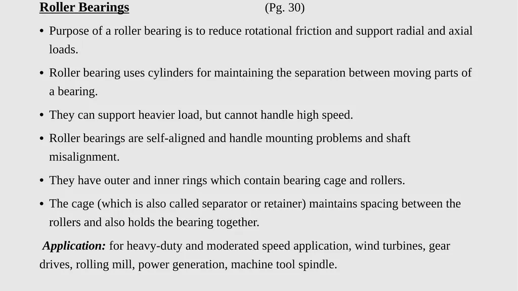
Roller Bearings (Pg. 30)
Purpose of a roller bearing is to reduce rotational friction and support radial and axial loads.
Roller bearing uses cylinders for maintaining the separation between moving parts of a bearing.
They can support heavier load, but cannot handle high speed.
Roller bearings are self-aligned and handle mounting problems and shaft misalignment.
They have outer and inner rings which contain bearing cage and rollers.
The cage (which is also called separator or retainer) maintains spacing between the rollers and also holds the bearing together.
Application: for heavy-duty and moderated speed application, wind turbines, gear drives, rolling mill, power generation, machine tool spindle.<br>
51
Loads on bearings (Pg. 31)
Three different bearing loads
Radial load – it is the load that occurs at right angles to the horizontal axis of the shaft.
Thrust or Axial load – it is the load that occurs in a parallel direction to the shaft.
Angular load – it is the combination of radial and thrust load.<br>
Three different bearing loads
Radial load – it is the load that occurs at right angles to the horizontal axis of the shaft.
Thrust or Axial load – it is the load that occurs in a parallel direction to the shaft.
Angular load – it is the combination of radial and thrust load.<br>
52
Types of Ball Bearing
Single-row deep-groove ball bearings (Pg. 31)
It is designed to carry radial loads and can also support small axial loads in both directions of the shaft axis.
They have a deep groove machined in the outer and inner rings in which a single row of ball rolling elements roll.
It cannot tolerate shaft misalignment and only 2 to 10 minutes of arc misalignment can be accommodated by the bearing.
Application: Household appliances, small to medium-size electric motors and pumps, automotive gearbox, wheels and conveyor idlers.<br>
53
Double-row deep-groove ball bearings (Pg. 32)
It is designed to carry higher radial load and lesser axial loads in both directions.
The disadvantage is that the operating speed is reduced much considerably.
It cannot tolerate shaft misalignment and only 2 to 10 minutes of arc misalignment can be accommodated by the bearing.
Application: belt idler pulleys.
Self-aligning ball bearings (Pg. 32)
The outer ring has a surface-ground curvature to allow for misalignment while the inner ring has two grooved raceways. The balls retained in the cage form a unit with the inner ring and can align itself spherically within the outer ring.
It is designed to carry higher radial load and little axial load in both directions.
The bearing is not affected by misalignment of the shaft and housing.<br>
54
Single-direction thrust ball bearings (Pg. 32)
Thrust ball bearings have only a single row of balls.
They carry thrust/axial loads in one direction only.
These bearings can handle little or no radial load.
Double-direction thrust ball bearings (Pg. 33)
This type of thrust ball bearing support axial loads in both directions and have a row of balls on either side of a disc.
Thrust ball bearings with flat washers do not permit any misalignment between the shaft and housing.<br>
55
Types of Roller Bearing
Needle roller bearings (Pg. 33)
They are used to support shafts in slow to medium speed drives.
The overall diameter of the bearing is small and may have 50 needles roller which are extremely long and thin.
Application: connecting rods of internal combustion engines.
Single-row cylindrical roller bearings (Pg. 34)
They use cylinders as opposed to the balls in ball bearings.
They are suitable for high speed rotation.
They carry much higher radial loads and high rigidity than ball bearings and allow no axial loads.
Application: heavy industrial gearbox, large pumps, steel mills, hoists, power generation.<br>
56
Spherical roller bearings (Pg. 34)
Spherical roller bearings consist of two rows of barrel-shaped rollers running in two raceways. They are mounted in pairs inside the bearing housing and are faced in opposite directions.
These are used in heavy industrial and mining machines, and support heavy radial and axial loads.
They are capable of coping with misalignment error associated with vibrating machinery. (2.5° errors of alignment).
Application: spherical roller bearings are used in car hubs,<br>
57
Tapered roller bearings (Pg. 35)
Tapered roller bearing includes an outer ring, inner ring, a plurality of tapered roller, and a cage for the tapered rollers.
Suitable for heavy combined axial and radial load and can operate well at high speed.
Tapered roller bearings have high load capacities and high rigidity.
Axial loads are supported in one direction only.
It cannot tolerate shaft misalignment and misalignment is limited to a few minutes of arc.
Application: automotive wheel bearings, industrial gearboxes, axle systems and engine, aircraft fuel pump, rolling mills.<br>
58
Pumps (Pg. 35)
The mechanical device or arrangement by which water is caused to flow at increased pressure is known as a pump.
Pumps are used to convert mechanical power into fluid power or vice versa.
Pumps are used to move liquid through a piping system and to rise the pressure of the liquid. Pumps are also used to move or raise fluids.
Pumps are classified into two major groups:
Positive displacement pump – Reciprocating pump and Rotary pump
Non-positive displacement pump – Centrifugal pump, Turbine pump, Propeller pump, Jet pump, Air lift pump.<br>
59
Types of pump (Pg. 36)
Reciprocating Pumps
Reciprocating pump is a positive displacement pump.
Reciprocating pump is a hydraulic machine which converts the mechanical energy into hydraulic energy.
Reciprocating pump move the fluid using one or more oscillating pistons, plungers or diaphragms, while valves restrict fluid motion to the desired direction.
Pumps in this category are simple, with one cylinder or more. They can be either single-acting with suction during one direction of the piston motion and discharge on the other or double-acting with suction and discharge in both directions.
Reciprocating pumps are more suitable for low volumes of at high pressures.<br>
60
Operation of Reciprocating pumps
In this type of pump, a piston or a plunger moves inside a close cylinder. On the intake stroke, the suction valve (non-return valve) remain open and allows water to come into the cylinder. The delivery valve (non-return valve) remains close during intake stroke.
On the discharge stroke, the suction valve is closed and water is forced in delivery pipe through delivery valve which opens during discharge stroke. The pressure in the cylinder triggers the valves at the suction and discharge points.
The suction and delivery valves are non-return valves, which allow the water to flow in one direction only.
The suction valve allows water from the suction pipe to the cylinder and where the delivery valve allows water from the cylinder to the delivery pipe only.<br>
61
Types of reciprocating pump
Single-acting reciprocating pump
This has one suction valve and one discharge valve. when the piston is moved backward or upward, suction happens and when it moves forward or downward, the delivery valve opens up to discharge the liquid.
Double-acting reciprocating pump
There are two suction and two delivery valves. When the piston is moved forward or backward, with each stroke, both suction and expulsion happen simultaneously. Thus it requires two inflow pipes and two outflow pipes.
Application of reciprocating pumps:
Salt water disposal, well services, descaling, hydraulic fracturing, and oil and gas pipelines.<br>
62
Advantages of reciprocating pumps:
High pressure is obtained at the outlet.
The priming process is not needed in this pump.
Provides high suction lift.
It is also use for air.
Disadvantages of reciprocating pump:
It requires high maintenance.
Low flow rate.
They are heavy and bulky in size.<br>
High pressure is obtained at the outlet.
The priming process is not needed in this pump.
Provides high suction lift.
It is also use for air.
Disadvantages of reciprocating pump:
It requires high maintenance.
Low flow rate.
They are heavy and bulky in size.<br>
63
Pistonless Pumps (Pg. 39)
2.1 Diaphragm pumps
Diaphragm pump use a flexible diaphragm to displace liquid.
The purpose of diaphragm is to separate two halves of the pump body, forming a seal.
The diaphragm creates a vacuum as the rod moves upwards, thus allowing liquid to enter the body through the inlet valve.
As the rod moves downwards, the inlet valve is forced to closed and the outlet valve to open allowing liquid to passes through.
Application of diaphragm pump:
Petrol pump found in vehicles.<br>
64
Rotary pumps (Pg. 40)
3.1 Gear pumps
Gear pump consist of two meshed gears that rotate in a closely fitted casing.
The meshed gears revolves in opposite direction within a casing.
When the gear teeth mesh with the teeth of the other gear, the space between the teeth is reduced, and the entrapped liquid is forced out the pump discharge pipe. The tooth spaces trap fluid and force it around the outer periphery.
The fluid does not travel back on the meshed part, because the teeth mesh closely in the centre.
As the gears revolve and the teeth disengage, the space again opens on the suction side of the pump, trapping new quantities of liquid and carrying it around the pump case to the discharge.
There are no valves in the gear pump to cause friction losses.
Gear pump see wide use in car engine oil pump.<br>
65
3.2 Sliding-vane pumps (Pg. 40)
Vane pumps are self-priming and deliver a constant, smooth flow regardless of pressure variations.
A vane pump is a positive-displacement pump that consists of vanes mounted to a rotor that rotates inside of a cavity.
The rotor is pressed onto the oil-pump shaft and is fixed to the shaft by a pin.
The vanes are held against the pump-body wall by centrifugal force while the pump is operating.
Rotary vane pumps are a common type of vacuum pump, with two stage pumps.
Vane pumps are the most common type of pump used on agricultural vacuum tanker.<br>
66
Centrifugal pumps (Pg. 41)
The hydraulic machine which converts the mechanical energy into hydraulic energy is called Pumps.
The hydraulic energy is in the form of pressure energy, if the mechanical energy is converted into pressure energy by means of a centrifugal force acting on the fluid, hydraulic machine is called a Centrifugal pump.
A centrifugal pump is not a positive displacement pump, therefore a pre-determined amount of liquid cannot be delivered consistently.
Centrifugal pump parts:
1) Impeller, 2) Casing, 3) Suction pipe with foot valve and Strainer,
4) Delivery pipe.<br>
67
Impeller
An impeller is a rotating component of a centrifugal pump which transfers energy from the motor that drives the pump to the fluid being pumped by accelerating the fluid outwards from the center of rotation.
The impeller has vanes or blades which direct the flow of the fluid in the pump.
Types of impeller shapes:
Open impeller – it is used for liquids containing some solids, e.g sewerage or drainage fluids.
Semi-open impeller – suitable for fibrous materials and sediment.
An enclosed or shrouded impeller – used mainly for the pumping of liquids.
Casing
The casing that receives the fluid being pumped by the impeller, slow down the fluid's rate of flow. A volute is a curved funnel that increases in area as it approaches the discharge port.<br>
68
The expanding chamber or volute in the casing, collect the water from the wheel, and has a varying radial section proportioned to the quantity of water passing through it in a given time.
Function of the volute is to gradually reduce the velocity of the water after it has left the wheel, and so convert part of its kinetic energy to pressure energy.
Suction pipe with a foot valve and Strainer
A pipe whose one end is connected to the inlet of the pump and another end dips into the water in a sump is known as a suction pipe.
A foot valve is found at the end of a pipeline in a suction lift application. They function as a check valve, but they also have a strainer affixed to their open end.
Delivery pipe
A pipe whose one end is connected to the outlet of the pump and other ends delivers the water at a required height is known as a Delivery pipe.<br>
69
Operations of Centrifugal pump
The centrifugal pump acts as a reversed of an inward radial flow reaction turbine.
The flow in a centrifugal pump is in the radial outward directions.
The centrifugal pump works on the principle of forced vortex flow, when a certain mass of liquid is rotated by an external torque, the rise in pressure head of the rotating liquid takes place.
At the outlet of the impeller, the rise in pressure head will be more and the liquid will be discharged at the outlet with a high-pressure head.
Due to this high-pressure head, the liquid can be lifted to a high level.<br>
70
Single-stage centrifugal pumps
Single-stage centrifugal pump consisting of one impeller, and are perfect for huge flow rate as well as low-pressure fixing.
Multi-stage centrifugal pumps
The multi-stage pump can be built with two or three impellers which are connected in series to provide a high discharge pressure.
The pump casing is usually longer and discharge nozzles are vertical orientation.
Water enters the pump and then passes through the multiple impellers in a series, going from left to right. From there, water passes from the volute that surrounds the volute of one impeller to the suction of the next impeller.
These pumps are used for high head service.<br>
71
Application of Centrifugal pump:
Centrifugal pumps are use in buildings for pumping the general water supply.
For pumping sewage and slurries.
They are also used in fire protection systems.
Beverage industry: used to transfer dairy products such as milk, buttermilk, etc.
Oil energy – pumping crude oil, slurry, mud.<br>
Centrifugal pumps are use in buildings for pumping the general water supply.
For pumping sewage and slurries.
They are also used in fire protection systems.
Beverage industry: used to transfer dairy products such as milk, buttermilk, etc.
Oil energy – pumping crude oil, slurry, mud.<br>
72
Advantages of centrifugal pump
Their aforementioned simplicity.
They don’t require any valves or moving parts.
They rotate at high speed and require minimum maintenance.
Their output is very steady and consistent.
They are very small.
Disadvantages of centrifugal pump
They use rotation instead of suction, therefore have no suction power.
They must be put underwater, or primed before it will move water.
Priming is a process in which the suction pipe, casing, delivery valve, which is filled completely with liquid to be raised from an outside source before starting the motor.<br>
73
Terminology related to pump technology (Pg. 43)
Atmospheric pressure
Pressure exerted on all objects because of the weight of the surrounding air. At sea level, the atmospheric pressure is about 101.32 kPa.<br>
Atmospheric pressure
Pressure exerted on all objects because of the weight of the surrounding air. At sea level, the atmospheric pressure is about 101.32 kPa.<br>
74
Flooded suction (Pg. 45)
The pump can be place below sump level to eliminate operating faults on the suction side of the pump. Therefore the pump does not rely on atmospheric pressure to deliver water into the pump, and it does not have to create vacuum.
Hot water cannot be deliver by pump that is place above the surface of the water supply.
The reason is: the pump must create a partial vacuum on the suction side so that the atmospheric pressure can push the water into the pump. The vacuum is destroyed by the vapour developed by hot water.<br>
75
Hydraulic and Pneumatic Valves (Pg. 46)
Functions of Valves
Hydraulic valves are used to direct and regulate the flow of a fluid inside a piping system.
A valve can be used as an on-off device, e.g. Tap.
It can also be used as a throttle device to allow different flow quantities through a pipe.
Valves are commonly used to relieve excess pressure in a system or prevent reverse flow, e.g. Safety Relieve Valves.
Methods of Controlling Valves
Valves can be controlled Mechanically, Manually, Electrically, Electronically, and hydraulically.<br>
76
Types of Valves (Pg. 46)
Throttle valves and flow-control valves
Throttle valves are used to regulate the flow of fluid.
The fluid flowing in a system is controlled by either throttling or diverting it.
Throttling limits flow by reducing the size of an orifice and bypassing part of the flow around a circuit so the actuator only receives the portion needed to perform the task.
A flow-control valve maintains a constant flow through the system regardless to the pressure.
Throttle valves come in piston and needle-valve structures.
The needle throttle has one disadvantage: a great deal of power is required to move the needle only a slight amount.<br>
77
Pressure-relief valves (Pg. 47)
Pressure-relief valves are used to keep the pressure in the lines from going above a level that would damage equipment.
A spring holds the relief valve closed until the pressure level of the hydraulic force on the inlet port exceeds the spring pressure.
The coil spring determines the operating fluid pressure.
The correct coil-spring loading is obtained by an adjusting screw and a lock nut.
Relief valve is found in practically all the hydraulic system.
It is normally a closed valve whose function is to limit the pressure to a specified maximum value by diverting pump flow back to the tank.<br>
78
Ball valves (non-return valves) (Pg. 48)
Non-return valve is also known as check valve.
Non-return valve is the simplest type of directional control valve used in hydraulic system.
Non-return valve stop the flow of fluid in one direction and allow free flow in the opposite direction.
It may be used as prefill valves, bypass valves, pre-tensioning or protection of hydraulic components against pressure surges.
Most non-return valves are spring-loaded and use a ball or plate to seal the flow in one direction.
Non-return valve is used to ensure unidirectional flow of fluids and open when the pressure in the system becomes greater than the pressure exerted by the spring.
It is also used to prevent the back flow in equipment such as pumps and compressor.
This valve is self-operated valve and doesn’t require any hand wheel or gear for operation.<br>
79
Rotary valves (Pg. 49)
A rotary valve is a type of valve in which the rotation of a passage(s) in a transverse plug regulates the flow of liquid or gas through the attached pipes.
Rotary valve is used to regulate the flow of a product, usually to reduce the flow rate to a level more suitable to the process being undertaken.
The valve is controlled either automatically or manually.
Spool valves
The spool valve consist of a spool which is a cylindrical member that has large-diameter lands.
Spools are machined to slide in a very close fitting bore of the valve body.<br>
80
The spool valves are sealed along the clearance between the moving spool and the housing.
The degree of sealing depends on the size of the gap and the viscosity of the fluid.
Spool valves have a high switching power, low actuating force and a wide variety of control function.
Spool valves are used to control the direction of oil flow.
The mating surfaces of this type of valve must be accurately machined and fitted to prevent leakage and to ensure efficient operation.
They slide back and forth closing and uncovering ports in the housing to allow or stop fluid from flowing.<br>
81
Diverter valves (Pg. 50)
A delivery valve is another type of spool valve that directs the fluid in a system to different components.
Drive transmissions (Pg. 52)
There are many means of getting power from motor to the machine.
The most common way is by means of belts, chains or gears.
If the distance between the power source and the point of application is large then belts and chains should be considered.
If the distance is small then gears can be used.<br>
82
Belt Drives
Belt drives are used to transmit rotary motion and power from one shaft to another shaft.
They can also be used to alter the axis of rotation of shafts, to change the speed or direction of rotation of a shaft or to act as force amplifiers.
When the distance between shafts is very large, belt drives are the most economical options
Types of Belt drives
Belt drives may be of Vee-belt, Multiple groove belt, Flat or tooth type.<br>
83
V-belts (Pg. 52)
V-belts have sidewalls that fit into corresponding sheave grooves, providing additional surface area and greater stability.
V-belts are small in cross-section and that helps in reducing friction and heat.
V-belts are made from rubber or synthetic rubber stocks, so they have the flexibility to bend around the V cross-section in drive systems.
They are friction drive. Friction drive pulley rely on the friction between the belt and pulley to transmit power and the pulleys are mounted on shafts.
They require a lot less tension than flat belts.
V-belts have a greater load capacity at high speeds than do flat belts.
Two or more V-belts can be used when more power must be transmitted.<br>
84
Electric motors run at specific speeds, which in most cases are too high for the desired application.
Small pulley is place on the motor shaft and a large pulley on the machine shaft.
Function of V-belt
To transmit power from one shaft to another and to either increase or decrease speed motion.<br>
Small pulley is place on the motor shaft and a large pulley on the machine shaft.
Function of V-belt
To transmit power from one shaft to another and to either increase or decrease speed motion.<br>
85
Advantages of V-belts
V-belts are quit in operation, smooth and economical.
They require less tension which means longer belt and bearing life.
V-belt can transmit more power with smaller pulleys that flat belt drive.
V-belt can easily be adapted to changes in the drive design.
V-belts are relatively inexpensive and are easy to install and maintain.
V-belts are silent in operation and have long service life.
V-belts are clean and require no lubrication.
High efficient.
Smooth starting and running.<br>
86
Disadvantages of V-belts
They tend to slip on the pulley under a sudden heavy load.
Only acceptable for parallel shaft.
All belt drive should be kept clean, dry, and free of dirt, grease and oil.
Application of V-belt include:
Compressors b) Pumps c) Drill presses d) Fans<br>
They tend to slip on the pulley under a sudden heavy load.
Only acceptable for parallel shaft.
All belt drive should be kept clean, dry, and free of dirt, grease and oil.
Application of V-belt include:
Compressors b) Pumps c) Drill presses d) Fans<br>
87
Flat belts (Pg.53)
A belt is a loop of flexible material used to link two or more rotating shafts mechanically. They also rely on friction to transmit power.
Belts are looped over pulleys.
In a two-pulley system, the belt may either drive the pulleys in the same direction, or the belt may be crossed so that the shafts move in opposite directions.
A belt drive is simple, inexpensive, does not require parallel shaft and can use as many pulleys as necessary.
They need no lubrication and only little maintenance.
They have high efficiency (90 – 98%).
They have higher tolerance of misalignment.<br>
88
Because flat belts tend to slip towards the higher side of the pulley, pulleys are made with a slightly convex face (rather than flat) to keep the belts centered.
Flat belt also tend to slip on the pulley face when heavy loads are applied.
They can connect inside and outside pulleys, and they come in both endless and jointed construction.
They require a good amount of tension to achieve the correct gripping action.
The slack side is the side where tension on a belt is low compared to the other side.
In a flat belt drive, driver pulley pull the belt through the bottom side and deliver it on the opposite side (upper side), so the top side is always loose.<br>
89
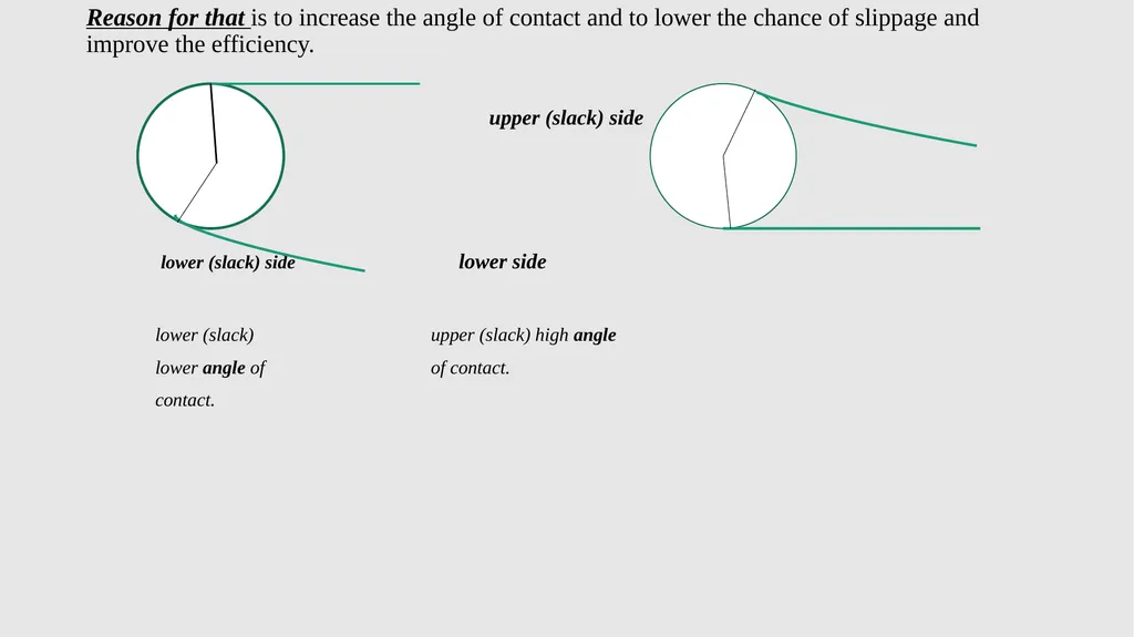
Reason for that is to increase the angle of contact and to lower the chance of slippage and improve the efficiency.
upper side upper (slack) side
lower (slack) side lower side
lower (slack) upper (slack) high angle
lower angle of of contact.
contact.<br>
upper side upper (slack) side
lower (slack) side lower side
lower (slack) upper (slack) high angle
lower angle of of contact.
contact.<br>
90
Material use
Leather belts b) Cotton belts c) Rubber belts
d) Batata belts e) Plastic belts
The material should possess certain qualities, it must be flexible, reliable, and durable.<br>
Leather belts b) Cotton belts c) Rubber belts
d) Batata belts e) Plastic belts
The material should possess certain qualities, it must be flexible, reliable, and durable.<br>
91
Advantages of the Flat belt drive
The flat belts are very simple in design and cheap.
Smooth running and quit running. (they are simple to use).
Flat belts can be used for long distances, even up to 15 m.
Precise alignments of shafts and pulleys are not as critical with flat belts.
Flat belts are very flexible, and therefore they have the ability to bend and twist on pulleys and follow very tortuous path.
Flexible and longer belts can absorb shock and torsional vibration.
Fast and loose clutch action and variable output speed by cone pulley drive are possible with flat belt drive.
They are durable.<br>
92
Disadvantages of the Flat belt drive
High chance of slip off.
Flat belts require significantly greater of pretension to transmit a certain torque without slipping.
They are not advisable for high outputs at high speeds.
Flat belt drive requires a wide pulley so that they can get enough wrap to increase friction and to transmit power without slipping.<br>
93
Chain drives (Pg. 54)
A chain drive is a mechanically operating system where different types of chains are used to transmit the power.
Chain drives come with an endless series of chain links with a net of toothed sprockets.
A chain drive is a positive drive that does not rely on friction to transmit power.
Chain drive is used where the distance between the power produced and where it to be transferred is less.
In chain drive, the speed ratio remains constant which is a major advantages of chain drive.
A chain is made by a number of links and those are connected by the help of pins.
Chains are run over a wheel named sprocket, which has several amounts of teeth around the circumference of that to grip the chain.<br>
94
Chain drive can be classified into Three categories:
Hoisting chains – hoisting is a mechanical device which is used to lift a load or lower a load.
Conveyor chains – they are mostly used in the conveyor. It is a mechanical device system that is used to move the materials from one place to another.
Power transmission chain – it is used to transmit the power. It has greater accuracy and can be easily run over the sprocket.
Roller chains require external lubrication but some use a sintered bush which is impregnated with oil and is therefore self-lubricating.
Drives can be horizontal, vertical or angled.<br>
95
Advantages of chain drives
Lower maintenance.
Greater efficiency up to 97%.
Slipping is negligible.
Chain drive can operate in wet conditions too.
It can withstand abrasive conditions.
The chain drive is easy to install.
Initial tension is not required in chain drive.
Multiple shafts can be driven from a single chain drive.
Require less space and produces less stress on the shaft.
Transmit high power compare to belt drive.
It can be used in reversing drive.<br>
96
Disadvantages of chain drives
It requires more and frequent lubrication otherwise rust problem comes.
It cannot be used where there is a requirement of slips.
We can't keep chain drive in open. It needs housing or covering.
It is noisy and therefore there is a problem of vibration too.
The installation or initial cost is more.
The velocity fluctuation is more when unduly stretched.
Application of chain drives
For power transmission.
For lifting loads and to carry material.<br>
97
Gear drives (Pg. 55)
Gear drive is a mechanical device consisting of toothed wheels that engage and transmit rotary motion.
The centre distance between the shafts is relatively small, which results in compact construction and offer an efficient drive solution.
It is a positive drive and the velocity ration remains constant meaning that no slip occurs..
To avoid slipping, the projections on one disc mesh with the recesses on other disc in gear drives.
Gear can operate in difficult conditions, at almost any angle between input and output.<br>
98
When two gears are in mesh, the small one is called the pinion and the large one the gear or wheel.
The larger gear rotate more slowly than the small gear.
The Three most commonly used types of gear reducer are: (Pg. 56)
Worm Reducer
Worm reducer is also known as Worm gearbox or Worm speed reducer.
It is one type of reduction gearbox which consists of a worm pinion input, an output worm gear, and features a right angle output orientation.
They offer the greatest speed reduction in the smallest package.
The two elements are also called the worm screw and worm wheel.<br>
99
One advantages of worm gear drive units are that they can transfer motion in 90°.
Worm gear reducers are used for speed reduction and increasing the torque for electric motor drive.
These gearbox have high reduction ratio of 60:1 to 100:1 in a single reduction.
They are sturdy, economical and compact and efficient is about 60% (if 10 kW is the input, only 6 kW will come out).
Sliding friction between the worm and wheel make then unsuitable for efficient power transmission.
Applications
Screw conveyers,
Belt and chain conveyors,
Agitator and mixer.<br>
100
Bevel Reducer (Pg. 56)
Bevel gearboxes are ideal when a drive line needs to turn a corner or one drive line needs to power multiple devices from one motor.
They are used to change direction rather than to reduce speed.
Gear ratios range from 1:1 to 4:7.
The axles intersect in gearbox in an angle of 90°.
They are compact and insensitive to shock.
Application
Automotive industry,
Transfer gearboxes,
Machine and plant construction,
Linear technology.<br>
101
Helical Reducers (Pg. 56)
Helical gear can move in both direction.
It is known to work smoothly and quietly.
Helical gear reducers are ideal for heavy load applications, as many teeth come into contact at the sometime to distribute the load and maintain stability.
Applications
Automotive field,
Transport system,
Packaging,
Lift/Pull (Crane, Winch hoist),
Agitator and Mixer.<br>
102
Gearbox Configurations (Pg. 56)
Gear reducing units or gearboxes are used between the input and output to step-up or step-down the speed.
A variety of speed reducers are:
Concentric Shaft Reducer (Pg. 57)
A concentric gear drive is one in which the high and low speed shafts are on the same horizontal and vertical planes.
These units allow several units to be places in a row because of the straight line alignment of their shaft.
They are also called in-line reducers.
The casings are made from cast iron, cast steel or fabricated.
The gears are normally helical gears but some can have spur gears.<br>
103
Parallel Shaft Reducers (Pg. 57)
A parallel gear drive is one in which the high and low speed shafts are on the same horizontal plane and parallel to each other.
Parallel shaft gear-boxes are usually selected for high torque, and high hose power application.
Most parallel shaft reducers use helical gears but some use spur gears.
Reduction can be as high as 300:1.
Single, double or triple reductions are available.
They are used for conveyor belts.<br>
104
Vertical Shaft Output Reducers (Pg. 57)
The vertical drive is a right angle gear drive with the low speed shaft orientated in the vertical direction.
It is typically used in mixing or crushing applications, with the gear drive mounted above or below the equipment.
They are similar to the right-angled reducer, but the output is vertically upwards or downwards.<br>
105
Right-Angled Shaft Reducers (Pg. 57)
A right angle gear drive is one in which the high speed and low speed shaft have a 90° relationship or a right angle relationship.
These drivers are often used on conveyors, or other applications, that require the driving equipment to be close to the driven equipment.
They are mainly bevel gear type reducer, with spiral bevels being popular.
They are used for direction changes or where there is limited space.<br>
106
Advantages of Gear Drives
Gear drives are significantly smaller in dimensions.
High efficiency.
Longer life and greater dependability.
Lack of slippage, and small shaft load.
It can be used to transmit large power.
It has compact layout.
The efficiency of gear drives is very high, up to 99% I case of spur gear.
They are positive and non-slip drive.
They can transmit motion over small centre distance of shaft.
Gear can transmit motion even between non-parallel intersecting shaft.<br>
107
Disadvantages of Gear Drives
Noisy in operation.
It is costlier (than other drives) to manufacture and the maintenance cost is also high.
They need precision manufacturing.
The inaccuracy in cutting teeth can cause vibrations and noise through operation.
Gear drives also requires precise alignment of the shaft.
They are not ideal for large velocities.
Using multiple gear increase machine‘s overall weight.
They have no flexibility.<br>
108
Couplings (Pg. 58)
A coupling is a device used to connect two shafts together at ends for the purpose of transmitting power and torque. (e.g. motors and pump, compressors, and generator).
The primary purpose of couplings is to join two pieces of rotating equipment while permitting some degree of misalignment or end movement or both.
Power can be transmitted by using a coupling, even between axes of different diameters.
The role of a coupling
Power is transmitted from the driving side (turning side) to the driven side (turned side).
Absorbs mounting errors between the axes of the driving side and the driven side.
Absorbs vibration from the driving side and protects surrounding products.
Does not transfer heat from the motor on the drive side, to the driven side.<br>
109
Advantages of using couplings (Pg. 58)
It is difficult and more expensive to manufacture long shafts than shorter shaft.
It is difficult to transport long shaft lengths than shorter lengths.
It takes time and is also difficult to handle and install shaft with long lengths in a workshop.
It is therefore better to use short shaft lengths, joined by couplings, to obtain long shaft lengths.<br>
110
Three Main Types of Couplings (Pg. 58)
1) Rigid Couplings 2) Flexible Couplings 3) Self-aligning Couplings
Rigid and Flexible Couplings
Rigid couplings provide a solid connection between two shafts, high precision and torque, but without misalignment absorption capabilities.
The two shaft must be perfectly aligned when the coupling is fitted.
It allows no movement between the two shafts and they require lubrication in many times.
They cannot absorb vibration, both shafts should be perfectly aligned to ensure a good performance and avoid damping transmission.<br>
111
Rigid coupling may be used to connect two separate systems, such as a motor and generator.
A rigid coupling may also be added between shafts to reduce shock and wear at the point where the shaft meet.
By precisely aligning the two shaft and holding them firmly in place, rigid couplings help to maximize performance and increase the expected life of the machine.
Example of Rigid Couplings
Flange coupling b) Muff or Sleeve coupling c) Clamp coupling<br>
112
Flexible couplings compensate misalignments, movement or deflection between shafts.
Flexible coupling permit some distortions in the mounting beds.
There is no play in a flexible coupling, and it therefore runs silently, without friction and does not need to be greased.
They are very useful when having quick and short starts.
They provide less torque transfer.
They have high capacity to accommodate axial, radial and angular misalignments, reduce transmission of shock load or vibration.
Axial misalignment is an alignment error in the plane of the axis of the shafts.
Radial misalignment refers to an error in the plane of the shaft radius.
Angular misalignment occurs when the shaft centre lines are at an angle to each other.<br>
113
Example of Flexible couplings
a) Gear coupling b) Disc coupling or Diaphragm coupling
c) Chain coupling d) Grid coupling
1.1 Solid Couplings (Pg. 60)
Solid coupling needs a precise alignment between drive motors and the driven equipment.
# Types of Solid couplings
Muff couplings,
Flange couplings,
Marine coupling.<br>
a) Gear coupling b) Disc coupling or Diaphragm coupling
c) Chain coupling d) Grid coupling
1.1 Solid Couplings (Pg. 60)
Solid coupling needs a precise alignment between drive motors and the driven equipment.
# Types of Solid couplings
Muff couplings,
Flange couplings,
Marine coupling.<br>
114
Muff couplings or Sleeve coupling
Muff couplings are used in system where misalignment is neither present nor desired.
The sleeve slips over the shafts so they meet in the middle of the coupling.
They are the simplest type of rigid coupling, consists of a hollow cylinder whose inner diameter is slightly more than shaft diameter.
It is fitted over the ends of the two shafts by means of a gib head key.
The power is transmitted from one shaft to the other by means of a key and sleeve or muff.
The length of the coupling key is equal to the length of the sleeve.
The coupling key is usually made into two parts which may be inserted from the outer ends of the sleeve, thus overcoming the possible misalignment between the keyways.<br>
115
Flange couplings (Pg. 60)
Flange coupling consists of two flanges keyed to the shafts.
The flanges are connected together by means of bolts arranged on a circle concentric to shaft.
Flange coupling consist of two flange, with each flange fitted to the end of each shaft. The flanges are bolted to each other.
Power is transmitted from driving shaft to flange on driving shaft through key, from flange on driving shaft to the flange on driven shaft through bolts and then to the driven shaft through key again.
The inner faces of the flanges are “mated” by a spigot on the one flange to a hole on the other to ensure accurate alignment.<br>
116
Marine coupling (Pg. 61)
They are similar to flange couplings, however the flange is not fitted to the shaft, but forged as one piece.
The bolt holes are accurately bored and reamed to the correct taper only when the flanges are together.<br>
They are similar to flange couplings, however the flange is not fitted to the shaft, but forged as one piece.
The bolt holes are accurately bored and reamed to the correct taper only when the flanges are together.<br>
117
Flexible couplings (Pg. 62)
Flexible couplings are used where the shafts cannot be accurately aligned.
Flexible couplings are usually used to transmit torque from one shaft to another when the two shafts are slightly misaligned.
They can accommodate varying degrees of misalignment up to 3° and some parallel misalignment.
They can also be used for vibration damping or noise reduction.
Misalignments can be one of several fundamental types, including lateral, axial, angular, or skewed.
The grater the misalignment the less efficient the motor is in generating speed and torque.<br>
118
Misalignment contributes to premature wear including broken shafts, failure bearings and excessive vibration.
This coupling is used to protect the driving and driven shaft members against harmful effects produce due to misalignment of shafts, sudden shock loads, shaft expansion or vibration.
Flexible coupling can also provide a form of protection against overloads, while connecting the driving and driven shaft together.
Types of flexible coupling
Pin and rubber bush couplings (leather washers)
Rubber belt coupling
Resilient couplings (Bibby).<br>
119
2.1 Pin and rubber bush couplings (leather washers) (Pg. 62)
Pin and rubber bush couplings are cushioned drive type couplings that transmit the torque through rubber bushes which have an excellent capacity to absorb chocks.
They permit drive in either direction and there is no need for lubrication.
They are smooth and quite in operation and maintenance costs are low.
The composition of the rubber bushes is unaffected by water, dust and atmospheric conditions.
Pin and rubber bush coupling accept parallel, angular and axial misalignment and can provide considerable torsional flexibility.
When the coupling fits together the washers not only stop any shocks and vibration that may occur, they also act as insulators of electric current flowing from motor to machine.<br>
120
2.2 Rubber belt coupling (Pg. 62)
The rubber belt coupling is a torsional elastic coupling.
Rubber-belt couplings are also known as tyre couplings.
They can accommodate misalignment and are also able to absorb shock, vibrations and torsional oscillations.
With a spacer flange, the coupling can be used to accommodate a standard distance between shaft ends and facilitate maintenance.
Rubber belt couplings can accommodate simultaneous maximum misalignment in all planes, without imposing undue loads on adjacent bearings.<br>
121
2.3 Resilient couplings (Bibby) (Pg. 63)
The resilient coupling may be in the form of laminated spring packs or a cylindrical grid member, connecting the driver and driven hubs.
Resilience coupling comprises mainly of two hubs, grid spring and cover to protect the spring to fly off to centrifugal force and to prevent grease to come out.
Spring element take care of angular, parallel or axial misalignment that occurs between rotating shafts, which are independently supported.
They transmit full torque with dampened vibration and reduce peak load.
The primary purpose of resilient coupling is to damped high-amplitude torsional impulses or torque spike.
They are easy to install and simple to maintain.<br>
122
Self-aligning couplings (Pg. 64)
Self-aligning couplings are used in applications involving shaft displacements, high tolerance or misalignments.
They are torsionally stiff. They transmit toques through a mechanically locked connection created by claws/teeth (sliding joints) or pins in bearing bushes (swivel joints).
Self-aligning couplings transmit torque pecks and fluctuations without any damping.<br>
123
Example of self-aligning coupling
Oldham coupling,
Universal (hook's) coupling,
Claw couplings.<br>
Oldham coupling,
Universal (hook's) coupling,
Claw couplings.<br>
124
Oldham couplings (Pg. 64)
The Oldham coupling is used where the axes of the shafts to be joined are not in the a straight line.
The Oldham coupling is a form of flexible coupling designed for applications that must be free from backlash.
Oldham coupling consists of three discs.
Two of the discs are connected to either side of the drive, while the third is sandwiched in between with a torque and groove design.
During operation the center disc slides on the torques of each hub to transmit torque.
Power transmission takes place between the shafts, because of positive connection between the flanges and the central disc.
Oldham coupling are useful in applications with parallel misalignment.<br>
125
Advantages includes
Their compact size and potential for electrical isolation through the plastic center disc.
The couplings may also act a sort of fuse for a machine.
If the torque limits are exceeded the center disc will break apart first and reduces the risk of damage to expensive machine components.
Apply a low reaction force to protect the bearing support.
The drive shaft and the driven shaft rotate at the same speed.
No reaction and torsional stiffness.
Low moment of inertia and easy installation in blinds.<br>
126
Disadvantages Oldham coupling
Accepts relative small angular misalignment's.
Low torque and torsional stiffness.
The driven and driving axes do not move at exactly the same speed in a revolution.
The alignment of the angle is incorrect.
Universal (hook's) couplings (Pg. 64)
This coupling connects shafts whose axes are at an angle other than 180°.
The angle between the shafts may be varied while the shafts are in motion.<br>
127
Friction Clutches (Pg. 65)
The purpose of frictional clutches is to connect a moving member to another that is moving at a different speed or stationary.
Clutch provides a temporary connection between input and output shaft.
Friction clutches utilize friction discs to transfer the energy from one rotating member to a second rotating member.
The friction between the discs of the two bodies allows the friction clutch to transmit torque.
Once the torque capacity of the surface of the friction disc is exceeded, then the friction clutch will slip.
Friction clutches will also slip during engagement and disengagement.<br>
128
Two types of friction clutches
Single-plate clutches (Pg. 65)
In single-plate clutch, power is transmitted by means of friction between the contact surface usually called clutch plates.
Clutch plates has both side friction lining (frictional surface). These surfaces have high coefficient of friction.
The most important part of single plate clutch is clutch plate which consists of a clutch plate with both side friction lining.
Other parts which helps in proper functioning of clutch are: flywheel, pressure plate, thrust bearing, hub, springs and mechanism for engaging and disengaging of clutch.<br>
129
The clutch plate move axially in the driven shaft and is attached with the hub between the flywheel and pressure plate.
It is must in a single plate to have both side friction lining because it is mounted between the flywheel and pressure plate.
The pressure plate is attached with the flywheel and springs.
The main function of pressure plate is to help clutch plate to move towards the flywheel.
A lever is attached to thrust bearings with some mechanism on driven shaft which transmits input and output motion from clutch pedal.
There is a friction plate which is kept in between the flywheel and pressure plate.<br>
130
Working principle of single-plate clutches
Single-plate clutch consists of only one clutch plate, mounted on splines of clutch shaft.
The flywheel is mounted on engine crankshaft and rotates with it.
The pressure plate is bolted on the flywheel with the help of clutch springs and is free to slide when the clutch pedal is pressed.
Clutch shaft is connected to the transmission, thus the engine power is transmitted to the crankshaft to the clutch shaft.
The flywheel remains rotating as long as the engine is running and the speed of clutch shaft reduces slowly and finally it stops rotating.<br>
131
Advantages of single-plate clutches
Smooth in operation,
No cooling oil is required,
Very less slip occurs in its operation,
Power loss is very less,
Very less heat is generated as only one clutch plate is used,
The operation in this type is very fast.
Disadvantages of single-plate clutches
The capacity of torque transmission is less,
The size of this clutch is big even for less torque transmission,
It is dry clutch so it is required to prevent it from moisture,
Chance of tear and wear is high in single-plate clutch,
It require high maintenance.<br>
132
Multiplate clutches (Pg. 66)
This type of clutch has several driving members interleaved or “stacked” with several driven members.
Multi-plate clutches are used in heavy vehicles, with racing cars and motorcycles for transmitting high torque.
There are smooth and easy to operate due to their assembly of friction surface‘s contact.
It may be used where the space is limited.
Other parts which helps in proper functioning of clutch are: pressure plate, clutch plate, thrust springs, clutch pedal, splined shaft and inner splined sleeves, flywheel, diaphragm spring.<br>
133
Working principle of multiplate clutches
Disengaged position
By operating the clutch pedal, the force is exerted against the force of springs ans contact between the flywheel, clutch plates, and pressure plate is lost, and no motion is transferred from flywheel to clutch shaft.
Engaged position
The clutch plates are assembled and are firmly pressed with the help of pressure plate by coil springs. These coil spring exert axial force, due to which there is contact between the clutch plates, flywheel, and the pressure plate. The frictional surfaces on both sides of plates helps to transfer the motion from flywheel to the clutch shaft.<br>
134
Advantages of multiplate clutches
Decrease the weight of the clutch.
It has a very compact size.
Increase the amount of torque transmits.
Decrease the moment of inertia of the clutch.
Disadvantages of multiplate clutches
They heat up quickly.
Multiplate clutches are heavy.
Multiplate clutches are too expensive.<br>
Decrease the weight of the clutch.
It has a very compact size.
Increase the amount of torque transmits.
Decrease the moment of inertia of the clutch.
Disadvantages of multiplate clutches
They heat up quickly.
Multiplate clutches are heavy.
Multiplate clutches are too expensive.<br>
135
Fluid couplings (fluid flywheels) (Pg. 66)
A fluid coupling is a device which allows a controlled amount of slip between input and output between the drive and driven machine, with no mechanical contact.
The fluid coupling consists of a pump impeller (on the input shaft) and a runner (on the output shaft). Both impellers are housed in the same casing.
The pump impeller pushes the fluid inside the casing towards the runner, which causes the output shaft to rotate.
Fluid couplings have no diffuser vanes between the pump and turbine.
The fluid coupling's input and output torque are the same.
When the turbine speed is equal to zero, the fluid coupling has a very high driving torque.<br>
136
If the turbine speed is equal to the pump speed, the torque equals to zero.
The impeller is connected to the input shaft of the prime mover and the turbine is connected to the output shaft where rotation power is needed to be transmitted.
When the impeller is moved by prime mover, the fluid in the housing experiences centrifugal force and due to curved vanes of the impeller the fluid directed towards the turbine blades.
As the fluid strikes the turbine blades, it starts rotating.
With the increase in the speed of impeller, the velocity of the turbine increase and becomes approximately equal to the impeller speed.
The fluid after passing through the turbine blades again return to the impeller.
The impeller and turbine is enclosed in an oil-tight sealed housing.<br>
137
The advantages of Fluid couplings includes:
Smooth acceleration of the load,
Overload protection,
Energy saving (low motor power consumption),
Stepless speed regulation,
Virtually frictionless clutching
High efficiency due to the low sliding.
Application of Fluid couplings
Automotive industries for the transmission of power from the engine to the wheel as alternative of clutch.
In marine propulsion systems.
And for power transmission.<br>
138
Seals (Pg. 70)
A seal is any gasket, packing, seal ring, or other part designed for sealing.
Sealing keeps the hydraulic oil flowing in passages, to hold pressure and keep foreign materials from getting into the hydraulic passages.
Sealing applications are static or dynamic.
Seals are leakage control devices that are design to prevent the leakage of liquids and gases from escaping into the environment.
Types of Seals:
Static seals.
Dynamic seal.<br>
139
Static seals (Pg. 70)
Static seal is a seal that is made between two stable and immovable components.
A static seal is located in a groove and sees no movement – only sealing within its confined space, acting like a gasket between the mating surfaces.
In a static sealing application, there is no movement between sealing surfaces or between the seal surface and its mating surface.
The function of a static seal is to prevent fluid bypass between mating surfaces in which there is little or no relative motion when exposed to zero, low, or high pressure.<br>
140
Type of Static Seals
Gasket seals
A gasket is a mechanical seal which fills the space between two or more mating surfaces (generally to prevent leakage from or into the joined objects while under compression).
Gasket allow for “less-than perfectˮ mating surfaces on machine parts where they can fill irregularities.
Gaskets are commonly produced by cutting from sheet materials.
Some types of gaskets require a sealant be applied directly to the gasket surface to function properly.<br>
141
Gasket is a non-moving object and once it is placed in a particular position, it can't be moved.
Their application include: anti-vibration, packaging, hygiene, noise and sound reduction, and sealing.
For a gasket to function effectively and seal away any leaks, it must be compressed adequately to generate an entire barrier that will make a seal that is pressure-tight and protect the contents inside the seal.
Gaskets are noted to fill irregularities and they are manufactured from sheet materials such as fibreglass, neoprene felt, cork, silicone, rubber, paper, metal, plastic, polymer etc.<br>
142
Dynamic seals (Pg. 71)
Dynamic seal is a seal required to prevent leakage past parts which are in relative motion. (i.e. They are used when there is motion between surface).
Dynamic seal retains or separates fluids, also keeps out contaminants, and contains pressure.
It creates a barrier between moving and stationary surfaces.
Dynamic seals are either contact or clearance. Most dynamic seals are contact seals.
The relative movement of the dynamic sealing system is rotary or reciprocating, separated by a thin layer of oil film, which also serves as a lubricant.
Rotary motion is the movement of the shaft relative to its housing or stationary component.<br>
143
Reciprocating movement is linear motion of a rod or piston in a cylinder.
Seals that actually touch the moving part to complete the sealing process are called contacting seals.<br>
Seals that actually touch the moving part to complete the sealing process are called contacting seals.<br>
144
Types of Dynamic seals
Stuffing boxes (Pg. 71)
Stuffing boxes seal is used to seal rotating or reciprocating shafts.
It find its application in pumps and valves where some leakage from the seal is allow for good maintenance and long shaft life.
The purpose of a stuffing box is to stop liquid in the cylinder from escaping past the shaft.
It is usually part of the cylinder cover, with the gland made of gun metal to the cover.<br>
145
O-ring seals (Pg. 72)
An O-ring is a positive seal that is used in static and dynamic application.
When being installed, an O-ring is squeezed at the top and bottom in its groove and against the mating part.
It is capable of sealing very high pressure. Pressure forces the seal against the side of its groove, and the result is a positive seal on three sides.
It can be stretched, compresses repeatedly and the return to its original form.
Dynamic applications of an O-ring are limited to reciprocating parts that have relatively short motion.
To remove an O-ring seal, special tool made of soft iron or aluminium or a brass rod is needed.<br>
146
Advantages of O-ring seals
Corrosion resistance,
Massive temperature range capabilities,
Excellent electrical properties and an almost unlimited shelf life,
Simple structure, small size and compact installation position,
No need to adjust periodically,
Good sealing performance, will no leak when static sealing,
Size and groove have been standardized, the price is cheap, the product is easy to obtain, easy to use and purchase.
Disadvantages of O-ring seals
When used for compression dynamic sealing, the starting friction resistance is large,
it is difficult to prevent leakage when moving the seal,
The processing dimensions and precision of duel mating parts are strictly required.<br>
147
Oil seals or radial-lip seals
This seal is mainly used on rotating shafts.
The function of the oil seal is to stop whatever fluid is inside from leaking out the clearance between the shaft and housing.
The seal may also be used to prevent outside materials, such as dirt, from moving in through the clearance.
A sealing lip provides a positive seal against low pressure.
A lip is installed toward the pressure source.
Pressure against a lip balloons it out to aid in sealing.
Very high pressure, can get past this kind of seal because it does not have the backup support that an O-ring has.<br>
148
A greater spring may be used in the oil seal to increase the radial interference between the seal lip and contact point on the shaft.
An oil seal normally consists of three basic components: the sealing element, the metal case and the spring.
The purpose of sealing element is to stop the fluid from leaking between the shaft and housing.
The metal case will give rigidity and strength to the seal while it is being held in the bore or recessed groove.
The spring will help make the sealing element more effective.<br>
149
Some advantages of oil seals include:
Very good fitting stability, avoiding pop-out of the seal,
Provides low radial forces
Superior radial stiffness, especially for very large diameters,
Cost effective for expensive elastomer materials,
Suitable for use in combination with axial seal.<br>
Very good fitting stability, avoiding pop-out of the seal,
Provides low radial forces
Superior radial stiffness, especially for very large diameters,
Cost effective for expensive elastomer materials,
Suitable for use in combination with axial seal.<br>
150
Mechanical seals (Pg. 73)
Mechanical seals are leakage control devices, which are found on rotating equipment such as pumps, agitator and mixers to prevent the leakage of liquids and gases from escaping into the environment.
Sealing takes place in a plane perpendicular to the shaft.
A mechanical seal consists of two principle components – one component is stationary and the other rotates with the shaft.
All mechanical seals leak. Like packing, the mechanical seal “facesˮ must also be lubricated. With proper application and design however, the leakage is so minute that actual droplets of liquid are not detected. Instead, the lubricating liquid will vaporize as it crosses the seal faces and the leakage is a gas vapour.<br>
151
Advantages of mechanical seals
Minimum maintenance, it doesn't need to be maintain in normal working conditions.
Reduced leakage when in good condition,
Long working life,
It can handle wide range of liquids including acids, salts and rough particles.
Disadvantages of mechanical seals
More expensive (higher initial cost),
Require a higher standard of fitting,
Provide no support or “steadying” to the shaft,
Can fail rapidly necessitating the immediate shutting down of the pump.<br>
152
Type of mechanical seals
Carbon-ring seals (Pg. 74)
A carbon seal is used to prevent the gas from leaking through the space between a rotating and a static device and thus reducing the efficiency.<br>
Carbon-ring seals (Pg. 74)
A carbon seal is used to prevent the gas from leaking through the space between a rotating and a static device and thus reducing the efficiency.<br>
153
Non-contacting seals (Pg. 74)
When the seal does not make any actual contact with the rotating element it is called a non-contacting seal.
Type of non-contacting seal
Labyrinth seals
A labyrinth seal consists of a series of barriers which prevent the escape of compressible fluids such as gases and vapours. Each strip or rib does not touch the rotating shaft, although the clearance is very small. Each barrier is used to reduce the pressure energy of the fluid so that as it progresses to each new chamber, it loses pressure. They are used on high-speed machinery (e.g. steam turbines and centrifugal compressors). A staggered labyrinth seal provides a more efficient seal.
Disadvantage of labyrinth seal: it is more difficult to manufacture and to maintain.<br>
154
The refrigeration cycle (Pg. 76)
The purpose of a refrigerator is to transfer heat from a cold chamber which is at a temperature lower than that of its surroundings.
Basic knowledge of Thermodynamic
All matter exist in three states: as a liquid, as a solid and as a vapour. (e.g. water is in the form of liquid; solid when it is in the form of ice; and when it is steam it is a vapour).
Temperature determines in what state matter will exist. Any substances has a molecular movement, the hotter a substance is, the faster the molecules will move in that substance. The colder the substance is, the slower will be the movement of the molecules. A thermometer is used to measure the temperature of a substance.<br>
155
Heat is a form of energy which is transferred from one body to another body at a low temperature by virtue of the temperature difference between the body.
The transfer of heat energy from one body to another is known as heat transmission.
Heat always moves from a hot body to a cold body.
The temperature of a substance is its degree of hotness or coldness.
Heat can be transferred from one body to another by three methods:
Conduction
Convection
Radiation.<br>
156
Conduction
It is the transfer of heat from one part of a substance to another part of the same substance in physical contact with it.
Conduction describes how heat moves through a substance.
Convection
It is the transfer of heat within a fluid by the mixing of one portion of the fluid with another.
Convection in fluids is caused by the expansion of the small particles.
Particles expand when heated with the result that their density is low.
The movement of the fluid may be caused by differences in density.<br>
157
Examples of convection currents are: (Pg. 78)
In well-ventilated houses, fresh air enters through the windows and floor ventilators to replace the hot contaminated air. Warm air moves out through the fanlights, air bricks and windows.
Land and sea breezes are actually convection currents.
Radiation
Radiation involves heat passing through space without the aid of a material medium. The transmission through space takes place at a very high velocity
(298 000 km/s). All bodies lose heat by radiation when the surrounding temperature is lower than the temperature of such a body.
Examples of sources of heat radiation:
The sun, fires, radiators, electric lights, boilers, and hot water pipes.<br>
158
The refrigeration cycle (continued)
Refrigeration is accomplished by continuously circulating, evaporating, and condensing a fixed supply of refrigerant in a closed system.
Evaporation occurs at a low temperature and low pressure while condensation occurs at a high temperature and high pressure.
Thus it is possible to transfer heat from an area of low temperature (refrigerator cabinet) to an area of high temperature.
Refrigerant used in refrigerator:
Ammonia – it is fairly volatile substance that is toxic to humans (it is not used anymore),
Chlorofluorocarbons (CFCs) – it is harmful to the environment (it is not used anymore),
Freon (R-12) – Freon is the common refrigerant fount today. It has a boiling point of -30 °C.
NB!!! A refrigerant should have a low boiling point.<br>
159
Vaporisation (Pg. 79)
Vaporisation of an element or compound is a phase transition from the liquid phase to vapour.
Vaporization is a process in which, the liquid is converted into vapour at its boiling point.
As a result of an increase in temperature, the kinetic energy of the molecules increases.
Due to the increases in kinetic energy, the force of attraction between the molecules is reduces.
As a result, they escape into the surrounding in the form of vapours.
This process involves the consumption of heat energy, i.e. when a liquid changes into a gas, the heat is supplied to the gas (absorbed).
An example of vaporisation is when boiling water becomes steam.<br>
160
Evaporation (Pg. 79)
Evaporation is the process of a substance in a liquid state changing to a gaseous state due to an increase in temperature and/or pressure. e.g. if a liquid is placed in the sun it will slowly become a vapour.
Water is transferred from the earthʼs surface to the atmosphere through evaporation.
Evaporation from the oceans account for 80% of the water delivered as precipitation, and the balance occurring on land, inland waters and plant surfaces.<br>
161
Condensation (Pg. 79)
Condensation is the change of water from its gaseous form into liquid water.
Condensation occurs in the atmosphere when warm air rises, cools and loose its capacity to hold water vapour, thus water vapour in the atmosphere is returned to its original liquid state.
Air contains water vapour of varying quantities, and the lower the air temperature is, the lower the capacity for vapour.
When a gas changes into a liquid, heat is given up by the gas (given off).
When substance is put under pressure, its temperature will increase, given off heat to the surroundings if they are cooler.
If the pressure is removed, the substance will cool, meaning that it absorbs heat.<br>
162
The refrigeration cycle in a refrigerator (refer to Fig. 1.99 on Pg. 81) (Pg. 80)
Beginning the cycle at the evaporator inlet (4), the low-pressure liquid expands, absorbs heat, and evaporates, changing to a low-pressure gas at the evaporator outlet.
The compressor (1) pumps this gas from the evaporator (4) through the accumulator, increase its pressure, and discharges the high-pressure gas to the condenser (2).
The accumulator is designed to protect the compressor. An accumulator should be included on all systems subjected to varying load conditions or frequent compressor cycling.
In the condenser (2), heat is removed from the gas then condenses and become a high-pressure liquid.<br>
163
The refrigeration cycle in a refrigerator (continued)
In some system, this high-pressure liquid drains from the condenser (2) into a liquid storage or receiver tank.
Between the condenser and evaporator an expansion device (3) is located.
Immediately preceding this device is a liquid line strainer/drier, which prevents plugging of the valve or tube by retaining scale, dirt, and moisture.
The flow of refrigerant into the evaporator is controlled by the pressure differential across the expansion device.
The refrigerant tend to expand and evaporate. In order to evaporate, the liquid must absorb heat from the air passing over the evaporator.<br>
164
Eventually, the desired air temperature is reached and the thermostat control will break the electrical circuit to the compressor motor and stop the compressor.
As the temperature of the air through the evaporator rises, the thermostat control remakes the electrical circuit. The compressor starts, and the cycle continues.
The operation of a domestic refrigerator (Pg. 81)
A fluid, known as a refrigerant (usually Freon), moves between four key stages in refrigeration cycle. As it does so, it changes in pressure and temperature, this allows the fluid to absorb heat from one place and discharge it in another place.
For a refrigeration cycle to work properly, it requires certain components.<br>
165
The four key stages of temperature and pressure change occur within these components.
Key Components of refrigerator are:
The compressor,
Heat exchanging pipes (known as a condenser and evaporator),
The expansion valve,
Refrigerant,
Thermostat,
Relay.<br>
Key Components of refrigerator are:
The compressor,
Heat exchanging pipes (known as a condenser and evaporator),
The expansion valve,
Refrigerant,
Thermostat,
Relay.<br>
166
Compressor
A refrigerator compressor is an electronic pump that is mounted at the back of the fridge. It's usually makes a humming sound from time to time.
The compressor contains refrigerant gases that assist in the cooling process and sits next to the condenser.
The compressor works as a pump to control the circulation of the refrigerant, and it add pressure to the refrigerant, heating it up.
The compressor also draws vapour away from the evaporator to maintain a lower pressure and lower temperature before sending it to the condenser.
The function of compressor is to pumps the refrigerant through the system and compresses it.<br>
167
Condenser
The purpose of a condenser is to change the hot gas from the compressor to a liquid preparation for use in the evaporator.
The condenser accomplishes this action by the removal of sufficient heat from hot gas, to ensure its condensation at the pressure available in the condenser.
The refrigerant undergoes a phase change process and hence both pressure and temperature remain constant before and after condensation.
Condenser converts a high-pressure and high-temperature refrigerant vapour to a high-pressure and high-temperature liquid refrigerant.
A condenser is generally coil-shaped to increase the surface area to facilitate heat transfer.<br>
168
Evaporator
It is in the evaporators where the actual cooling effect takes place in the refrigeration.
The evaporators are heat exchanger surfaces that transfer the heat from the substance to be cooled to the refrigerant, thus removing the heat from the substance.
In the evaporator the refrigerant enters at very low pressure and temperature after passing through the expansion valve.
This refrigerant absorbs the heat from the substance that is to be cooled so the refrigerant gets heated while the substance get cooled.
The refrigerant leaves the evaporator in vapour state, and is absorbed by the compressor.<br>
169
Expansion valve
Expansion valves are device used to control the refrigerant flow in a refrigeration system.
They help to facilitate the change of higher pressure of liquid refrigerant in the condensing unit to lower pressure gas refrigerant in the evaporator.
It is also used to maintain the difference of pressure between high and low pressure side of the refrigerant.
The expansion valve has a constriction or orifice due to which the pressure of the refrigerant passing through it drops down suddenly to the level of the evaporator pressure.
Due to this, the temperature of the refrigerant also drops down suddenly and it produce cooling inside the evaporator.<br>
170
Thermostat
A refrigerator thermostat is the controlling component of a refrigerator cooling system.
This automatic device keeps the temperature constant and can be adjusted to a desired level.
When the air inside the refrigerator is at the desired temperature, the thermostat stops the flow of electricity to the compressor. When the thermostat senses too much heat, it allows electricity to flow, activating the compressor.
The thermostat has a capillary tube filled with gas. As the temperature in the fridge increases, the gas expands and pushes on diaphragm, which operates a set of contacts which in turn operates the compressor.<br>
171
Relay
A relay in a refrigerator is mounted on the compressor and serves to momentarily apply electricity to a second winding/coil of the compressor motor to give it extra starting torque to commence turning.
When the motor has reached sufficient speed, the relay disconnects the starting winding.<br>
A relay in a refrigerator is mounted on the compressor and serves to momentarily apply electricity to a second winding/coil of the compressor motor to give it extra starting torque to commence turning.
When the motor has reached sufficient speed, the relay disconnects the starting winding.<br>
172
The process of keeping the refrigerator cool: (Pg. 83)
The compressor compresses the ammonia gas. The compressed gas heats up as it is pressurised. The gas leave the compressor at a high-pressure and high-temperature.
The coils on the back of the refrigerator allows the hot ammonia gas to dissipate (lose) its heat. The ammonia gas condenses into ammonia liquid at high-pressure.
The high-pressure ammonia liquid flows through the expansion valve. High-pressure of liquid is reduces and thus cools the liquid.
The liquid ammonia immediately boils and vaporizes, its temperature dropping to -30 °C. this makes the inside of the refrigerator cold.
The cold ammonia gas is sucked up by the compressor and the cycle repeats.<br>
173
UNIT 3 (Pg. 86)
Safety checks on mechanical equipment
Introduction
Accidents can happen anywhere and at any time. To prevent workplace accidents it is essential to take all the necessary precautions and to follow safety procedures with great care.
Mechanical equipment (plant machinery and hand-held power tools) can cause serious injuries. The most common mechanical equipment injuries are to hands and fingers, which may be cut, dislocated, broken, crushed or cut off y machinery or tools.
Workplace must have a maintenance program to ensure that all equipment and machines are in safe working order.<br>
174
Safety procedures when using mechanical equipment (Pg. 86)
No machine may be used or work undertaken unless the technician-in-charge is satisfied that the person is capable of doing so safely.
No person shall mount any abrasive wheel unless he/she has been trained in accordance with the equipment regulations.
Service records of all machine tools, plant and equipment must be kept.
All portable electrical equipment must be regularly inspected and tested for electrical safety.
Lifting equipment must be subjected to annual inspection.
Where applicable, suitable local exhaust ventilation must be used.
During any welding operation, the fume extraction system must be used.<br>
175
Equipment must be cleaned after use. Any materials, tools or equipment used must be tidied away.
Precision measuring equipment, drills, etc. must be replaced in their appropriate cabinets after each working day.
Tools and equipment must not be removed from the workshop without permission from the technician-in-charge.
There are general rules and guidelines for anyone using mechanical equipment to follow.
There are also operational manuals and specific rules for every item of mechanical equipment to be followed by user.
When using a mechanical equipment's, make sure that you adopt a defensive attitude and be aware of the source of danger.<br>
176
Starting and stopping machines (Pg. 86)
Read the owner's manual carefully.
Make sure you understand instructions and are properly trained before operating the machine.
Make sure that the machine has a start/stop button within easy reach of the operator.
Make sure that the machine has an emergency stop button.
Emergency stop – a function that is intended to avert harm or to reduce existing hazards to operator, machinery, or work in progress.
Make sure you identify and deal with the risks from electrical power supplies.<br>
177
Machine guards (Pg. 87)
Guards attached to mechanical equipment protect the user from the moving parts of machines.
Machine guards must never be removed and if a guard is damaged or missing, the machine must not be used until it can be repaired or replaced. A missing or damaged guards must be reported at once.
If guards are removed during cleaning, make sure they are replaced and checked by an authorised person before the machine is used.
Never start machinery during cleaning<br>
178
General safety with machines and equipment (Pg. 87)
Tools are not to be stored on machine beds while the machine is running.
Nothing should be stored on the floor where a tripping hazard may be created.
Any spillages must be cleaned up immediately.
Metal waste bin are provided for chip and scrap.
All possible hazards must be reported.
Portable electrical equipment must be regularly inspected visually.
Portable devices and heavy machinery must be switched off when not in use.
Compressed air must never be used for blowing dust or swarf off clothing, skin or machinery.
Loose clothing, neckties, gloves, rings and other jewellery, long hair should be avoided.<br>
179
Diagnostic analyses of mechanical equipment (Pg. 87)
Amperage
All electric circuits and machines and equipment connected to them can be subjected to overload currents.
To protect machines and prevent damage to equipment, the circuit breakers are place in a circuit.
Purpose of circuit breaker is to stop the supply of electricity to the machine in the event of overload.
Frequent tripping indicate that a fault is present in the circuit or the machine circuit.
A multimeter can be used to find an electrical fault.<br>
180
Vibration (Pg. 88)
Vibration in motorized equipment is the back-and-forth movement, or oscillation of machines and components (e.g. pumps, compressors etc.).
Most industrial machines are design to operate smoothly and avoid vibration, not produce it.
Vibration can indicate problems or deterioration in the equipment.<br>
181
Common cause of vibration in mechanical equipment (Pg. 88)
Imbalance – causes of imbalance are manufacturing errors or maintenance issues.
Misalignment – misalignment may be caused during assembly or developed over time, due to thermal expansion or components shifting.
Wear – as components such as bearings, drive belts or gears become worn, they may cause vibration.
Looseness – looseness can allow any vibration present to cause damage.
Gear wear
Rubbing
Electrical problems in motor – unbalance magnetic force cause vibration
Resonance<br>
182
Noise (Pg. 90)
An unusual sounds in a machine is an indication of a fault.
The machine should be stopped immediately and repaired.
Excessive play
When machine has being in operation for some time, parts begin to wear down which lead to excessive play.
Parts have to be replaced if wear becomes excessive. Physical wear can be measured by means of accurate instruments, e.g. micrometre, vernier calliper etc.
The manufactures of machines and equipment supply data regarding wear of parts.
Manufacture manual must be consulted for exact tolerances and specifications.<br>
183
Oil leaks (Pg. 90)
Crakes in housings/casing, damaged gaskets or broken or worn seal will cause oil to leak.
Overfilling can also be the cause of oil leaks.
In most cases, leaks are easily detected by oil spills on the machine or floor.
Excessive oil consumption may be an indication of an oil leak.
Rust deposits
Corrosion or rust is a sign that there is moisture present. Unless extensive damage has occurred, rust deposits on the external and visible parts of a machine or equipment can be cured simply. All that is required is a thin layer of oil to protect the parts. Remove all signs of rust with a wire brush or sandpaper and then place a protective coating on the part.<br>
184
Rust occurring inside the equipment is dealt with differently.
Lubricants contain rust inhibitors which protect metal surface from oxidation and formation of rust by excluding moisture from penetrating the surface of the lubricant. No rust should be present inside a machine that has lubricant.
Cause of rust formation inside machine
The lubricant may have broken down due to lack of servicing, therefore it is recommended to change oil filters and lubricant.
Water leaking into part of the machine due to a cracked or broken case or damaged seals or gaskets.<br>
185
Reporting faults (Pg. 91)
A report must be compiled after every diagnosis has being carried out on a machine or other equipment.
Normally the report is circulated to consent departments in the company.
Cost, downtime, and general state of machines and maintenance efficiency can be judged.
Keep the report as short and direct as possible, but do not omit any important information.<br>
186
UNIT 4 (Pg. 92)
Safe work practices when working in the vicinity of mechanical equipment
Introduction
To ensure that the machines or equipment's are easily accessible for maintenance, proper operation as well as for loading and removing materials from it, certain amount of free space is needed around it.
Each machine should be made as safe as possible by installing guards and warning signs close to it.<br>
187
Demarcating the location of machines and walkways
Enough space between machines and equipment should be provided so that safety is not compromised.
Space around each machine and equipment depends on the size and function of it.
e.g. A milling machine needs enough space for metal chips that fly off when in operation. Hence adequate space and protecting screens are used.
A walkway between each line of machines is also important so that people can walk safely and materials and components can be moved easily and safely.
Walkways are used as emergency paths to evacuate a building and should be left clear at all times.
Workshop or factory must be arranged in such a way that higher productivity, safe working conditions, better supervision and control is archieved.<br>
188
The use of pallets for component handling (Pg. 93)
Purpose of pallets are used to load finished products that come off production machines. They are usually made of wood, but sometimes plastic pallets are utilise.
Pallets should be of sound construction and of adequate strength for the loads and conditions under which they are used.
Loaded pallets are lifted by means of forklifts or special pallet lifts.
Industry safety standards for the height of working tables (Pg. 94)
No rule as to the height of a workbench exists, however it is recommended that the average height be about 760 mm.<br>
189
Warning and information signs (Pg. 95)
Warning and information signs are used to guide activities and to communicate important information in the workplace.
The purpose of warning signs are to warn people against dangerous situations that could lead to accidents or injuries.
They also instruct workers as to what safety gear to have when carrying out certain task.
The information signs contain information that relate to general emergency situations or other general information.
Warning and information signs should be displayed at appropriate place in the workplace and they should meet SABS standard.<br>
190
Safety attire (Pg. 95)
Personal protective equipment (PPE) can be defined as all equipment that is intended to be worn or used by people at work and which protects them from risky situations that threaten their health and safety.
Example of PPE are:
Overalls, aprons, gloves, screens, leggings, safety helmets, ear protection, eye protection, safety footwear, respirators, safety harnesses and shields, belts etc.
PPE must be provided by the employer as when necessary.
Employee must wear the protective clothing and equipment as and when necessary or when instructed to do so.<br>
191
Adequate workspace, illumination and ventilation in the work area (Pg. 96)
Enough workspace must be made available around each machine or item of equipment as well as around workbenches.
People should be able to work in between and around machines and equipment with easy and without any risk.
Suitable lighting, either natural or artificial, must be provided in every part of the workplace where workers are employed or pass.
Lighting in all work areas should be such that dark shadows and glare are prevented in the work area.
Lack of adequate lighting levels are a potential safety hazard.
All work areas must be adequately ventilated.
The circulation of fresh air by natural or artificial means is important.<br>
192
Legal requirements for safety in the workplace (Pg. 96)
By law every employee must:
Obey all the safety rules of the place of employment
Understand and use, as instructed, the safety practices incorporated in a particular activity or task
Not proceed with any task if any safety requirements are not understood and must then seek guidance.<br>
By law every employee must:
Obey all the safety rules of the place of employment
Understand and use, as instructed, the safety practices incorporated in a particular activity or task
Not proceed with any task if any safety requirements are not understood and must then seek guidance.<br>
193
Pre-operational inspections
Pre-operational inspection of equipment prior to every use will reduce the chance of equipment being operated in an unsafe condition.
Unsafe machinery can also cause injury to the operator or other workers and damage to facilities or product.
Machines showing signs of damage or that have any other kinds of problems should not be put into use until the issue is properly fixed.
Look for coolant, and lubrication leaks.
See that the electrical system is operating within appropriate amp, volt, and current requirements.
Warn people aroung the machine that you are going to start it.<br>
194
Spillage on working surfaces (Pg. 97)
Work areas, walkways should be clearly marked and kept clear and clean.
Spill can easily cause falls.
Clean up spills as soon as possible after they occur and avoid any oily residues on the floor.
Minor spills are spills that can be cleaned up by personnel on the spot.
Procedure to be follow if minor spill occur:
Notify persons in the immediate area and prevent access to the spill.
Evacuate persons in the immediate vicinity of the spill if they are in danger.
If flammable or combustible liquids are spilled, immediately turn off all sources of ignition.
Avoid breathing vapours from the spill. Open windows.
If possible seek assistance in cleaning up the spill.<br>
195
Topic Summary
After completing this topic, you should know:
The difference between static and kinetic friction.
The effect weight has on friction.
The difference between Newton's law of Motion.
The difference between plain and rolling element bearing
The operating principles of mechanical equipment.<br>
After completing this topic, you should know:
The difference between static and kinetic friction.
The effect weight has on friction.
The difference between Newton's law of Motion.
The difference between plain and rolling element bearing
The operating principles of mechanical equipment.<br>
196
After completing this topic, you should know how to:
Recognise different types of pumps.
Measure the surface finish of different parts.
Explain the difference and uses of couplings.
Differentiate between static and dynamic seals
Explain the refrigeration cycle.
Perform safety checks on machines and equipment.<br>
Recognise different types of pumps.
Measure the surface finish of different parts.
Explain the difference and uses of couplings.
Differentiate between static and dynamic seals
Explain the refrigeration cycle.
Perform safety checks on machines and equipment.<br>
197
ASSESSMENT ACTIVITY (Pg. 97 - 98)
SO 1-4 Mechanical fundamentals of the engineering industry
NOTE !!!
Answer Question 1 to 18
You will be Ask to hand in Assessment activity (The date will be given to you).
GOOD LUCK !!!<br>
SO 1-4 Mechanical fundamentals of the engineering industry
NOTE !!!
Answer Question 1 to 18
You will be Ask to hand in Assessment activity (The date will be given to you).
GOOD LUCK !!!<br>
198
TOPIC 2 (Pg. 99) Engineering practices used to construct prototypes
Topic outcomes:
Upon successful completion of this topic, you will be able to:
Interpret, draw and make calculations of a minimally engineered, supported structure capable of bearing a point and/or distributed load.
Design and construct a prototype of a structure for a given design problem.
Test and evaluate the prototype and make any necessary modifications.
Determine the reactions of simply supported, overhanging and cantilever beams.
Calculate and draw the shearing force and bending moment diagrams of beams subjected to concentrated loads, uniform distributed loads and combinations of the two.<br>
199
Introduction
A beam is a structural element that primarily resists loads applied laterally to the beam's axis. In general, a beam is slender, straight, rigid, build from isotropic materials, and most important, subjected to loads perpendicular to their longitudinal axis.
In case of perpendicular loads the member would be subjected to a torque, and it would be called and treated as a shaft. Its mode of deflection is primarily by bending.
The loads applied to the beam result in reaction forces at the beam's support points.
The total effect of all the forces acting on the beam is to produce shear force and bending moments within the beam.
Beams are characterised by their manner of support, profile (shape of cross-section), equilibrium conditions, length, and their material.
Beams primarily carry Vertical Gravitational forces.
Application include: automotive automobile frame, aircraft components, machine frames.<br>
200
Types of Beams
Simply Supported Beam
- Simply supported beam is supported
at the ends by one Roller and a Pin. OR,
- A beam supported on the ends which
are free to rotate and have no
moment resistance.
Cantilever
- A cantilever is a beam rigidly fixed at
one end. OR,
- A projecting beam fixed only at one
end. W W<br>
201
Overhanging beam
W1 W2
- One or both ends of the beam extend
beyond the support. OR,
- A simple beam extending beyond its
support on one or both ends.
Build in beam
W
- Both ends are rigidly fixed at the ends. OR,
- A beam supported on both ends and
restrained from rotation.<br>
W1 W2
- One or both ends of the beam extend
beyond the support. OR,
- A simple beam extending beyond its
support on one or both ends.
Build in beam
W
- Both ends are rigidly fixed at the ends. OR,
- A beam supported on both ends and
restrained from rotation.<br>
202
UNIT 1 (Pg. 102)
Drawings and calculations for a minimally engineered, supported structure
The difference between point loading and distributed loading (Pg. 103)
A Uniformly Distributed Load (UDL)
UDL - A uniformly distributed load is one
whose weight is evenly distributed over the entire surface of the beam.
Distributed load is that acts over considerable loads. The magnitude of the load remains uniform throughout the whole beam.
A load applied across a length instead of at one point.<br>
203
A Point Load
W
L
A point load is one with its weight significantly concentrated in one (or more) places on the beams.
Point load is that load which act over a small distance.
Point load is a force applied at a single point over a small distance.<br>
W
L
A point load is one with its weight significantly concentrated in one (or more) places on the beams.
Point load is that load which act over a small distance.
Point load is a force applied at a single point over a small distance.<br>
204
A load may be classified into the following:
Point load
Point load confined sharply over a single point.
Uniformly or equally distributed load
A load is equally aligned across the whole beam.
Uniformly varying load
Loads distributed over a beam which produces a uniformly increasing load gradient across the entire beam end to end is called a uniformly varying load.<br>
205
Shear Force Diagrams (SFD) (Pg. 112)
The purpose of shear force diagram
The purpose of SFD is to determine the point of maximum bending moment, where the maximum stress will be and failure will first occurs.
The purpose of SFD is to determine the Area of high shear force to see where extra reinforcing must be place.
Maximum bending moment will be at the turning point on the SFD, this is where the shear force is zero. SFD will be drawn from the left to right.
At the ends of a simply supported beam the shear force is zero.
At the wall of a cantilever beam the shear force equals the vertical reaction at the wall. At the beam's free end the shear force is zero.<br>
206
On any beam segment where no loads are applied, the shear force remains constant (horizontal line).
A point or reaction on a shear force diagram generates an abrupt change in the graph, in the direction of the applied load.
A uniform distributed load acting on a beam is represented by a straight line shear force with a negative or positive slope, equal to the load per unit length.
A shear force diagram is one which shows variation in shear force along the length of the beam.
NB !!! The diagram above zero line (horizontal line) represents the positive SF and the diagram below the zero line the negative SF.<br>
207
Sign Convention (Pg. 112)
The signs of the shear and moment are important. The sign is determined after a section cut is taken and the reactions are solved for the portion of the beam to one side of the cut.
The shear force at the section cut is considered positive if it causes clockwise rotation of the selected beam section, and it is considered negative if it causes counter-clockwise rotation.
The bending moment at the section cut is considered positive if it compresses the top of the beam and elongates the bottom of the beam (i.e. if it makes the beam ''smile'').
Base on this sign convention, the shear force at the section cut in the figure below is positive since it causes clockwise rotation of the selected section. The moment is negative since it compresses the bottom of the beam and elongates the top (i.e. it make the beam ''frown'').<br>
208
M V M V
V M V M
What is a shear force?
A shear force occurs when a perpendicular force is applied to a beam.
Shearing forces are internal forces developed in the material of a beam to balance externally applied forces in order to secure equilibrium of all parts of the beam. + -<br>
V M V M
What is a shear force?
A shear force occurs when a perpendicular force is applied to a beam.
Shearing forces are internal forces developed in the material of a beam to balance externally applied forces in order to secure equilibrium of all parts of the beam. + -<br>
209
To calculate the shear force of a beam, follow the following steps:
Start with the far left side of the beam
If there is upward force, then the SFD will start at this force above the x-axis.
If there is a downward point load and no support, then the SFD will start as negative at the value of the point load.
Move across the beam
As you come across loads, you simply add or subtract these load from the value you already have, keeping a cumulative TOTAL.
Things to keep in mind:
The area under the SFD above the x-axis should be equal to the area below the x-axis, i.e. the area should sum to zero.
Any points where the SFD cross the x-axis, will be a max or min bending moment. The SFD should always equal to zero at both ends.<br>
210
Bending moment diagrams (BMD) (Pg. 118)
A bending moment is the reaction induced in a structural element when an external force or moment is applied to the element causing the element to bend.
A bending moment (BM) is a measure of the bending effect that can occur when an external force (or moment) is applied to a beam.
The concept of bending moment is important in structural engineering as it can be used to calculate where, and how much bending may occur when forces are applied.
The Bending Moment Diagram (BMD) shows where and how the moments will act on the beam, i.e. how a beam will bend, on application of a load or a combination of various types of load.<br>
211
The most common structural element that is subjected to bending moments is the Beam, which may bend when loaded at any point along its length.
A beam may fail due to shear force before failure in bending.
If a beam is not well-restrained, a bending force may cause it to rotate about a pivot point. Bending moment is the force trying to rotate the member.
To calculate the bending moment, the magnitude of the force is multiplied by the distance of the force from the point of support.
At the end of a simply supported beam, the bending moments are zero.
At the wall of a cantilever beam, the bending moment equals the moment reaction. At the free end, the bending moment is zero.
At the location where the shear force crosses the zero axis the corresponding bending moment has a maximum value.
Basically bending moment diagram is the integral of shear force diagram.<br>
212
What is a bending moment?
A moment is a rotational force that occurs when a force is applied perpendicularly to a point at given distance away from that point.
It is calculated as the perpendicular force multiplied by the distance from the point.
A bending moment is simply the bend that occurs in a beam due to a moment.
It is important to remember two things when calculating bending moment,
The standard units are Nm and
Clockwise bending is taken as negative.<br>
213
General rules for drawing SFD and BMD<br>
214
45 kN 54 kN 18 kN
a c d e b (FBD)
0,6 m 0,6 m 0,6 m 0,6 m
L R
42
18
0 0 (SFD)
-3
-57
25,2 23,4
0 0 (BMD)
-10,8<br>
a c d e b (FBD)
0,6 m 0,6 m 0,6 m 0,6 m
L R
42
18
0 0 (SFD)
-3
-57
25,2 23,4
0 0 (BMD)
-10,8<br>
215
Unit 2 (Pg. 122)
Design and construction of a prototype of a structure
Introduction
The neutral axis is an axis in the cross section of a beam (a member resisting bending) or shaft along which there are no longitudinal stresses or strains, i.e. the material of the beam is not under stress, either compression or tension).<br>
216
Calculations and their representation in the prototype design (Pg. 122)
When a simply supported beam is unloaded as show in figure below, the length a-b and c-d will be the same as well as the neutral axis.
When a simply supported beam is loaded as show in figure below, whether the loads are point, uniformly distributed or both, the beam will bend as shown.
At the neutral axis the length of the beam will not be affected but length a-b will become smaller and length c-d longer. The top face will be in compression and the bottom face in tension.
Neutral axis Load
a b a Compression b
c d c Tension d<br>
217
Neutral Axis (Pg. 124)
The neutral axis is the axis through a beam where the stress is zero, that there is neither compression nor tension.
The location of the neutral axis depends on the relative stiffness and size of each of the material sections.
It is a line through the centre of area of the cross-section at right angles to the applied load.
Neutral axis is perpendicular to the plane of the loads.
When a piece of metal is bent, one surface is stretched while the other surface is compressed. There is then an area between the two surfaces that experiences zero stress, called Neutral Axis. The maximum stress occurs at the surface of the beam farthest from the neutral axis.<br>
218
compression tension d<br>
219
D d<br>
220
15 kN/m<br>
221
5 kN/m<br>
222
TOPIC 3 (Pg. 142) Functionally Dependent Mechanisms in Prototypes
Topic outcomes:
When you have completed this topic, you will be able to:
Describe functionally dependent mechanisms.
Design and construct a prototype to solve a given design problem.
Test and evaluate the prototype and make any necessary modifications.<br>
Topic outcomes:
When you have completed this topic, you will be able to:
Describe functionally dependent mechanisms.
Design and construct a prototype to solve a given design problem.
Test and evaluate the prototype and make any necessary modifications.<br>
223
UNIT 1 (Pg. 145)
Functionally dependent mechanisms
Introduction
When one system relies on another system to work, we say that it is functionally depended on the second system.
Functionally dependent mechanisms are multiple systems in which each unit system depend on a previous system to work.
When an object moves it can have one of four types of motion or a combination of these types of motion.<br>
224
The dependence of components that are linked to produce motion
A body is said to be in motion if it changes its position with respect to its surroundings.
Motion is a continuous change in position of an object.
Four types of motion
Linear motion: it is a motion in a straight line (e.g. objects falling vertically down, a train/locomotive).
Rotary motion: it is anything that moves in a circle (e.g. a gear rotating about an axis, a bicycle wheel).
Reciprocating motion: it is a repetitive movement left to right or up and down (e.g. a piston in an engine, when you saw wood).
Oscillating motion: something that oscillates moves back and forth (e.g. classic pendulum clock, rotary actuator).<br>
225
Mechanisms and components that change motion from one form to another (Pg. 146)
There are many types of mechanisms that can change linear motion to rotary motion and vice versa.
Example of mechanisms that change motion from one form to another
Cams
A Cam is the typical mechanical component used in rotary-linear motion conversion mechanism. Cams are mechanical devices that convert rotational motion into linear motion (e.g. valves of internal combustion engines).
A cam is a rotating or sliding piece in a mechanical linkage used in transforming rotary motion into linear motion.
A cam mechanism consists of two moving elements, the cam and the follower.<br>
226
As the cam rotates, the follower rises and falls in a process known as reciprocating motion.
The follower maintains contact with the cam through the force of gravity or by a spring. The follower is in a sleeve, so that it can move in one direction only.
The total range of movement produced by the cam is called the stroke.
Cams are commonly used in engines to control valves (in which the valve is the follower), and sewing machines.
As the cams rotate, the followers reciprocate motion according to the profile of each cam. (cam profile – snail shape, pear shape, and circular shape)
Cam can provide a lift (up movement), fall (down movement), and dwell (no movement).
The shape of the cam is altered to give the movement that is required in the mechanism.<br>
227
Wheel and axle
A wheel and axle is another example where rotary motion can be changed to linear motion.
The wheel and axle consists of a round disc, known as a wheel , with a rod through the centre of it, known as the axle.
The axle is larger than the wheel.
The wheel and axle system changes the force by changing the distance over which the force must be applied.
The wheel and axle both rotate at the same rate.
A wheel and axle system need a force in order to lift the load, but that force can be less than the weight of the object.<br>
228
Linkages
Simple linkages change the direction of motion and the amount of force.
Examples of linkages
Levers can be joined together to form linkages.
Reverse motion linkages change the direction of input so that the output goes the opposite way.
A fixed pivot forces the change in direction.
Changing the placing of the fixed pivots changes the amount of force exerted, while keeping the direction the same (e.g. toolbox with drawers opens up effectively using parallel motion linkages).<br>
229
Bell crank linkages change the direction of force through 90°. The amount of output force can be change by moving the fixed pivot.
When used in bicycle brakes, the rider can pull the brakes from the handlebars, which changes direction through the bell crank to make the brake pads touch the wheel.
Crank and slider linkages change rotary motion into reciprocating motion. A fixed pivot is attached to a crank, which turns around and pushes and pull a slider.
Treadle linkages use a rotary input to turn a crank on a fixed pivot. A connecting rod joins two moving pivot. (e.g. pair of windscreen wipers on a car, moving backwards and forwards together).<br>
230
Crankshafts
A crankshaft is a rotating shaft which (in conjunction with the connecting rods) converts reciprocating motion of the pistons into rotational motion.
Crankshafts are used in internal combustion engine and consist of a series of cranks and crank pins to which the connecting rods are attached.
The crankshaft rotates within the engine block through use of main bearings, and the crankpins rotate within the connecting rods using rod bearings.
The explosion of the fuel drives the piston downwards.
A crank will cause the rod to move back and forth, and the movement of rod will cause the crank to turn.
The crankshaft is a tough alloy steel forging and provides a constant turning force to the wheels.<br>
231
Flywheels
The flywheel is a disc that is bolted to the crankshaft at the rear of the engine.
There is a toothed ring on its outer edge that the starter turns to start the engine.
Once they are spinning they gain more momentum and help the engine run smoother and shift smoother at higher RPM.
Flywheel is a mechanical device specifically designed to efficiently store rotational energy (kinetic energy). Store energy and release the energy when needed.
Flywheels resist changes in rotational speed by their moment of inertia.
The heavy weight of the flywheel suppresses the engine vibration and wobbles, helping to stabilize and balance the engine on its mounts and reduce vibration throughout the vehicle.<br>
232
Functions of the flywheel are: (Pg. 149)
Flywheel stores the significant amount of energy and release it when required.
Flywheel reduce the fluctuation of torque, make crankshaft rotation uniform.
Flywheel enables to continue the mechanism through the dead center.
It provides a balance for the crankshaft of the engine.
Flywheels facilitate overcoming the short time overload, e.g. the starting of an engine from the rest.
It serves as a mounting surface for the clutch and pressure plate assembly.
It control speed variation in an engine.<br>
233
Starting engine
The gear teeth cut into the flywheel's circumference support starting the engine.
In the engine's starter motor, a small gear (Bendix gear) mates up to the flywheel when you turn the key.
The Bendix gear/starter motor combination spins the flywheel, turning the crankshaft and beginning the compression cycle required to start the engine.
After the engine starts, the Bendix gear withdraws to let the flywheel spin freely.
Once the engine has started, the crankshaft converts the up-and-down movement of the pistons into rotary motion.
The mass of the flywheel applies inertia to keep the engine crankshaft turning between each of these piston firings, so the rotation speed of the crankshaft is kept constant and the engine runs smoothly.<br>
234
Differentials
A differential is a system that transmits an engine's torque to the wheels.
The differential takes the power from the engine and splits it, allowing the wheel to spin at different speeds.
The differential distributes equal amounts of torque to both wheel. This permits the wheel to react to traction, to give the wheel more resistance to rotate less. The wheel with less resistance rotate faster.
When a vehicle is going in a straight line, all wheels are traveling at the same rotational speed. During a turn, the outside wheel travel at a higher rotational speed than the inside wheel.<br>
235
Components of differentials
Rear axle housing – holds all other components and attached to the vehicle's suspension.
Ring and pinion gears – provide a final gear reduction, transfer power 90° to the wheel.
Differential assembly – contains the differential case which attaches to the ring gear.
- includes the side gears and differential pinion gears that allows to turn at different speeds.
Axles – transmit power from the differential to the wheels.
Type of Axle housing – Integral carrier type and Removable carrier type.<br>
236
Differential Operation
The drive pinion drives the ring gear which is attached to the differential case.
When going straight – the differential housing and its components rotate as an assembly. Power is transferred equally to both wheels.
When turning a corner – the wheels must travel at different speeds to prevent tire scrubbing. Differential pinion gears turns around slower side gear and cause other side gear to turn faster. The percentage of speed that is removed from one wheel is given to the other wheel.
Purpose of axle assembly
To transmit power from the drive shaft to the wheels.
To turn the power flow 90° on rear wheel drive cars.
To allow the wheels to turn at different speeds while cornering.<br>
237
Wheels
Wheels reduce friction. Instead of simply sliding over the ground, the wheels dig in and rotate, turning around sturdy rods called axles. Wheels provide leverage.
Wheels work more effectively when they have a smooth road surface to travel on.
The purposes of wheel in automotive vehicle are:
To observe the impact forces of the road surface and to bear the vehicle load.
Transfers the rotational movement of the axles to tyres.
Absorbs and transfers the braking and accelerating forces.
Dissipates the braking heat to the atmosphere and
Act as a seal in case of tubeless tyres<br>
238
Function of a wheel rim are:
The function of wheel rims are to boost the performance and look of the wheel.
The rim must be strong enough to support the weight of the car.
The rim must be able to resist the torque on it caused by pulling off and braking the vehicle.
The rim must be able to withstand the stresses of side thrust due to cornering.
The wheel rim must permit the mounting and removal of the tyre and retain it securely in position when inflated.<br>
239
Tyres
An inner liner, made of air-tight rubber, which is used on most modern car tyres in place of the old inner tube. This does the important job of keeping the tyre rigid, and improves the ride for all passengers by absorbing road bumps through being able to expand and compress according to the terrain.
Functions of a tyre are:
To maintain contact between vehicle and ground by providing desired traction.
Dealing with various forces acting on vehicle during its motion.
Tyres support the vehicle chassis off the ground.
Tyres helps absorbs shocks from the road surface.
Tyres help to transmit acceleration, breaking and cornering forces to the road surface.
Tyres help to change and maintain the direction of travel.<br>
240
Body and frame
The function of the body in a vehicle is to support the vehicle's mechanical components and body.
Also to deal with static and dynamic loads, without undue deflection or distortion.
The major systems of an automobile are the engine, fuel system, exhaust system, cooling system, lubrication system, electrical system, transmission, and the chassis.
The chassis includes the wheels and tires, the brakes, the suspension system, and the body.
The frame, also known as the chassis, is the main supporting structure of a motor vehicle, to which all other components are attached.<br>
241
Electrical system
The main function of the electrical system is to generate, store and supply the electric current to various systems of a vehicle.
A vehicle's electrical system consists of the battery, starter and alternator, distributor, ignition coil, and ignition switch.
The battery provides juice to the starter. Then, the alternator gives that battery the energy it needs to power the vehicle.
The energy from the battery is supplied to the starter (consumer), which then starts the vehicle engine. During vehicle operation, the ignition and fuel injection system, the control units, the electronic, the lighting, and other equipment have to be supplied with power.<br>
242
Turning the key in the ignition switch draws current from the battery. This current, however, is not strong enough to provide spark to the spark plugs so it is drawn through the ignition coil.
The introduction of current between the primary and secondary windings creates a powerful magnetic field.
The magnetic field collapse many times a second due to current flow interruption.
The collapsing of the magnetic field produces a powerful electrical surge. Hence 12-volt current from the battery is converted to the 20,000 volts needed as spark to ignite the fuel.
The powerful current must be distributed by the distributor to each spark plug in a carefully controlled sequence.
This sequence must be timed so that the cylinders and the pistons powering the crankshaft work smoothly together.<br>
243
Hydraulic motion (Pg. 153)
The principle behind any hydraulic system is simple: forces that are applied at one point are transmitted to another point by means of an incompressible fluid.
The most important use of hydraulics in vehicle is in hydraulic braking systems.
These system use brake fluid to transfer pressure onto a braking pad, which then presses onto the axel and stop the vehicle from moving.
In braking systems, the piston driving the fluid is smaller than the pistons operating the brake pads therefore the force is multiplied helping you to brake easily and more efficiently.
Pipes containing the fluid can be any size, length or shape allowing the lines to be fed almost anywhere.<br>
244
They can also be split to enable one master cylinder to operate two or more slave cylinders if needed.
Main parts of hydraulic brake:
Master cylinder (lever) –
The master cylinder, mounted to the handlebar, houses the brake lever and together they produce the input force needed to push hydraulic brake fluid to the slave cylinder and cause the brake pads to clamp the rotor.
The master cylinder can be divided into Three categories:
Dead-stroke
Pad gap stroke
Contact and modulation<br>
245
Lines -
Hydraulic brake lines or hose play the important role of connecting the two main working parts of the brake, i.e. the master cylinder and slave cylinder.
Hydraulic hoses are multi-layered in their construction and consist of three layer:
(Inner tube, Aramid layer, Outer casing)
Brake Fluid
Brake fluid is a type of hydraulic fluid used in hydraulic brake applications in vehicles.
It is used to transfer force into pressure, and to amplify braking force.
When you apply your foot to the brake pedal, brake fluid transfers this force into pressure to the front and rear brakes and stops the vehicle.
It works because liquids are incompressible.
Brake fluid is subjected to very high temperatures, especially in the wheel cylinders of drum brakes and disc brake slave cylinder.<br>
246
Slave cylinder -
The brake slave reside at each wheel and respond to the master cylinder input generated by the user.
The master cylinder input is converted to clamping force as the pistons move the brake pads to contact the rotor.
Pads – (Organic brake pads, Semi-metallic brake pads and Ceramic brake pads)
Organic brake pads contain no metal content. They are made of rubber, Kevlar and even glass. Advantage of organic pads is that they‘re made of materials that don’t pollute as they wear.
They are also softer than other brake pads and as a result quitter. Disadvantages are that organic pads wear down faster and they perform poorly in wet conditions.<br>
247
Semi-metallic pads contains metal content which change things slightly. It can improve the lifespan of the pad quite significantly as metal wears slower than organic materials.
Disadvantages of semi-metallic pads are that noise is increase in usage and the harder compound means increased wear on the rotor.
Ceramic brake pads are an alternative/upgrade mountain bike brake pad.
Advantages of a ceramic material then is one which can cope with extreme heat and keep performing strongly. They also produce a lot less dust than other brake pad compound.<br>
248
Rotor –
Rotor size has a direct effect on braking power.
The larger the brake rotor the more power will be produced for any given input.
Pistons –
The pistons are the cylindrical components housed within the slave cylinder.
Upon master cylinder input they protrude to push the brake pads which contact the rotor.<br>
249
Designing a simple trolley jack hydraulic circuit (Pg. 155)
A jack is a mechanical lifting device used to apply great forces or lift heavy load.
The most common types are car jack (bottle jack), and trolley jack (floor jack) which lifts vehicles so that maintenance can be performed.
Trolley jack and bottle jack can provide a greater lift with lesser application of force.
A hydraulic jack is a jack that uses a liquid to push against a piston. This is based on Pascal's Principle that states that pressure in a closed container is the same at all points.
If there are two cylinders connected (a large and a small one), applying force to the smaller cylinder will result in the same amount of pressure in the larger cylinder.
However, since the large cylinder has more area, the resulting force will be greater.
An increase in area lead to an increase in force.<br>
250
Trolley jack
Unlike bottle jack shafts which operate vertically, the shaft in a floor jack is horizontal.
The shaft pushes on a crank that connects to a lifting pad, which is then lifted vertically.
Floor jacks typically provide a greater range of vertical lift than bottle jacks.
A trolley jack uses force multiplication to lift heavy loads.
Lifting the handle of the trolley jack draws oil into the pump cylinder. Lowering the handle of the trolley jack pushes pressurised oil to the main cylinder. This causes the main piston to raise after pumping the trolley jack several times.<br>
251
Design of a hydraulic circuit – A basic hydraulic circuit consists of power supply, pump, reservoir, relief valve and control valve, actuator or cylinder.
Step One
The job to be done by actuator is assessed, this enables us to determine the type and size of actuator needed. A trolley jack is required to lift motor vehicles for access beneath the vehicle. Also knowing the job to be done indicates to us that the actuator should be a cylinder.
Step Two
We need to know how to get the oil pressure to the cylinder. Trolley jacks employ manual pumping rather than a motorised pump, therefor the pump will be a reciprocating piston type. Fig.3.14 on Pg.156.<br>
252
Step Three
During the pumping stroke, the actuator will lift a load upwards. During suction stroke (to allow more fluid into the cylinder), the load on the actuator will push down on the actuator piston, forcing the fluid back to the pump and tank and lowering the load.
To overcome this, a valve called a check or non-return valve is utilised. Non-return valve allows flow in one direction only. Fig. 3.15 on Pg. 156.
Step Four
After each stroke of pumping, the actuator will have lifted the load a little higher until the actuator reaches its maximum position. To ensure that too high a pressure is not reached, which may rupture the seals and cause serious damage, a pressure release valve designed for an appropriate working pressure is installed. Fig. 3.16 on Pg. 157.<br>
253
Step Five
To lower the load, a directional valve that can be set manually for lifting and lowering is required.
This directional valve has two positions: one during pumping stroke and one for the lowering action.
The valve is a two-way valve, which allows fluid to flow in one of two ways at a time. Fig. 3.17 on Pg. 157.<br>
254
Pneumatic motion (Pg. 158)
A pneumatic system consist of a piston in cylinder, a directional control valve, pressure regulator, compressor, air tank, pneumatic hoses, FRL.
In a pneumatic system, energy that will be used by the system and transmitted through the system is stored as potential energy in an air receiver tank in the form of compressed air. A pressure regulator is positioned after a receiver tank and is used to portion out this stored energy to each part of the circuit.
A directional valve directs the flow of air in one with another. It doesn’t throttle or meter the air flow, and it doesn’t change the pressure of the air. It just changes the direction of the airflow in some way.
For the valve to shift from one position to another, the actuator is installed.
The purpose of actuator is to cause the valve to move from one position to another.<br>
255
Working principle of pneumatic motion
Figure 3.19 shows a three-port valve that controls the flow of air in a pneumatic system.
Port 1 is connected to the air reservoir and port 2 to the single-acting cylinder while port 3 is the exhaust port.
When the button is activated, the air flow to the cylinder through port 1 and 2, overcoming the force of the piston spring and thus moving the piston of the cylinder forward.
When the button is deactivated, ports 2 and 3 are lined up, opening the air passage to exhaust.
The spring in the cylinder forces the piston backwards, allowing the air to escape.<br>
256
Pneumatic symbols (Pg. 159)
Fig. 3.20 on Pg. 159 shows the symbols of the three-port valve and the single-acting cylinder.
Fig. 3.21 on Pg. 159 shows two ways that the valve can be activated: by hand using a push button, and by using a wheel for the valve operation.
Any of various tools and instruments that generate and utilize compressed air are classified as Pneumatic device. e.g. Rock drillings, Pavement Breakers, Riveters, Forging presses, Paint sprayer, Blast cleaners, etc.
Compressed air power is flexible, economic and safe.
Disadvantage of Pneumatic system
a) Relatively low accuracy b) low loading c) Processing required before use d) noise
e) Uneven moving speed.<br>
257
Advantages of Pneumatic system
Low initial cost and design simplicity.
High effectiveness.
High durability and reliability.
High adaptability to harsh environment.
Easy selection of speed and pressure.
Environmental friendly.
Safety.
Pneumatic systems are light in weigh.
Operating elements are cheaper and easy to operate.<br>
Low initial cost and design simplicity.
High effectiveness.
High durability and reliability.
High adaptability to harsh environment.
Easy selection of speed and pressure.
Environmental friendly.
Safety.
Pneumatic systems are light in weigh.
Operating elements are cheaper and easy to operate.<br>
258
Electric motor (Pg. 160)
An electric motor is an electrical machine that converts electrical energy into mechanical energy.
Generally we use an electrical motor to make a device rotate or move. e.g. pumps, motor driving compressor, industrial fans, blowers, machine tools, and household appliances etc.
Electric motor can be powered by Alternating current (AC) sources, such as a power grid, inverters or electrical generators or Direct current (DC) sources, such as from batteries, motor vehicles or rectifiers.
Most electric motors operate through the interaction between the motor's magnetic field and electric current in a wire winding to generate force in the form of torque applied on the motor's shaft.
The reverse task of converting mechanical motion into electricity is done by a generator.<br>
259
Electric motors may be classified by considerations such as power source type, internal construction, application and type of motion output.
In addition to AC versus DC types, motors may be brushed or brushless, may be of various phase (single-phase, two phase, or three-phase), and may be either air-cooled or liquid-cooled.
Electric motors produce linear or rotary force (torque) intended to propel some external mechanism, such as a fan or elevator.
An electric motor is generally designed for continuous rotation, or for linear movement.<br>
260
Magnetism and magnetic fields (Pg. 160)
Magnetism is one aspect of the combined electromagnetic force. The motion of electrically charged particles gives rise to magnetism.
A magnetic field is a vector field that describes the magnetic influence of electric charges in relative motion and magnetised materials.
Magnetism is the force exerted by magnets when they attract or repel each other.
Magnetism is caused by the motion of electric charges. To magnetised, another strongly magnetic substance must enter the magnetic field of an existing magnet.
The magnetic field is the area around a magnet that has magnetic force. All magnets have north and south poles.
Opposite poles are attracted to each other, while the same poles repel each other.<br>
261
Some substances can be magnetised by an electric current. When electricity runs through a coil of wire, it produces a magnetic field. The field around the coil will disappear as soon as the electric current is turned off.
Magnetic fields can be shown using field lines. Magnetism is induced in some materials when placed in a magnetic field.
Magnets create magnetic fields. These magnetic fields cannot be seen. They fill the space around a magnet where the magnetic forces work, and where they can attract or repel magnetic materials.
Although we cannot see magnetic fields, we can detect them using iron filings.
The tiny pieces of iron line up in a magnetic field.<br>
262
Drawing magnetic field diagrams
In the diagram, note that:
The field lines have arrows on them,
The field lines come out of North pole and South pole,
The field lines are more concentrated at the poles.
The magnetic field is strongest at the poles, where the field lines are most concentrated.<br>
In the diagram, note that:
The field lines have arrows on them,
The field lines come out of North pole and South pole,
The field lines are more concentrated at the poles.
The magnetic field is strongest at the poles, where the field lines are most concentrated.<br>
263
Uniform magnetic field
When magnetic field lines are the same distance apart from each other, we say that the magnetic field is uniform. This is shown in the diagram:
N S
Magnetic field lines in a uniform field<br>
When magnetic field lines are the same distance apart from each other, we say that the magnetic field is uniform. This is shown in the diagram:
N S
Magnetic field lines in a uniform field<br>
264
Current Flow (Pg. 162)
When an electric current flows in a conductor, it flows as a drift of free electrons in the metal. Conductors are the material which have free electrons.
Electricity flows easily through a conductor because the electrons are free to move around in the object. Whenever there is a movement of electrons through a conductor, an electronic current is created.
An electric current flowing through a conductor produces magnetic field in its surrounding region.
The nature of the magnetic field lines around a straight current carrying conductor is concentric circles with centre at the axis of the conductor.
The direction of the magnetic field lines of force around a conductor is given by the Maxwell's right hand grip rule or the right handed corkscrew rule.<br>
265
If the direction of current in conductor is upward then the magnetic field line is anticlockwise as shown in the diagram (a). And if the direction of current is downward in the conductor then the magnetic field line is clockwise as shown in the diagram (b).
current (upward)
Diagram (a)
Conductor Magnetic field lines (anticlockwise)
Magnetic field line (clockwise)
Diagram (b)
Current (downward)<br>
current (upward)
Diagram (a)
Conductor Magnetic field lines (anticlockwise)
Magnetic field line (clockwise)
Diagram (b)
Current (downward)<br>
266
Ideal electric machines (Pg. 163)
Electric machine consist of the following components: (Fig.3.29 on Pg. 164)
Stationary outer member called the Stator – the stator is the stationary part of the motor's electromagnetic circuit and usually consists of either windings or permanent magnets. The stator core is made up many thin metal sheets called laminations. Laminations are used to reduce energy losses that would result if a solid core were used.
Inner rotating member called the Rotor – the rotor turns the shaft to deliver the mechanical power. The rotor usually has conductors laid into it that carry currents, which interact with the magnetic field of the stator to generate the forces that turn the shaft. Alternatively, some rotors carry permanent magnets, and stator holds the conductors.<br>
267
Bearings – the rotor is supported by bearings, which allow the rotor to turn on its axis. The bearings are in turn supported by the motor housing. The motor shaft extends through the bearings to the outside of the motor, where the load is applied. Because the forces of the load are exerted beyond the outermost bearing, the load is said to be overhung.
Air gap – the distance between the rotor and stator is called the air gap. The air gap has important effects, and is as small as possible, as a large gap has a strong negative effect on performance. The magnetising current increases with the air gap. Very small gaps may pose mechanical problems in addition to noise and losses.<br>
Air gap – the distance between the rotor and stator is called the air gap. The air gap has important effects, and is as small as possible, as a large gap has a strong negative effect on performance. The magnetising current increases with the air gap. Very small gaps may pose mechanical problems in addition to noise and losses.<br>
268
Windings – windings are wires that are laid in coils, usually wrapped around a laminated soft iron magnetic core so as to form magnetic poles when energised with current.
Commutator – a commutator is a mechanism used to switch the input of most DC machines and certain AC machines. It consists of slip-ring segments insulated from each other and from the shaft. The motor's armature current is supplied through stationary brushes in contact with the revolving commutator.
Brushes – brushes are connected to the terminals of the power source, allowing electric power to flow into the commutator.
Armatures – the armature is the electromagnet, also called a coil, and is made up of many separate windings which create an electric field. It acts directly with the field magnet which is a permanent magnet. As long as the armature has electrical current flowing through it, creating a magnetic field, the armature will rotate and thus spin the rotor shaft.<br>
269
How electric motor work (Pg. 164)
An electric motor is all about magnets and magnetism, a motor uses magnets to create motion. Electric motor work on a simple principle base on electromagnetism.
Opposites attract and likes repel. If two bar magnets with their ends marked North and South, then the north end of one magnet will attract the south end of the other. On the other hand, the north end of one magnet will repel the north end of the other (south will repel south).
Inside an electric motor, these attracting and repelling forces create rotational motion.
To make the rotation continuous, the commutator changes the direction of current flow every half rotation. With the change of the direction of current flow, the wire can rotate continuously in the same direction.<br>
270
Operation of a simple motor (Pg. 166)
An electric motor is an electrical machine which converts electrical energy into mechanical energy.
The basic working principle of a DC motor is: whenever a current carrying conductor is placed in a magnetic field, it experiences a mechanical force.
When armature windings are connected to a DC supply, an electric current sets up in the winding.
Magnetic field may be provided by field winding (electromagnetism) or by using permanent magnets.
In this case, current carrying armature conductors experience a force due to the magnetic field.<br>
271
Commutator is made segmented to achieve unidirectional torque.
Otherwise, the direction of force would have reversed every time when the direction of movement of conductor is reversed in the magnetic field.
Electric motors generate magnetic fields with electric current through a coil.
The magnetic field then causes a force with a magnet that causes movement or spinning that runs the motor.<br>
272
Types of direct current (DC) motors (Pg. 167)
Mainly there are two types of DC motors. First one is Separately Exited DC motor and Self-excited DC motor.
The self-excited motors are further classified as Shunt wound or Shunt motor, Series wound or Series motor and Compound wound or Compound motor.
DC motor consist of rotor-mounted windings (armature) and stationary windings (field poles).
In all DC motors, except permanent magnet motors, current must be conducted to the armature windings by passing current through carbon brushes that slide over a set of copper surfaces called commutator, which is mounted on the rotor.
The commutator bars are soldered to armature coils.<br>
273
The brush/commutator combination makes a sliding switch that energises particular portions of the armature, based on the position of the rotor.
This process creates north and south magnetic poles on the rotor that are attracted to or repelled by north and south pole on the stator , which are formed by passing direct current through the field windings.
It is this magnetic attraction and repulsion that causes the rotor to rotate.<br>
This process creates north and south magnetic poles on the rotor that are attracted to or repelled by north and south pole on the stator , which are formed by passing direct current through the field windings.
It is this magnetic attraction and repulsion that causes the rotor to rotate.<br>
274
Series-wound motors (Pg. 167)
Series-wound motor falls under the category of self-excited DC motors.
The field winding in this case is connected internally in series to the armature winding.
The field is wound with a few turns of large wire because it must carry the full armature current.
A characteristic of series motors is the motor develops a large amount of starting torque. Speed varies widely between no load and full load.
Series motors lack good speed regulation.
Series motors cannot be used where a constant speed is required under varying load.
The speed of a series motor with no load increases to the point where the motor can become damaged. Some load must always be connected to a series-connected motor.<br>
275
Shunt motor (Pg. 167)
Shunt motors use high-resistance field windings connected in parallel with the armature.
Shunt motors are prone to armature reaction.
The shunt-connected motor offers good speed regulation.
The field winding can be separately excited or connected to the same source as the armature.
An advantage to a separately excited shunt field is the ability of a variable speed drive to provide independent control of the armature and field.
The shunt-connected motor offers simplified control for reversing.<br>
276
Compound wound motor (Pg.168)
A DC motor having both shunt and series field windings is called a compound motor.
Compound motors have a field connected in series with the armature and a separately excited shunt field.
The series field provides better starting torque and the shunt field provides better speed regulation.
The motor connects in two different arrangements: cumulatively and differentially.
Cumulative compound motors attach the series field to the shunt field, which causes higher starting torque but less speed regulation.
Differential compound motors have high-speed regulation and usually operate at a constant speed.<br>
277
Brushless DC motors
Brushless DC motor have one or more permanent magnets in the rotor and electromagnets on the motor housing for the stator.
A motor controller changes DC to AC. This design gets rid of the complication of transferring power from outside the motor to the spinning rotor.
The motor controller senses the rotor's position through sensors and can precisely control the timing and phase of the current in the rotor coil to optimise torque, conserve power, regulate speed, and apply some braking.
Brushless motors have a long life span, require little or no maintenance, and have high efficiency.
They do have some disadvantages, including their high initial cost and more complicated motor speed controllers.<br>
278
Types of alternating current (AC) motors (Pg. 168)
The two main types of AC motors are Induction motors and Synchronous motors.
All AC motors are made up of a magnetic circuit formed by a stationary member called a Stator and a rotating member known as Rotor. The stator and rotor are separated by an Air Gap.
The stator has primary windings that are connected to the power source and develop a rotating magnetic field.
The rotor has secondary windings that rotate in the magnetic field created by the stator windings. This causes currents to flow in the secondary windings and causes development of a secondary magnetic field.<br>
279
This group of induction machines includes electrical machines whose mode of operation is based on a rotating magnetic field in the air gap between the stator and rotor.
The most important and most used machine in this group is the synchronous AC induction motor with a squirrel cage design. It is characterised by the following features:
A simple and robust design
High operational reliability
Low-maintenance operation
A low cost.<br>
The most important and most used machine in this group is the synchronous AC induction motor with a squirrel cage design. It is characterised by the following features:
A simple and robust design
High operational reliability
Low-maintenance operation
A low cost.<br>
280
Induction motor (Pg. 168)
The machine which converts the AC electric power into mechanical power by using an Electromagnetic Induction Phenomenon is called an Induction motor.
The induction motor is mainly classified into two types: the Single Phase induction motor and Three Phase induction motor.
In an induction motor, the magnetic field in the windings of the rotor is induced by the magnetic field of the stator. In order for this induction to produce torque, the speed of the rotor's field must lag the field of the stator's magnetic field.
This speed differential is known as “Slipˮ, and is the reason that induction motors will have a “nameplate RPMˮ rating that is about 5% less than their synchronous speed.
AC induction motor have no brushes and have a much longer life expectancy.<br>
281
Working Principle of an Induction motor
In an induction machine, the armature winding serve as both the armature winding and field winding.
When the stator windings are connected to an AC, supply flux is produced in the air gap. The flux rotates at a fixed speed called synchronous speed.
This rotating flux induces voltages in the stator and rotor winding.
If the rotor circuit is close, the current flows through the rotor winding and react with the rotating flux and a torque is produced. In the steady state, the rotor rotate at speed very close to synchronous speed.<br>
282
Synchronous motor
The motor that converts the AC electrical power into mechanical power and is operated only at the synchronous speed is known as a synchronous motor.
A synchronous electric motor is an AC motor in which, at steady state, the rotation of the shaft is synchronised with the frequency of the supply current, the rotation period is exactly equal to an integral number of AC cycles.
The synchronous speed is the constant speed at which motor generates the electromotive force. Synchronous motor is used for converting the electrical energy into mechanical energy.
The stator and the rotor are the two main parts of the synchronous motor. The stator becomes stationary, and it carries the armature winding of the motor.
The armature winding is the main winding because of which the EMF induces in the motor. The rotator carry the field windings. The main field flux induces in the rotor.<br>
283
Working Principle of a Synchronous motor
When supply is given to synchronous motor, a revolving field is set up.
This field tries to drag the rotor with it, but could not do so because of rotor inertia. Hence, no starting torque is produced. Thus, inherently synchronous motor is not a self-starting motor.
The stator and rotor both are excited separately.
The excitation is the process of inducing the magnetic field on the parts of the motor with the help of an electric current.
When the three phase supply is given to the stator, the rotating magnetic field developed between the stator and rotor gap.
The rotor enters into the rotating magnetic-field produced by the stator winding and rotates in synchronisation.<br>
284
The speed of the synchronous motor is independent of the load, i.e. the variation of the loads does not affect the speed of the motor.
The three phase stator winding gives the advantage of determining the direction of rotation.
Synchronous motors are used for applications where precise and constant speed is required.
Low power applications of these motors include positioning machines.<br>
The three phase stator winding gives the advantage of determining the direction of rotation.
Synchronous motors are used for applications where precise and constant speed is required.
Low power applications of these motors include positioning machines.<br>
285
Stepper motors (Pg. 170)
Stepper motors are specialised types of motors that utilise electromagnets for precision rotation in both clockwise and anticlockwise directions.
These magnets are arranged in cyclical patterns, and are turned on and off in a particular order to effectively turn the shaft to specific points, with each defined point referred to as a “step”. Each pulse moves the shaft through a fixed angle.
Stepper motors effectively have multiple toothed electromagnets arranged around a central gear-shaped piece of iron.
The electromagnets are energised by an external driver circuit or a micro controller.<br>
286
Working Principle of Stepper motors
To make the motor shaft turn, first, one electromagnet is given power, which magnetically attracts the gear's teeth. When the gear's teeth are aligned to the first electromagnet, they are slightly offset from the next electromagnet.
When the next electromagnet is turned on and the first is turned off, the gear rotates slightly to align with the next one. From there the process is repeated.
Each of those rotations is called a “stepˮ, with an integer number of steps making a full rotation. In that way, the motor can be turned by a precise angle (15°).
The circular arrangement of electromagnets is divided into groups, each group called a phase, and there is an equal number of electromagnets per group.
The electromagnets of each group are interleaved with the electromagnets of other groups to form a uniform pattern of arrangement.<br>
287
UNIT 2 (Pg. 172) Designing and Constructing a Prototype
Introduction
The purpose of design/engineering drawing is to communicate your ideas to other people in the simplest form possible.
Any new design must be placed on a drawing whether it is two dimensional or three dimensional or both.
Initial drawings don’t need to be elaborated or fancy.<br>
Introduction
The purpose of design/engineering drawing is to communicate your ideas to other people in the simplest form possible.
Any new design must be placed on a drawing whether it is two dimensional or three dimensional or both.
Initial drawings don’t need to be elaborated or fancy.<br>
288
The design process (Pg. 172)
The engineering design process is a common series of steps that engineers use in creating functional products and processes.
Among the fundamental elements of the design process are the establishment of objectives and criteria, synthesis, analysis, construction, testing and evaluation.
Schematic drawing is widely used in engineering because it shows the function of each component as well as their relative positions to each other.
There are standard procedures and practices for all drawings, such as the use of the correct symbols and codes for each component.
The schematic is the master drawing from which other drawings can be make for each components.<br>
289
Comparing the prototype to previous design faults (Pg. 173)
The purpose of this stage is to take the preliminary prototype and compare it to previous design faults to asses where any improvements to the design can be made.
Fundamental design problems are easily resolved if previous similar designs are available for comparison.
Comparing the prototype to design specification (Pg.173)
One the prototype has been built it must be compared to all the design specifications to see whether they are met.
Factors that have to be included in the prototype final design are international and national standards.<br>
290
UNIT 3 (Pg. 176)
Introduction
The new design need to be properly evaluated to see if specifications are met.
It should be tested as close as possible to its working environment to avoid any problems during its operation.
The record should be kept for all tests and modifications for future reference.<br>
Introduction
The new design need to be properly evaluated to see if specifications are met.
It should be tested as close as possible to its working environment to avoid any problems during its operation.
The record should be kept for all tests and modifications for future reference.<br>
291
Simulations and field testing
Prototype must be evaluated in the environment in which it is to be used.
A prototype is an early sample, model, or release of a product built to test a concept or process.
Testing prototypes is an inherent part of finalising design.<br>
Prototype must be evaluated in the environment in which it is to be used.
A prototype is an early sample, model, or release of a product built to test a concept or process.
Testing prototypes is an inherent part of finalising design.<br>
292
Checking the prototype against design specifications and analysing results
The specification of a new design is a detailed requirement that must be met by the design solution.
The finished product must be able to perform to the required standard.
The prototype design must be justified according to its design specifications.
The prototype design must meet these specifications with either little or no change in the specifications.
In the case where the specifications can easily be changed, the results can easily be justified.
Design verification is a method of confirmation by examining and providing evidence that the design output meets the design input specifications.<br>
293
Topic summary
After completing this topic, you should be able to:
Design a simple hydraulic circuit.
Design a simple pneumatic circuit.
Explain the basic principles of electric motors.
Employ the design process to design a prototype.<br>
After completing this topic, you should be able to:
Design a simple hydraulic circuit.
Design a simple pneumatic circuit.
Explain the basic principles of electric motors.
Employ the design process to design a prototype.<br>
294
ASSESSMENT ACTIVITY (Pg. 179)
SO 1-3 Functionally dependent mechanisms in prototypes
NOTE !!!
Answer Question 1 to 18
You will be Ask to hand in Assessment activity (The date will be given to you).
GOOD LUCK !!!<br>
SO 1-3 Functionally dependent mechanisms in prototypes
NOTE !!!
Answer Question 1 to 18
You will be Ask to hand in Assessment activity (The date will be given to you).
GOOD LUCK !!!<br>
295
TOPIC 4 (Pg. 180)
Control Systems Topic Outcomes:
Upon successful completion of this topic, you will be able to:
Explain and sketch different control systems.
Construct a control system to solve a given design problem.
Test and evaluate the prototype and make any necessary modifications.
Apply the prototype according to organisational requirements<br>
296
UNIT 1 (Pg. 182)
Different Control Systems
Introduction
A control system manages, commands, direct, or regulate the behaviour of other devices or systems using control loops (closed-loop and open-loop).
For continuously modulated control. A feedback controller is used to automatically control a process or operation.
The control system compares the value or status of the process variable (PV) being controlled with the desired value or setpoint (SP), and applies the difference as a control signal to bring the process variable output of the plant to the same value as the setpoint.<br>
297
Control system provides the desired response by controlling the output. Traffic lights is one example.
Control systems are used to enhance production, efficiency and safety in many areas, including: sugar refining plants. Metal and mines, sewage treatment plants, water treatment plants, nuclear power plants, boiler controls and power plant, etc.
Control system is the execution of at least four different basic functions in turn,
There are:
Sensing or information receiving
Information storage
Information processing
Decision and action.<br>
298
The basic functions of a central system (Pg. 182)
Information sensing or receiving
Control systems are composed by five main elements: Sensors, Transducers, Transmitters, Controllers, and final control elements or actuators.
Sensor is defined as a device that converts a physical stimulus into a readable output.
The role of a sensor in a control system is to detect and measure some physical effect, providing this information to the control system.
Many sensors act as a switch, controlling the flow of electric charges through the circuit. Most sensors use radiation such as light or laser, infraredradio waves or other waves such as ultrasonic waves to detects objects and changes in their environment.<br>
299
Information storage, processing and decision making (Pg. 183)
The information storage in machines are: Random Access Memory (RAM) chips, Optical disk, USB flash drives, Hard disks.
In a machine, microchips are programmed to make a decision.
Action (Pg. 183)
Action follows a decision making and can be corrective in a control system.
The essentials of a basic automatic control system are:
A controlled condition,
A measuring unit,
A regulating unit,
A controlling unit.<br>
300
Different control systems (Pg. 184)
Common control systems include:
Mechanical control systems
Hydraulic control systems
Pneumatic control systems
Electronic control system
Computer aided control system.
A system usually contains three main parts: Input, Process And Output.
The force applied to the load is the output of the Mechanical System.<br>
301
Mechanical control systems
Example of mechanical control systems
Governor – A mechanical governor consist of weighted balls, or flyweights, that experience a centrifugal force when rotated by the action of the engine crankshaft. The interaction of the governor spring and mechanical governor holds the throttle at the desired engine RPM based upon a force balance and the load/operating conditions. The centrifugal force generated by the flying hammer during the rotation can automatically adjust the fuel inlet amount when the engine set speed changes, thereby achieving the purpose of automatically adjusting the unit speed. If small engine under a light load is in operation, the carburettor needs to deliver a relatively small amount of air-fuel mixture to the combustion chamber. As the crankshaft spins, centrifugal force causes the flyweights to open. As they open, they apply pressure to the governor cup and governor crank, which are linked to the throttle. The throttle is pulled toward the closed position.<br>
302
Advantages of mechanical governors
They are cheap.
They can be used when it is not necessary to maintain an exact speed depending on the load.
They are simple in construction and have only a few parts
Cruise control – Principle of function in mechanical cruise control is based on a position control of throttle. Cruise control is an electromechanical system consisting of: a speed sensor, sensor of brake and clutch pedals, controller and actuators. All these elements work together with a control unit that processes input signals and controls the output variables. The data about vehicle velocity are the basic for function of the cruise control.<br>
303
Cruise control (speed control or autocruise) is a system that automatically controls the speed of a motor vehicle. The system is servomechanism that takes over the throttle of the car to maintain a steady speed as set by the driver.
The driver must bring the vehicle up to speed manually and use a button to set the cruise control to the current speed.
The cruise control takes its speed signal from a rotating driveshaft, speedometer cable, wheel speed sensor from the engine's RPM, or from internal speed pulses produced electronically by the vehicle.
All cruise control system must be capable of being turned off both explicitly and automatically when the driver depresses the brake, and often also the clutch.<br>
304
Hydraulic control systems (Pg. 186)
A hydraulic system controls the transmission of energy. It transforms the mechanical energy of a prime motor into fluid energy.
Hydraulic systems feature high power density, sensitive response and precision of control, especially when operating under computer control.
Hydraulic control systems use the pump to push hydraulic fluid through the system to create fluid power.
The fluid passes thought the valves and flow to the cylinder where the hydraulic energy converts back into mechanical energy.
The valves help to direct the flow of the liquid and relieve pressure when needed.<br>
305
Pneumatic control system (Pg. 187)
A pneumatic control system uses compresses air as a method of control.
Compressed air is carried via copper and plastic tubes from a controller to a control device, usually a damper or valve actuator.
This control method relies on sensors and thermostats that bleed or retain the line pressure from the sensor to the control device and the actuator.
Each sensor responds to changes in temperature, humidity, and static pressure to provide feedback in a control loop to open or close the actuator to meet the control set point.
The actuators contain diaphragms and spring to function in sequence with the control signal. This system uses the compressed air as the communication method.
The compressed air is usually filtered and dried to protect the cylinders, actuators, and tools performing the work.<br>
306
Each thermostat in a building with a pneumatic control system has one or more air lines connected to it from the main source of compressed air and to some type of final device such as a valve.
The actuator required no maintenance except for inspection and adjustment of the mechanical linkages.
Pneumatic system are used in controlling train doors, automatic production lines, mechanical clamps, etc.<br>
The actuator required no maintenance except for inspection and adjustment of the mechanical linkages.
Pneumatic system are used in controlling train doors, automatic production lines, mechanical clamps, etc.<br>
307
Components of a control system (Pg. 187)
Control system consist of FIVE basic components:
Sensor - the role of a sensor in control system is to detect and measure some physical effect, providing this information to the control system. A sensor can be defined as a device that receives a stimulus and responds to it with a signal. The sensor can output whether an object is present or not present (binary) or what measurement value has been reached (analog or digital).
The most common sensors are:
For Motion States - position, velocity, acceleration, and mechanical strain,
Temperature States - temperature and heat flow
Fluid States - pressure, flow, and level,
Electromagnetic States - voltage, current, charge, light, and magnetic flux.<br>
308
A sensor is a device that detects and responds to some type of input from the physical environment. The specific input could be light, heat, motion, moisture, pressure, electrical signals, smoke, gas, alcohol, etc.
A sensor is a device, module, machine, or subsystem whose purpose is to detect events or changes in its environment and send the information to other electronics, frequently a computer processor.
A sensor's sensitivity indicates how much the sensor's output changes when the input quantity being measured changes, e.g. if the mercury in a thermometer moves 1 cm when the temperature changes by 1 °C, the sensitivity is 1 cm/°C.
Advantages of sensor are: their accuracy, low cost, and high performance etc.
Disadvantages are: they can be affected by environmental changes and contamination, e.g. a gas that they are measuring can affect the performance of the sensor.<br>
309
Classification of sensors based on their sensing principle, with example<br>
310
Controller – a controller is a mechanism that seeks to minimise the difference between the actual value of a system and the desired value of the system.
Once the sensor has detected a disturbance and taken a measurement, the information needs to be processed and an action taken, if required.
The processing can be carried out by means of a mechanism, electronics circuit or computer.
A control system manages, commands, directs, or regulates the behaviour of other devices or systems using control loops. It can range from a single home heating controller using a thermostat controlling a domestic boiler to large industrial control systems which are used for controlling processes or machines.
They are two main types of controllers:
a) Continuous controllers b) Discontinuous controllers<br>
311
Controllers generally receive voltage inputs from sources, analyse the inputs, and then oversee condition changes via signal outputs.
Controllers are classified according to the energy source that powers them. They can be electrical, hydraulic, mechanical or pneumatic.
The controller read the measured Process Variable, meaning what you got.
The controller knows what you want, meaning setpoint.
The controller compares what you got (PV) to what you want (SP).
The controller makes a decision based on the comparison, meaning hold steady, increase, decrease.
The controller holds or changes its output.<br>
312
The uses of the controllers include:
Controllers improve the steady-state accuracy by decreasing the steady state error.
As the steady-state accuracy improves, the stability also improves.
Controllers also help in reducing the unwanted offsets produced by the system.
Controllers can help in reducing the noise signals produced by the system.
Controllers can control the maximum overshoot of the system.
Controllers can help to speed up the slow response of an overdamped system.
Control systems are used to enhance production, efficiency and safety in many areas, including: chemical plants, pulp and paper mills, boiler controls and power plant, nuclear power plants, water treatment plants, sewage treatment plants, etc.<br>
313
Actuators (Pg. 188)
An actuator is a component of a machine that is responsible for moving and controlling a mechanism or system, eg. Opening/closing a valve.
An actuator requires a control signal and a source of energy.
The control signal is relatively low energy and may be electric voltage or current, pneumatic or hydraulic pressure, or even human power.
An actuator is a device that puts the processed information into action or physical motion.
An actuator can move something in a straight line, referred to as linear, or in a circular motion, referred to as rotary.
It also can be used to apply a force.<br>
314
When it receives a control signal, an actuator responds by converting electric energy into mechanical motion (rotary or linear motion).
The sensor measure a disturbance to the system and then send a signal to the controller.
The controller receives the signal and determines whether a change is needed in the system.
The actuator is then instructed by the controller to move the valve's position.
In the industrial mechatronics system, they are solely responsible for ensuring a device such as a robotic arm is able to move when electric input is provided. Cars uses actuators in the engine control system to regulate air flaps for torque and optimisation of power, idle speed, and fuel management for idle combustion.<br>
315
Stepper motor (Pg. 188)
Stepper motors are DC motors that move in discrete steps. They have multiple coils that are organised in groups called “phasesˮ. By energising each phase in sequence, the motor will rotate, one step at a time.
Stepper motors are used for accurate rotation angle and speed control using pulse signals.
Stepper motors generate high torque with a compact body, and are ideal for quick acceleration and response. Stepper motors also hold their position at stop, due to their mechanical design.
Stepper motors consists of driver (takes pulse signals in and converts them to motor motion) and a stepper motor.
Stepper motor drivers convert pulse signals from the controller into motor motion to achieve precise positioning.<br>
316
The motor operates by accurately synchronising with the pulse signal output from the controller to the driver.
To control the speed of a stepper motor, you control the time between steps. And as long as there is enough excess torque to keep up, you can control the position, speed, and acceleration.
The step movement may be angular or linear.
Modern stepper motors can reach rotation speeds of up to 1500 RPM, taking into consideration that the motor torque curve decreases considerably with the increasing of the step frequency.
Stepper motor, with their ability to produce high torque at a low speed while minimising vibration , are ideal for applications requiring quick positioning over a short distance.
A stepper motor rotates with a fixed step angle. The angle is called “basic step angle”.
A pulse signal is an electrical signal whose voltage level changes repeatedly between ON and OFF. Each ON/OFF cycle is counted as one pulse. A command with one pulse causes the motor output shaft to turn by one step.<br>
317
The amount the stepper motor rotates is proportional to the number of pulse signals given to the driver.
The speed of the stepper motor is proportional to the speed of pulse signals given to the driver.
Stepper motor continue to generate holding torque even at standstill. This means that the motor can be held at a stopped position without using a mechanical brakes.
Working principle of stepper motor:
The stepper motor rotor is a permanent magnet, when the current flows through the stator winding, the stator winding produce a magnetic field. The magnetic field drives the rotor to rotate by an angle.
When the stator's magnetic field is rotated by an angle, the rotor also rotates with magnetic field at an angle.
Each time an electrical pulse is input, the motor rotates one degree further.
Change the order of winding power, the motor will reverse.<br>
318
Servo motors (Pg. 188)
The function of the servo motor is to receive a control signal that represents a desire output position of the servo shaft and apply power to its DC motor until its shaft turns to that position.
Servo implies an error sensing feedback control which is utilised to correct the performance of a system.
It uses the position-sensing device to figure out the rotational position of the shaft, so it knows which way the motor must turn to move the shaft to the instructed position.
The servo motors usually have a revolution cut off from 90° to 180°. Servo motors do not rotate constantly. Their rotation is limited between the fixed angles.
The shaft commonly does not rotate freely around similar to a DC motor, however rather can just turn 200°.<br>
319
The servo motor is an assembly of FOUR things: a normal DC motor, a gear reduction unit, a position-sensing device, and a control circuit.
The DC motor is connected with a gear mechanism that provides feedback to a position sensor which is mostly a potentiometer.
From the gearbox, the output of the motor is delivered via servo spline to the servo arm. The gear is normally made up of plastic whereas, for high power servos, the gear is made up of metal.
A servo motor is controlled by controlling its position using Pulse Width Modulation Technique. The pulse width determines the angular position of the servo motor. e.g a pulse width of 1ms causes an angular position of 0°, whereas a pulse width of 2 ms causes an angular width of 180 °.<br>
320
Working principle of servo motor:
From the position of the rotor, a rotating magnetic field is created to efficiently generate torque. Current flows in the winding to create a rotating magnetic field.
The shaft transmits the motor output power. The load is driven through the transfer mechanism.
High-function rare earth or other permanent magnet is positioned externally to the shaft.
To Optical Encoder always watches the number of rotations and the position of the shaft.
The DC motors get powered from a battery and run at high speed and low torque.
The position sensor senses the position of the shaft from its definite position and feeds the information to the control circuit.
The control circuit accordingly decodes the signals from the position sensor and compares the actual position of the motors with the desired position.<br>
321
Advantages of servo motor:
If heavy load is placed on the motor, the driver will increase the current to the motor coil as it attempts to rotate the motor.
There is no out-of-step condition.
High-speed operation is possible.
Disadvantages of servo motor:
Since the servomotor tries to rotate according to the command pulses but lags, it is not suitable for precision control of rotation.
Higher cost.
When stopped, the motor's rotor continues to move back and forth one pulse, so that it is not suitable if you need to prevent vibration.
Application of servo motor includes:
Machine tools, packaging, factory automation, material handling, printing converting, assembly lines, CNC machinery,
They are also used in radio-controlled airplanes to control the positioning and movement of elevators,
They are used in many radio controlled toys and in electronics devices such as DVD.<br>
322
Open-loop and Closed-loop control systems (Pg. 190)
The two main kinds of control systems are the open-loop and closed-loops system.
They are used either individually or in combination with:
Feed-forward control
Sequential control
Fuzzy logic.<br>
The two main kinds of control systems are the open-loop and closed-loops system.
They are used either individually or in combination with:
Feed-forward control
Sequential control
Fuzzy logic.<br>
323
Open-loop control systems
In an open-loop controller, also called an non-feedback controller, the control action from the controller is independent of the process output.
It does not use feedback to determine if its output has achieved the desired goal of the input command or process set point.
There are many open-loop controls, such as on/off switching of valves, machinery, lights, motor or heaters, where the control result is known to be approximately sufficient under normal conditions without the need for feedback.
The advantage of using open-loop control is the reduction in component count and complexity. An open-loop system cannot correct any errors that it makes or correct for outside disturbances, and cannot engage in machine learning.<br>
324
An open-loop control system is a control system in which the system output does not influence the control actions.
In an open-loop control system, a sequence of control actions is precomputed and stored in a feedforward controller, then executed when a trigger is activated.
Once the control action is initiated, it cannot be adjusted based on the system response.
Feedforward controllers are usually used when there is no feedback available or the interaction with the environment is reasonably predictable.
An open-loop control system is simply a condition on a functioning machine whereby the system has two basic states: “ON” or “OFFˮ.
The machine will stay ON/OFF for as long as the operator leaves it in that mode.<br>
325
Advantages of Open-loop Control System
Simple in construction and design.
Economical.
Easy to maintain.
Generally stable.
Convenient to use as output is difficult to measure
Disadvantages of Open-loop Control System
They are inaccurate.
They are unreliable.
Any change in output cannot be corrected automatically.<br>
Simple in construction and design.
Economical.
Easy to maintain.
Generally stable.
Convenient to use as output is difficult to measure
Disadvantages of Open-loop Control System
They are inaccurate.
They are unreliable.
Any change in output cannot be corrected automatically.<br>
326
The term “open-loopˮrefes to the lack of sensor feedback to control the operation of the machine.
An example of an open-loop feedback would be a simple light switch that, upon activation, remains in the On or Off condition until manually changed.
Input Output
Open Loop System
Example: consider the clothes dryer whose control action is done manually by the operator. Depending on the wetness of the clothes, suppose the operator set the timer for 30 min. after 30 min the timer will stop even after the clothes are still wet. Controller Controlled Process<br>
327
Closed-loop or feedback control (Pg. 191)
Electrical Energy
Desire Heat Actual output
input
Error
Feedback loop
Example of Closed-loop system (electric clothes dryer)
Closed-loop systems used feedback where a portion of the output signal is fed back to the input to reduce errors and improve stability. Controller Heating Elements Clothes Sensor<br>
328
A closed-loop control system also known as a feedback control system is a control system which uses the concept of an open loop system as its forward path but has one or more feedback loops between its output and input.
This feedback automatically makes the suitable changes in the output due to external disturbance.
Closed-loop systems are designed to automatically achieve and maintain the desired output condition by comparing it with the actual condition.
It does this by generating an error signal which is the difference between the output and the input.
The accuracy of the output thus depends on the feedback path, which can be made very accurate and within electronic control systems and circuits.<br>
329
A closed-loop control system is a set of mechanical or electronic devices that automatically regulates a process variable to a desired state or set point without human interaction.
The controllability in the closed-loop system is achieved through the output generated by utilising a feedback path.
In a closed-loop system, a feedback signal is provided to the input.
This feedback signal and the reference input signal acts as system excitation to get the desired response.
Thus in this way, the output performs the controlling action in a closes-loop system.
A feedback is generally a part of the output signal which is given back to the input signal so that the two can be compared and the desired output can be achieved if the present output shows variation with the desired output.<br>
330
Advantages of closed-loop control system:
Closed-loop control systems are more accurate even in the presence of non-linearity.
Facilitates automation
The sensitivity of the system may be made small to make the system more stable.
The closed-loop systems are less effected by noise.
Disadvantages of closed-loop control system:
Closed-loop control systems are costlier and complex.
Required more maintenance.
The feedback in the closed-loop system may lead to oscillatory response.
the feedback reduces the overall gain of the system.
Stability is the major problem in the closed-loop system.<br>
331
Application of closed-loop control system
Automatic Electric Iron – heating elements are controlled by output temperature of the iron.
Missile launched and Auto Tracked by Radar – the direction of missile is controlled by comparing the target and position of the missile.
Air Conditioner – an air conditioner functions depend on the temperature of the room.
Cooling System in Car – its operation depend on the temperature which it control.
Difference between open-loop and closed-loop systems (Pg. 192)<br>
332
Sensors (Pg. 193)
Types of Sensor
Thermocouples
A thermocouple is a temperature sensor that uses a phenomenon that generate a thermoelectromotive force according to the temperature difference between the joint end and the open end of different types of metal that have been jointed together at one end.
A thermocouple is an electrical device consisting of two dissimilar electrical conductors forming an electrical junction.
A Thermocouple is a sensor used to measure temperature.
Thermocouples are made with two wires of different metals, joined together at one end to form a junction. This junction is where the temperature is measured.<br>
333
When the junction experiences a change in temperature, a Voltage is created.
The voltage can then be interpreted using thermocouple reference tables to calculate the temperature.
Advantages and Disadvantages of thermocouple<br>
The voltage can then be interpreted using thermocouple reference tables to calculate the temperature.
Advantages and Disadvantages of thermocouple<br>
334
Bimetallic strips (Pg. 193)
The Bimetallic strip is a mechanical temperature sensor element.
It is used to convert a temperature change into mechanical displacement.
This displacement may be coupled to a switch for simple ON/OFF function, to a needle of an indicator, or to a position detector for electronic output.
The most common application of the bimetallic strip is as a thermostat switch used for temperature and energy control.
A bimetallic strip is constructed from two strips of different metals bonded together, which expand at different rates as they are heated, usually steel and copper.
Typically a welding process is used for bonding, but rivets, bolts, adhesive and other fasteners can be used.<br>
335
Application of bimetallic strips:
a) Mechanical clock b) Thermostats c) Thermometers d) Heat engine
e) Electrical device – bimetal strips are used in miniature circuit breakers to protect circuit from excess current.
Advantages and Disadvantages of bimetallic strips<br>
a) Mechanical clock b) Thermostats c) Thermometers d) Heat engine
e) Electrical device – bimetal strips are used in miniature circuit breakers to protect circuit from excess current.
Advantages and Disadvantages of bimetallic strips<br>
336
Thermostats (Pg. 194)
A thermostat is an instrument allowing the temperature to be maintained within given limits by the use of a device which cuts off the supply of heat when the required temperature is exceeded and automatically restores the supply when the temperature fall below that required.
Thermostats prevent overheating and produce a good working environment.
Thermostat is a heat-activated switch that comes with a temperature sensor. This switch opens and closes, causing the electrical circuit that is responsible for the heating and cooling to get completed or interrupted.
Thermostats can be mechanical or electronic. Some thermostats can be controlled remotely using a smartphone or internet connectivity.
Two Types of Thermostat – Mechanical Thermostat and Digital Thermostat.<br>
337
Working principle of mechanical thermostats:
Thermostats work on the principle of thermal expansion. This principle governs the switching off or on of the electric circuit.
This thermostat has two pieces of metal, which have varying coefficients of expansion, but are connected to each other to form a bimetallic strip.
This strip works like a bridge to connect or disconnect the electric circuit, when the bridge is down , the circuit gets completed, causing the heating or cooling to come on.
With time, the strip gets hot, causing one of the metal pieces to get hotter strip expands, causing it curve and bend. This, in turn, beaks the circuit, the heating or cooling switches off.
Once the circuit is broken, there is no electricity passing through the bimetallic strip. So, it begins to cool down gradually. The expanded metal piece starts contracting, causing it to return to its original size. The circuit will be completed once again and the heating or cooling resumes.<br>
338
Industrial robots (Pg. 195)
An industrial robot is a robot system used for manufacturing. Industrial robots are automated, programmable and capable of movement on three or more axes.
Most robots in the world are designed for heavy, repetitive manufacturing work, they handle tasks that are difficult, dangerous or boring to human beings.
The robot uses motion sensors to make sure it moves just the right amount.
Application of robots include: welding, painting, assembly, disassembly, pick and place for printed circuit boards, packaging and labelling, product inspection, and testing; all accomplished with high endurance, speed, and precision.
Industrial robots are designed to do exactly the same thing, in a controlled environment, over and over again.<br>
339
An industrial robot with six joints closely resembles a human arm. It has the equivalent of a shoulder, an elbow and a wrist.
The shoulder is mounted to a stationary base structure rather than to a movable body. This type of robot has six degrees of freedom, meaning it can pivot in six different ways. A human arm, by comparison, has seven degrees of freedom.
Robotic hands often have built-in pressure sensors that tell the computer how hard the robot is gripping a particular object. This keeps the robot from dropping or breaking whatever it's carrying.<br>
340
The operation of control systems (Pg. 196)
Operational control is the authority to perform those functions of command over subordinate forces involving organising and employing commands and forces, assigning tasks, designating objectives, and giving authoritative direction necessary to accomplish the mission.
On/Off control
On-Off control is the simplest form of feedback control. An on-off controller simply drives the manipulated variable from fully close to fully open depending on the position of the controlled variable relative to the setpoint.
An on/off controller, also known as a hysteresis controller, uses a feedback controller that switches abruptly between two states.<br>
341
A simple bimetallic domestic thermostat can be described as an on-off controller.
When the temperature in the room goes below the user setting, the heater is switched on.
The common form of control is one where only two settings of the regulating unit are available, one leading to a higher value and the other to a lower value than the one desired.
It is motely used in industrial and commercial applications, e.g. refrigerators and air compressors.<br>
342
Feed-Forward Control (Pg. 196)
A feed-forward control is a mechanism in a system for preventing problems before they occur by monitoring performance inputs and reacting to maintain an identified level.
Feed-forward control is one of the process controller which predicts the disturbances or upsets in process and take corrective action to avoid or minimise it.
The feedback controller has the fundamental defect in that an error must exist before the controller before it take any action.
A feed-forward is an element or pathway within a control system that passes a controlling signal from a sour in its external environment. This is often a command signal from an external operator.
The feed-forward controller takes care of only those upsets that are measured by the feed-forward controller.
A control system which has only feed-forward behaviour responds to its control signal in a predefined way without responding to how the load reacts.<br>
343
Sequential control (Pg. 196)
Sequential control is a control system in which the individual steps are processed in a predetermined order, progression from one sequence steps to the next being dependent on defined conditions being satisfied.
A sequential control system is used to repeat all the events in an operation throughout a production cycle that consist of ON/OFF relay logic, time delay and elapsed-time periods.
The sequential control system is the process in a predetermined order, progression from one sequence step to the next being dependent on defined conditions being satisfied.
This control system can control a series of operations to perform a task.<br>
344
Fuzzy logic (Pg. 196)
Fuzzy logic is a basic control system that relies on the degrees of state of the input and the output depends on the state of the input and rate of change of this state.
Fuzzy logic system works on the principle of assigning a particular output depending on the probability of the state of the input.
Fuzzy logic works on the concept of deciding the output based on assumptions.
Each possible state of the input and the degrees of change of the state are a part of the set, depending upon which the output is predicted. It works on the principle of if-else-then, i.e. if A and B then Z.
Components of a Fuzzy Logic Control System Inputs from Sensors Fuzzifier Control Block Defuzzifier System to be controlled<br>
345
A Fuzzifier which transforms the measured or the input variables in numerical forms into linguistic variables.
A Controller performs the fuzzy logic operation of assigning the outputs based on the linguistic information. It performs approximate reasoning based on the human way of interpretation to achieve control logic. The controller consists of the knowledge base and the inference engine.
The defuzzifier converts this fuzzy output to the required output to control the system.
Application include; facial pattern recognition, air conditioners, washing machines, vacuum cleaners, transmission systems, control of subway systems, etc.<br>
346
Advantages and Disadvantages of fuzzy logic control systems<br>
347
Stability of the control system (Pg. 198)
The stability of a control system is defined as the ability of any system to provide a bounded output when a bounded input is applied to it.
The stability of the system allows the it to reach the steady-state and remain in that state for that particular input even after variation in the parameters of the system.
Stability is considered to be an important property of a control system. It is also referred as the system's ability to reach the steady-state.
With all control systems it is possible that the response to a suddenly applied corrective signal may cause over correction. This leads to the system correcting itself again but in the opposite direction.
The cycle can continue to repeat itself over and over again and is called Hunting.
Some form of damping or cushioning is normally required to prevent hunting.<br>
348
Analogue and digital signals (Pg. 199)
Analogue and digital signals are mainly used to carry the data from one apparatus to another.
An analogue signal signifies a continuous signal that keeps changes with a time period.
A digital signal signifies a discrete signal that carries binary data and has discrete values.
Digital signal is square waves, and Analogue signal range will not be set. Analog signals are represented with the sine waves.
Voltage (v) Voltage (v)
Digital signal
time (s)
Analogue signal time (s)<br>
349
Analogue signal is a continuous signal which represents physical measurements, e.g. human voice, thermometer, analog phones etc.
Analogue signal is a continuous signal in which one time-varying quantity represents another time-based variable.
These kind of signals works with physical values and natural phenomena such as earthquake, frequency, volcano, speed of wind, weight, lighting, etc.
Temperature sensors, FM radio signals, photocells, light sensor, resistive touch screen are examples of analogue signals. It is suited for audio and video transmission.
In this method, signals move like waves. The sending device converts data into waves and loads those waves on the media. The receiving device picks up those waves from the media and converts them back into the data.
An analog signal has four essential properties; amplitude, frequency, wavelength, and phase.<br>
350
Digital signals are discrete time signals generated by digital modulation, e.g. computers, CDs, DVDs, and other digital electronics devices.
A digital signal is a signal that is used to represent data as a sequence of separate values at any point in time. It can only take on one of a fixed number of values.
In digital signal processing, a digital signal is a representation of a physical signal that is a sampled and quantised.
This type of signal represents a real number within a constant range of values.
A signal is an electromagnetic or electrical current that is used for carrying data from one system or network to another.
The signal is a function that conveys information about a phenomenon.
In signal processing, a digital signal is an abstraction that is discrete in time and amplitude, meaning it only exists at certain time instants.<br>
351
The key differences between Analogue and Digital Signals<br>
352
Digital-to-analogue converters (Pg. 199)
In electronics, a digital-to-analogue converter (DAC, D/A, D2A, or D-to-A) is a system that converts a digital input signal into an analogue output signal.
The digital signal is represented with a binary code, which is a combination of bits.
DAC are commonly used in music players to convert digital data streams into analog audio signals. They are also used in televisions and mobile phones to convert digital video data into analog video signals which connect to the screen drivers to display monochrome or colour images.
The block diagram of DAC is shown in the following figure.
Digital Input Analog Output Digital to Analog Converter<br>
353
Digital-to-analogue converter produces an output current of voltage proportional to digital quantity (binary word) applied to its input.
DAC converts the numbers into a piecewise constant function made up of a sequence of rectangular functions that is modelled with the zero-order hold.
DAC can reconstruct the original signal from the sampled data provided that its bandwidth meet certain requirements.
Application of DAC
Audio – MP3s and CDs players, USB speakers.
Video - MP3s and CDs players.
Mechanical – Typewriters (whiffletree).
Communication – Mobile communications<br>
354
Analogue-to-digital converters (Pg. 200)
In electronic, an analogue-to-digital converter is a system that converts an analogue signal (such as a sound picked up by a microphone or light entering a digital camera) into a digital signal.
An ADC may also provide an isolated measurement such as an electronic device that converts an input analogue voltage or current to a digital number representing the magnitude of the voltage or current.
Analogue information is transmitted by modulating a continuous transmission signal by amplifying a signal's strength or varying its frequency to add or take away data.
Digital information describes any system based on discontinuous data or events.<br>
355
Computers, which handle data in digital form, require analogue-to-digital converters to turn signals from analogue-to-digital before it can be read.
An ADC converts a continuous-time and continuous-amplitude analogue signal to a discrete-time and discrete-amplitude digital signal.
The conversion involves quantisation of the input, so it necessarily introduces a small amount of error or noise.
An ADC does the conversion periodically, sampling the input, limiting the allowable bandwidth of the input signal.
The performance of an ADC is primarily characterised by its bandwidth and signal-to-noise ratio (SNR).
The bandwidth of an ADC is characterised primarily by its sampling rate.
SNR of ADC is often summarised in terms of its effective number of bits.<br>
356
UNIT 2 (Pg. 202)
Constructing a Control System
Introduction
Step by step in constructing a control system
Study the system (plant) to be controlled and obtain initial information about the control objectives.
Model the system and simplify the model, if necessary.
Analysing the resulting model, determine its properties.
Deciding which variables are to be controlled.
The complexity of the system are directly related to the requirements of the system's application.<br>
357
Identification of requirements (Pg. 202)
The initial stage will be to investigate exact requirements that the system has to carry out. All the specifications of the control system must be included in the initial stage.
e.g. The input and output, characteristics, dimensions, material, limitations, etc.
Should the control system be mechanical, hydraulic, pneumatic, electric, electronic or even manual?
To solve a problem in constructing a control system, ideas have to be generated.
The generation of ideas can be done by: Brain storming or Mind map.
Crucial issues to consider include: How will the equipment be operated?, What are the electrical and mechanical requirement?, What are the environmental conditions or effects?<br>
358
Some information must be gathered before the designer can begin actually creating the sequence of operation. This data gathering and brainstorming process can be broken down into the following steps:
Create a flow diagram of the system
Categorise the purpose of the equipment
Identify the required inputs and outputs<br>
Create a flow diagram of the system
Categorise the purpose of the equipment
Identify the required inputs and outputs<br>
359
Using diagrams to construct a control system (Pg. 203)
A flow chart can help set concept straight. Typically, boxes or shapes are used to represent different steps in a process, and then connect those steps with lines or arrows. The flow chart should include ideas supported by drawings and calculations that are evaluated and re-evaluated until a final solution is found.
The design of a control system must be clearly documented.
Design process diagram.
Influencing factors
Repeat Ideas Drawings Evaluate Solution<br>
360
2.1 Safety
When designing a new control system, the first and most important consideration is safety.
Other consideration are personnel working with automated machine as well as anybody nearby.
The prevention of damage to equipment must be included in the design process.
OHSA should be consider including legislated and organisation safety measures.
All the equipment used to construct the control system should be SABS approved.
To minimise the risk of potential safety problems, all applicable codes that regulate the installation, operation and construction of control system must be meet.<br>
361
Safety and control measures incorporate into the design are:
Emergency stop – manual method for quick disconnection in case of emergency need to be incorporated in the design process. It must be quick, easy to operate and visible to anybody. And also be clearly labelled.
Earthing – all electrical devices should be properly grounded to prevent shock.
Guards – all control systems should cater for the guarding of machines to prevent any injury to operator or anybody nearby.
Unauthorised access – all moving machinery and electrical energy sources should be secured. Anyone needing to access them must have a special tool or key.<br>
362
2.2 Automation (Pg. 204)
The important consideration when designing a control system are:
What can be automated?.
Electricity, electronics, hydraulics, pneumatics, and mechanics.
The control of motion, flow of liquids, and movement.
Where to position sensors such as limit switches, infrared beans, etc.
How to vary speeds of components of a machine and calculation of the amount of power or torque.<br>
363
2.3 Sequence of operation of the control system (Pg. 204)
The sequence of operation is one of the most important design aspects of any HVAC system. Without a proper sequence, the system is left to operate wildly or not at all.
The sequence of operation can be done by means of a flowchart where every step of each action to be taken is listed, and the description of the action.<br>
364
2.4 Devices to be used (Pg. 205)
Input devices
Input devices are used to detect a change in condition. The devices can be either digital sensors or analogue.
Output devices
Output devices are used to control actions. The output devices are usually devices such as motors or buzzers.
The processing unit
Processing unit is the decision-making unit between the input and output. This can be a computers, microprocessor or programmable logic controller (PLC) as they are often used to detect a signal from a sensor.<br>
365
2.5 Equipment specifications (Pg. 205)
First, focus on the wider environment in which the system will operate.
Purpose of specification is to highlight the necessary information which cannot be obtained from drawing.
A specification is a statement that includes a detailed description or list features of equipment.
A specification will include all the technical details and requirements. Example:
How much torque is needed to operate it?
What voltage is needed for it to work?
What is its power rating?
Can it operate in extreme conditions, e.g. high temperature, dust, humidity?
Who will be operating the control system?<br>
366
UNIT 3 (Pg. 215)
Testing, evaluating and modifying the prototype
Introduction
Testing a prototype is very important part of the design and manufacturing process.
Testing also helps identify potential faults, which in turn allows the designer to make improvement.
Faults and problems are often identified at this stage, suggestions for improvements are often made at this stage.
Testing and evaluation, simply confirms that the product will work as it is supposed to, or if it needs refinement.
Testing a prototype allows the designer and client to assess the viability of a design.
Safety issues are sometimes identified, by thorough testing and evaluation.<br>
367
The effect on maintenance and down time (Pg. 215)
What is down time
Down time is any unplanned event that stops production for any amount of time.
Unplanned downtime is most often caused by operator error, poor maintenance or performance, and slow changeover.
The ability to respond quickly to industrial control faults and electrical breakdowns to reduce unplanned downtime relies heavily on production and maintenance staffsʹ ability to quickly find the problem and identify what help is required.
The correct design from the beginning will reduce down time.
Easy access to the components of the control system, as well as easy disassembly and reassembly is essential.<br>
368
Strategies to reduce maintenance and down time
Improve accessibility – accessibility mean the ease with which equipment components can be reached. Strategies to improve accessibility are best executed during the design process of a newly designed or modified control system.
Improve interchangeability – when replacing equipment part, it helps to know what components can be physically or functionally interchanged without compromising the integrity of the asset.
Manage redundant systems – the impact of down time on the production can be reduce with this strategy thereby increasing machine efficiency.
Account for human limitation – it is necessary to account for human limitations when designing how assets and components are arranged.
Enhance efficiency in fault recognition, location and isolation – proactive measures can also be taken to train operators and equip them with the technical ability to perform maintenance activities well.<br>
369
The skill of operation required (Pg. 216)
It may be best to replace a manual system with a semi-automated or fully automated system if a manual control system get too complicated and tedious for human to operate it.
If a semi-automated or fully automated system is used, then the setting up, maintenance and repair of the system must be considered.
Analysis of the system's efficiency (Pg. 216)
Once a control system has been installed, it must be evaluated to see whether it meets the expected outcomes it was originally designed to meet.
It must be analysed carefully and monitored while in operation over a long period of time.
The test criteria for each point of operation must be included when testing.
Start-up of the control system for the first time is a process called commissioning.
It is best to disconnect various parts of the control system and work each step separately.<br>
370
Evaluation modifications (Pg. 216)
If the system need any modifications, they must be evaluated and recorded when completed.
Checklist for evaluation:
Check all gauges and record all readings at every stage of operation.
Test all alarms and safety switches.
Check the time that each operation takes to complete.
Check all voltages at each point.
Check and record power usage.
Perform and record all calibrations as these will be needed in future.
Making further modifications (Pg. 217)
The environment in which the system has to operate is very crucial.
Modifications may need to be carried out to cope with extreme conditions.<br>
371
UNITS 4 (Pg. 217)
Applying the prototype according to organisational requirements
Introduction
It is the duty of every employee while at work to take reasonable care for their own health and safety and that of others who may be affected by what they do or don’t do.
Starting work equipment/machinery should only be possible by using a control devise and it should not be possible for it to be accidentally or inadvertently operated nor operate itself (by vibration or failure of a spring mechanism).
It should be possible to identify easily what each control does, both controls and their markings should be clearly visible and factors such as colour, shape and position are important.<br>
372
The responsibilities of a process operator working with mechanical equipment (Pg. 218)
The responsibility of a process operator is to oversee and manage the full production process of a manufacturing plant or other industrial facility.
They monitor equipment to ensure the quality, efficiency and safety of the plant.
They are also responsible for the safe operation, basic maintenance, and troubleshooting of the facility's equipment and instruments.
Any type of operation or work can only be produced or carried out to specification at the estimated cost and within time limits if the operator understands and carries out the operation according to the planned methods.
Any type of work or operation that warrants a detailed method requires that training and instruction be given to the operator.<br>
373
Responsibilities of the operator or employee include the following:
Participate in training programs for safety and emergency procedures for job.
Monitor all quality disputes and resolve all issues and escalate it if required.
Monitor all product defect information and report them.
Maintain records of all important documents, equipment's and log books.
Administer all process and equipment's and ensure specifications to batch record and make appropriate modification.
Monitor all process and ensure work proceed according to all safety measures in organisation.
Manage processes and enforce all environmental practices and prepare reports.
Prepare and maintain a work schedule for work area and maintain a safe working environment.<br>
374
Safe work practices when working with mechanical equipment in accordance with organisational requirements (Pg. 219)
Be mindful of moving shafts and other components. Use safety glasses and other PPE. Work from a necessary distance.
Use wireless tools whenever possible.
Use a vibration meter to regularly screen rotating machinery.
Quickly evaluate risk associate with machine faults.
Never remove or try to defeat machine safeguards.
Don’t create new hazards, such as allowing objects to fall into the moving parts or by creating a new pinch point.
Report problems with machine safeguards to supervisor immediately.
Never leave machines unattended with parts still moving.
Ensure that every static machine has been installed properly and is stable.
Choose the right machine for the job and do not put machines where customer or visitors may be exposed to risk.<br>
375
Properly switched off, isolate or lock-off before taking any action to remove blockages, clean or adjust the machine.
Ensure control switches are clearly marked to show what they do.
Have emergency stop controls where necessary.
No unauthorised, unqualified or untrained personnel should use machinery.
Ensure the work area around the machine is kept clean and tidy, free from obstructions or slip and trips hazards, and well lit.
Understand the risk, and stay sober,
Reduce workplace stress,
Take regular breaks,
Avoid stooping and twisting,
Use mechanical aid whenever possible,
Protect your back,
Wear protective equipment to suit the task,<br>
376
Topic summary
After having worked through this topic, you should know:
What automation is and where it is used.
The used of robotics in industry.
Why control systems are so important in any type of machine.
The working principles of analogue and digital converters.
To select components to make up a control system.
To recognise electronics components used in a control system.
How to construct a simple control system.
How to test and evaluate a simple control system.<br>
377
ASSESSMENT ACTIVITY (Pg. 220)
SO 1 - 4 Control System
NOTE !!!
Answer Question 1 to 10
You will be Ask to hand in Assessment activity (The date will be given to you).
GOOD LUCK !!!<br>
SO 1 - 4 Control System
NOTE !!!
Answer Question 1 to 10
You will be Ask to hand in Assessment activity (The date will be given to you).
GOOD LUCK !!!<br>