
د. احمد سليمان عبدالله By Dr. Ahmed S. Abdullah

Description: د. احمد سليمان عبدالله By Dr. Ahmed S. Abdullah The Circuit Elements in The Phasor Domain AC Circuits AC Through Pure Ohmic Resistor Alone The voltage and current of a resistive element are in phase AC Through Pure Ohmic Resistor Alone AC
Related Topics
Download Presentation
"د. احمد سليمان عبدالله By Dr. Ahmed S. Abdullah" is the property of its rightful owner. Permission is granted to download and print the materials on this website for personal, non-commercial use only, and to display it on your personal computer provided you do not modify the materials and that you retain all copyright notices contained in the materials. By downloading content from our website, you accept the terms of this agreement.
Presentation Transcript
slide1. د. احمد سليمان عبدالله By Dr. Ahmed S. Abdullah The Circuit Elements in The Phasor Domain AC Circuits<br>
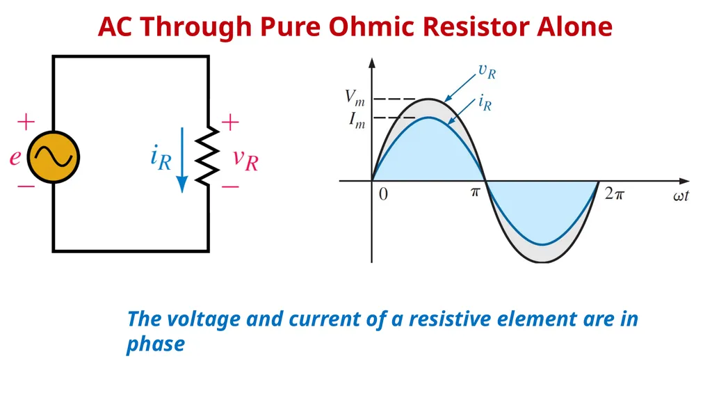
slide2. AC Through Pure Ohmic Resistor Alone The voltage and current of a resistive element are in phase<br>
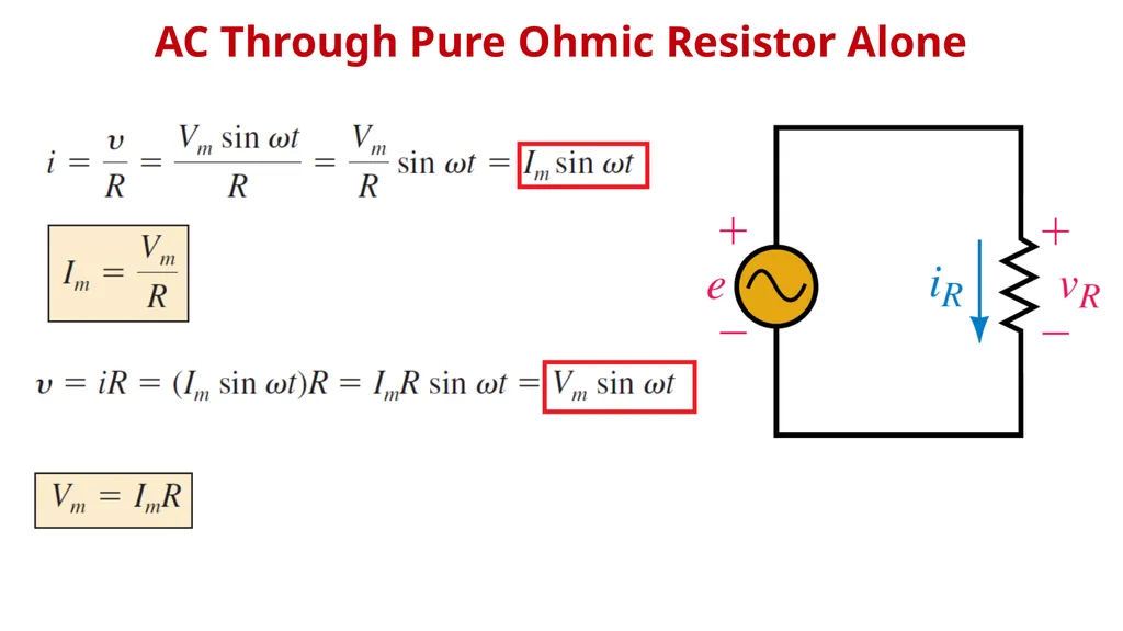
slide3. AC Through Pure Ohmic Resistor Alone<br>
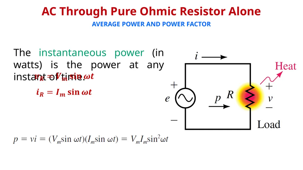
slide4. AC Through Pure Ohmic Resistor Alone AVERAGE POWER AND POWER FACTOR The instantaneous power (in watts) is the power at any instant of time.<br>
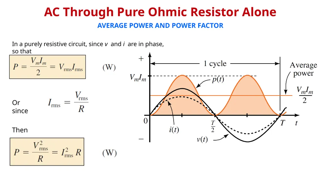
slide5. AC Through Pure Ohmic Resistor Alone AVERAGE POWER AND POWER FACTOR In a purely resistive circuit, since v and i are in phase, so that Or since Then<br>
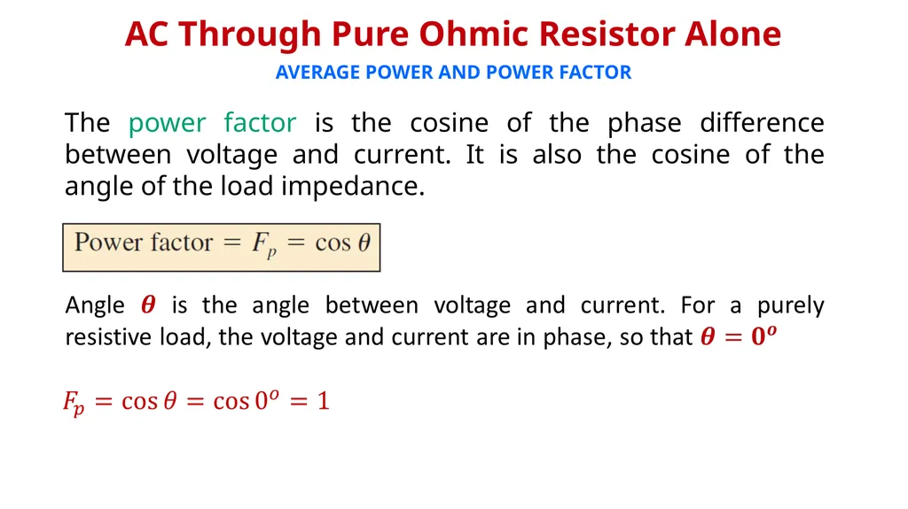
slide6. AC Through Pure Ohmic Resistor Alone AVERAGE POWER AND POWER FACTOR The power factor is the cosine of the phase difference between voltage and current. It is also the cosine of the angle of the load impedance.<br>
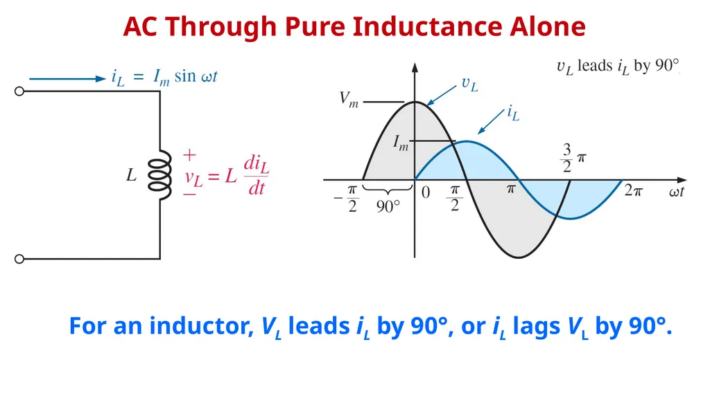
slide7. AC Through Pure Inductance Alone For an inductor, VL leads iL by 90°, or iL lags VL by 90°.<br>
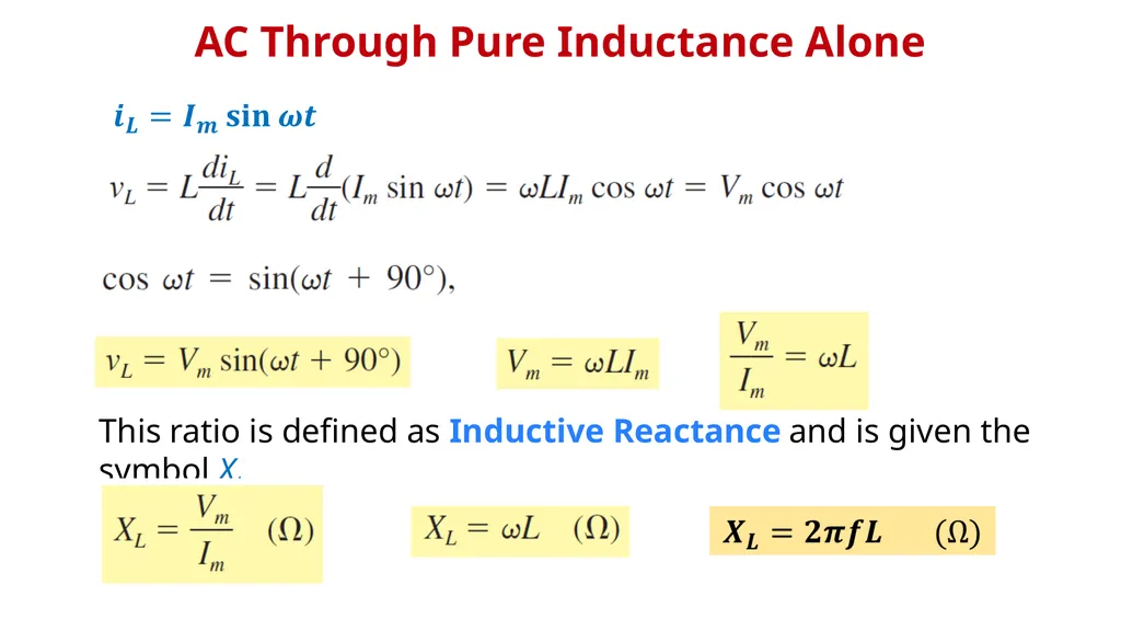
slide8. AC Through Pure Inductance Alone This ratio is defined as Inductive Reactance and is given the symbol XL<br>
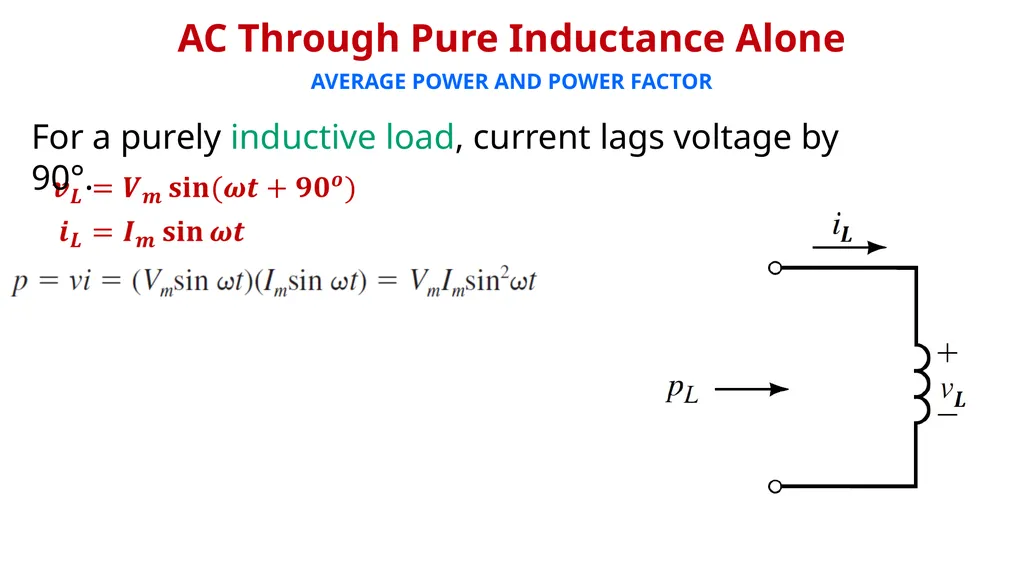
slide9. AVERAGE POWER AND POWER FACTOR AC Through Pure Inductance Alone For a purely inductive load, current lags voltage by 90°.<br>
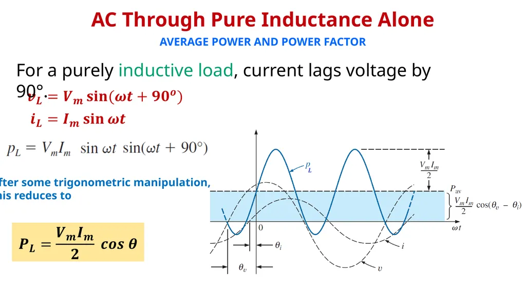
slide10. AVERAGE POWER AND POWER FACTOR AC Through Pure Inductance Alone After some trigonometric manipulation,
this reduces to For a purely inductive load, current lags voltage by 90°.<br>
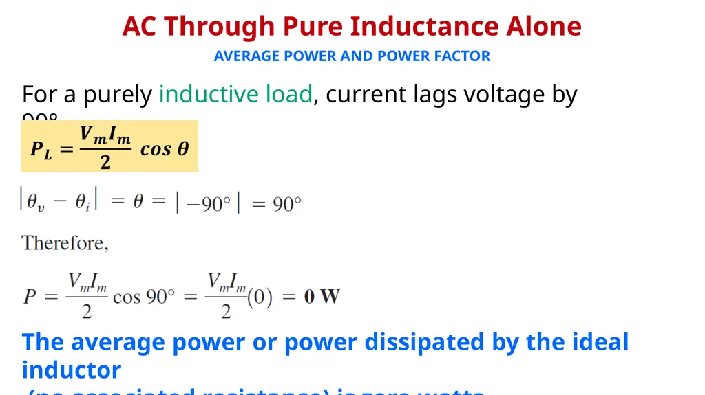
slide11. AVERAGE POWER AND POWER FACTOR AC Through Pure Inductance Alone For a purely inductive load, current lags voltage by 90°. The average power or power dissipated by the ideal inductor
(no associated resistance) is zero watts.<br>
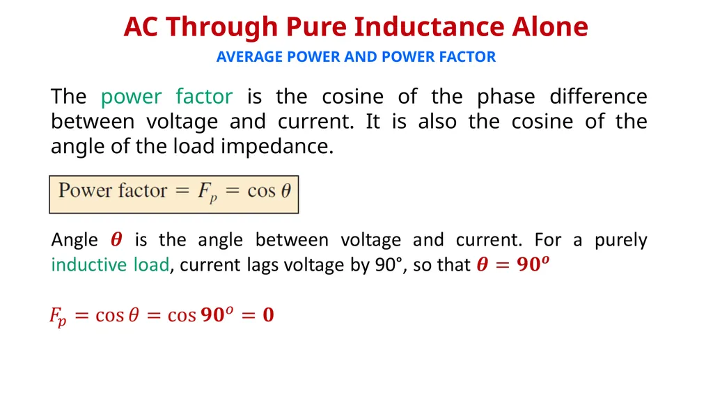
slide12. AVERAGE POWER AND POWER FACTOR The power factor is the cosine of the phase difference between voltage and current. It is also the cosine of the angle of the load impedance. AC Through Pure Inductance Alone<br>
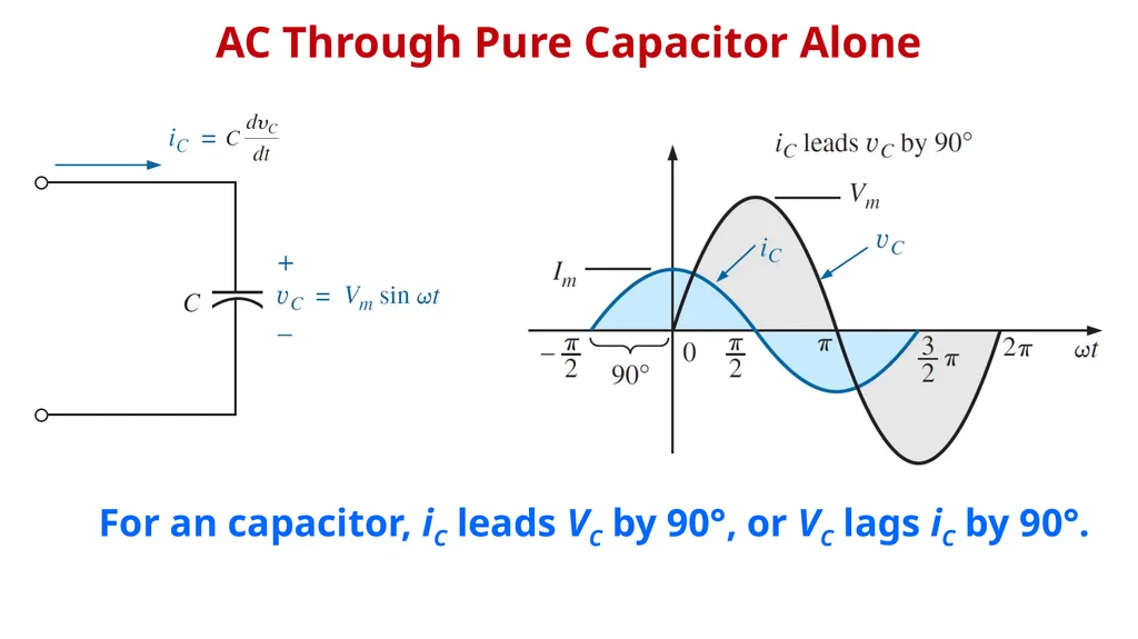
slide13. AC Through Pure Capacitor Alone For an capacitor, iC leads VC by 90°, or VC lags iC by 90°.<br>
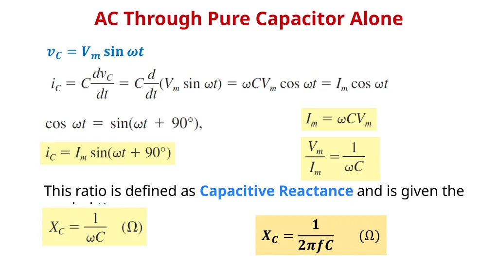
slide14. This ratio is defined as Capacitive Reactance and is given the symbol XC AC Through Pure Capacitor Alone<br>
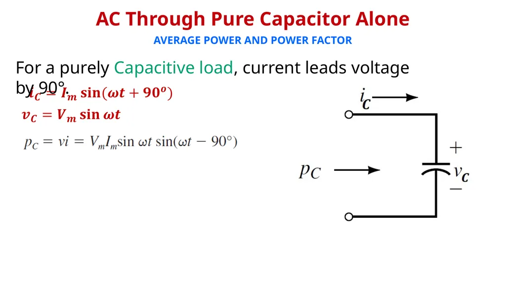
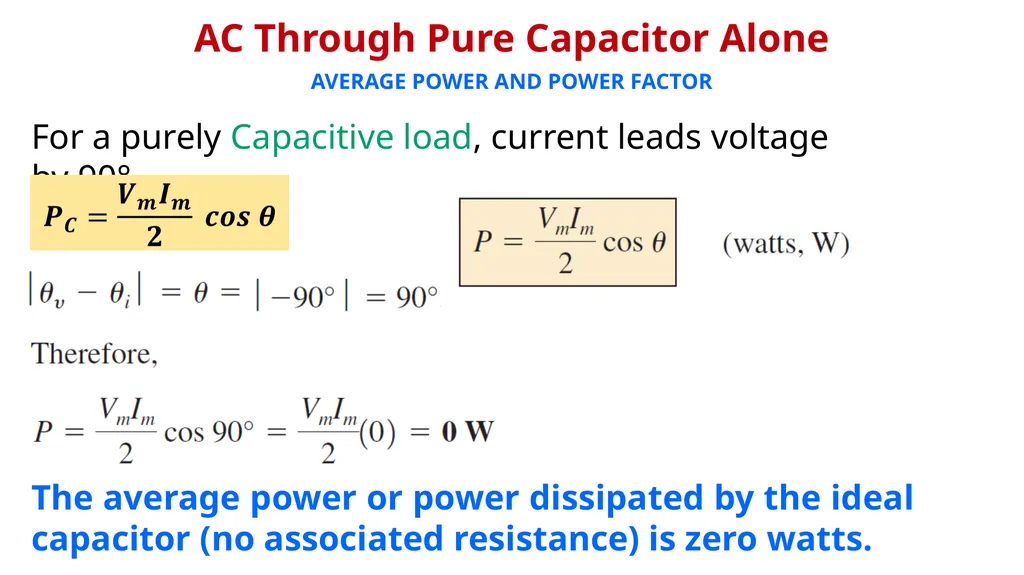
slide15. AVERAGE POWER AND POWER FACTOR For a purely Capacitive load, current leads voltage by 90°. AC Through Pure Capacitor Alone<br>
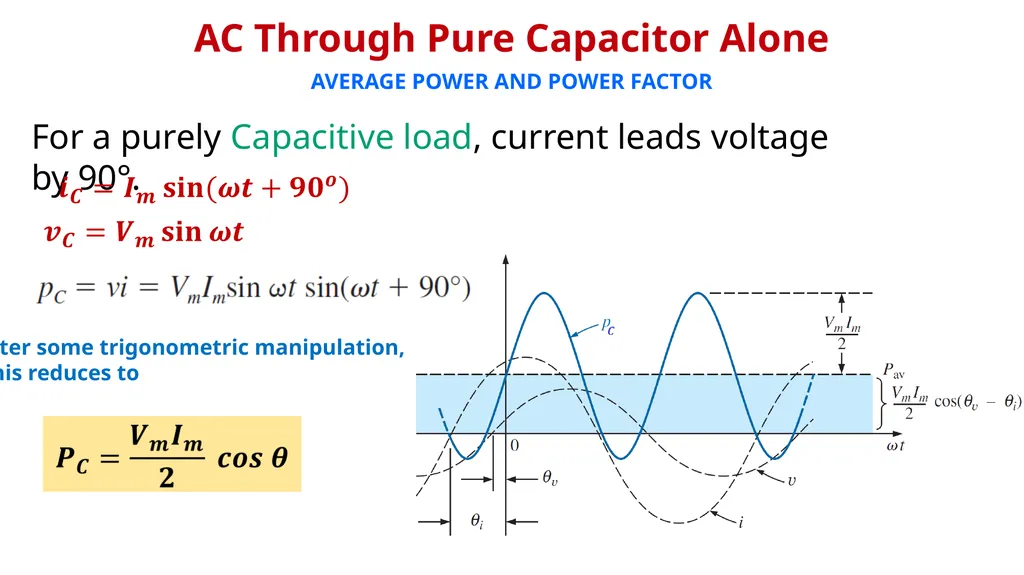
slide16. AVERAGE POWER AND POWER FACTOR After some trigonometric manipulation,
this reduces to For a purely Capacitive load, current leads voltage by 90°. AC Through Pure Capacitor Alone<br>
slide17. AVERAGE POWER AND POWER FACTOR For a purely Capacitive load, current leads voltage by 90°. The average power or power dissipated by the ideal capacitor (no associated resistance) is zero watts. AC Through Pure Capacitor Alone<br>
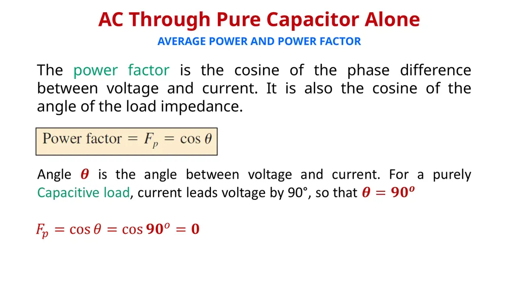
slide18. AVERAGE POWER AND POWER FACTOR The power factor is the cosine of the phase difference between voltage and current. It is also the cosine of the angle of the load impedance. AC Through Pure Capacitor Alone<br>
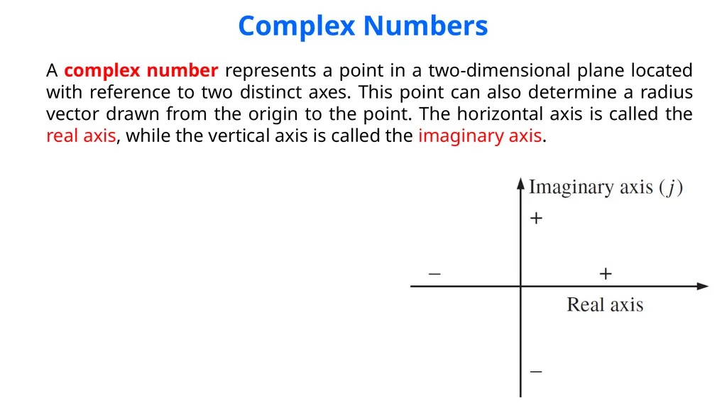
slide19. Complex Numbers A complex number represents a point in a two-dimensional plane located with reference to two distinct axes. This point can also determine a radius vector drawn from the origin to the point. The horizontal axis is called the real axis, while the vertical axis is called the imaginary axis.<br>
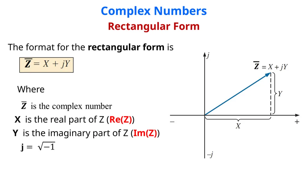
slide20. Complex Numbers Rectangular Form The format for the rectangular form is Where X is the real part of Z (Re(Z)) Y is the imaginary part of Z (Im(Z))<br>
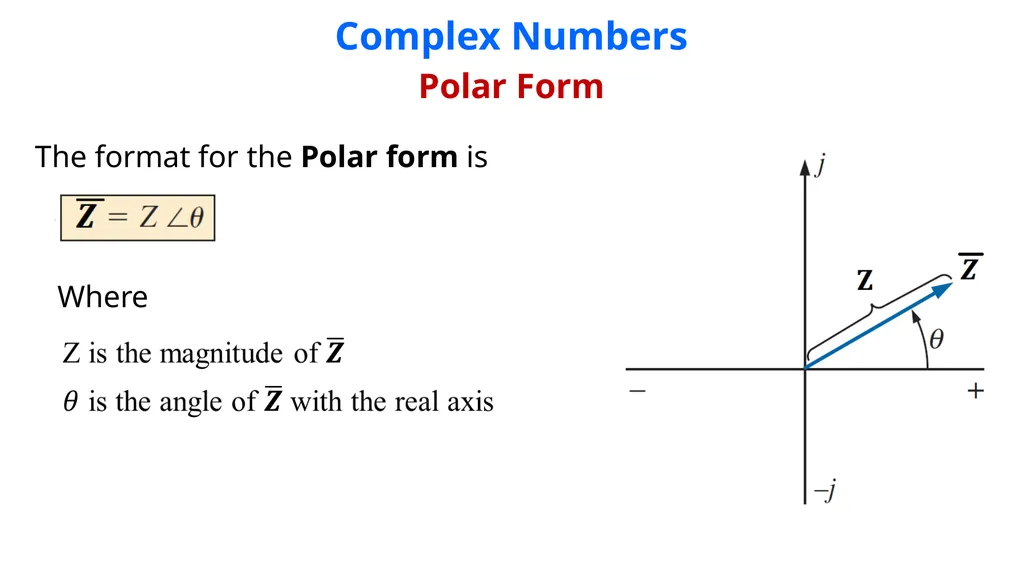
slide21. Complex Numbers Polar Form The format for the Polar form is Where<br>
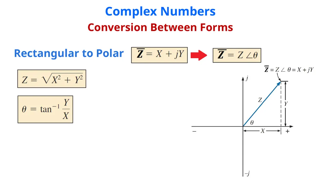
slide22. Complex Numbers Conversion Between Forms Rectangular to Polar<br>
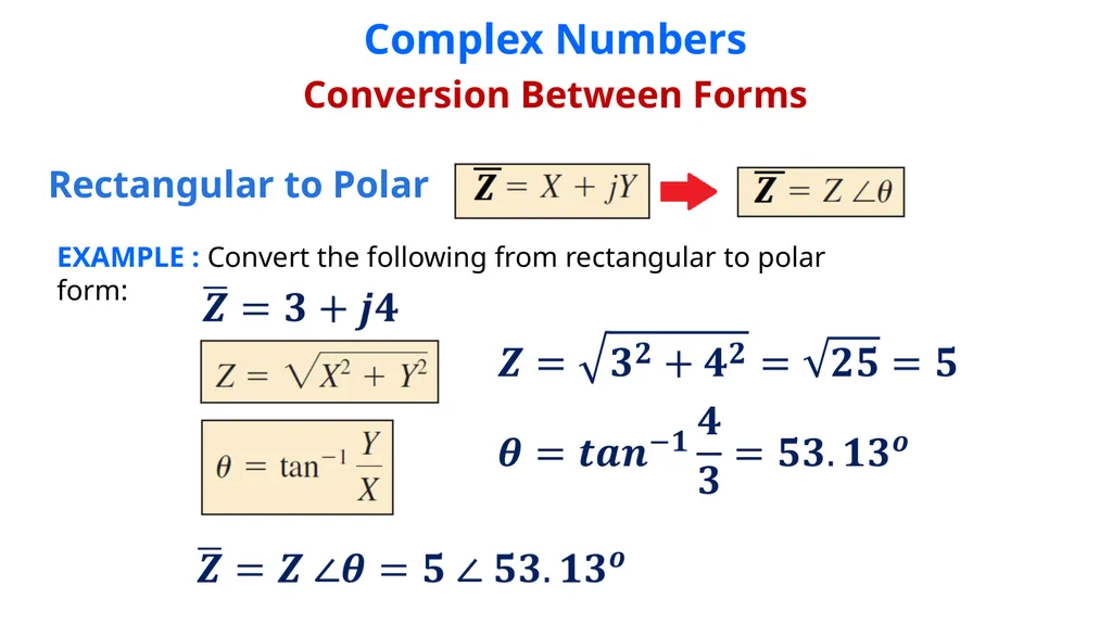
slide23. Complex Numbers Conversion Between Forms Rectangular to Polar EXAMPLE : Convert the following from rectangular to polar form:<br>
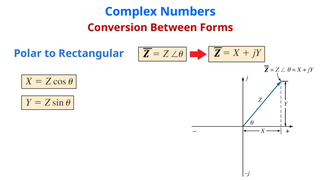
slide24. Complex Numbers Conversion Between Forms Polar to Rectangular<br>
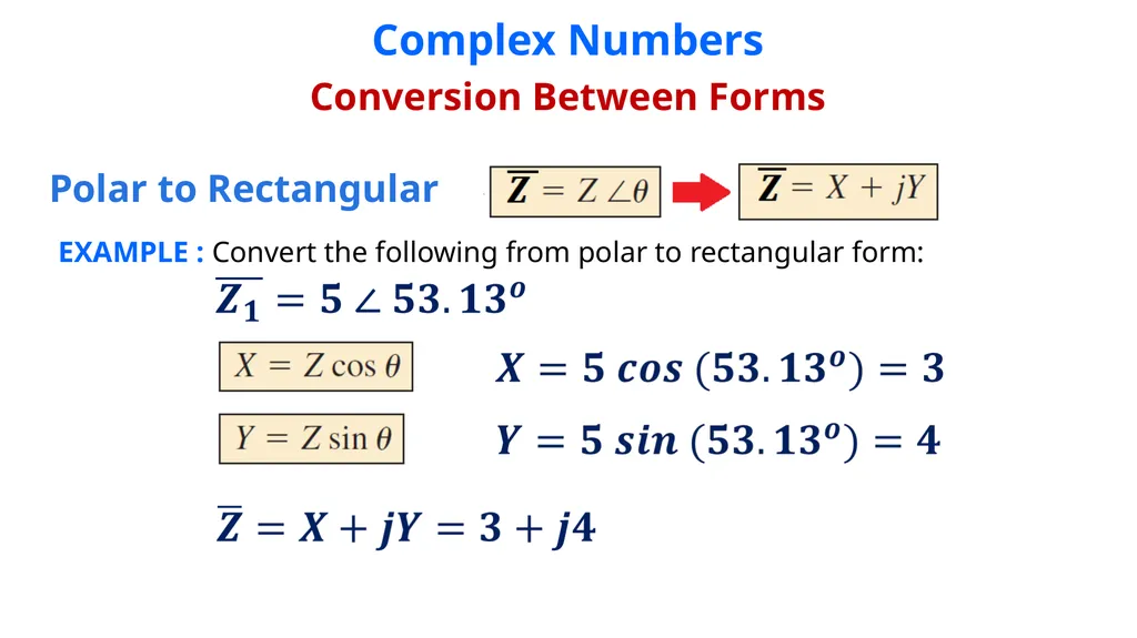
slide25. Complex Numbers Conversion Between Forms Polar to Rectangular EXAMPLE : Convert the following from polar to rectangular form:<br>
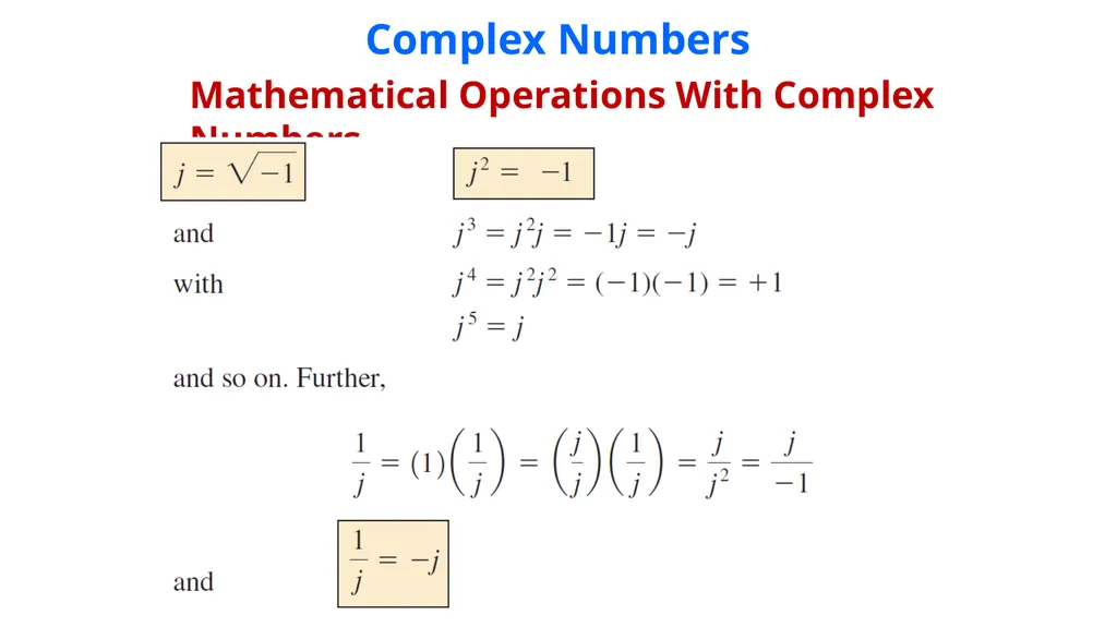
slide26. Complex Numbers Mathematical Operations With Complex Numbers<br>
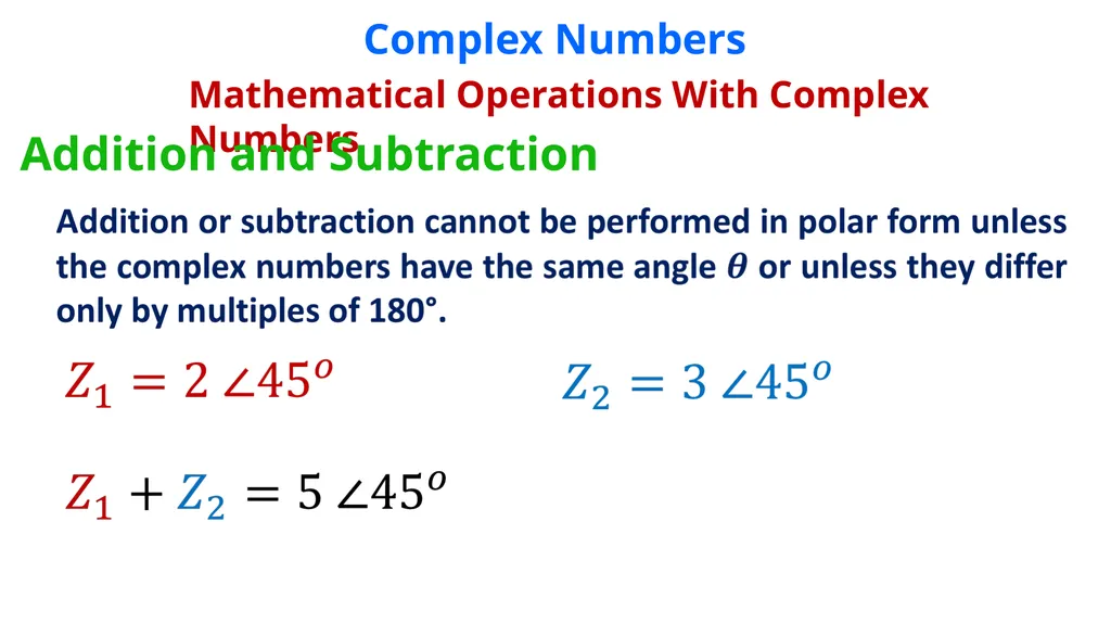
slide27. Complex Numbers Mathematical Operations With Complex Numbers Addition and Subtraction<br>
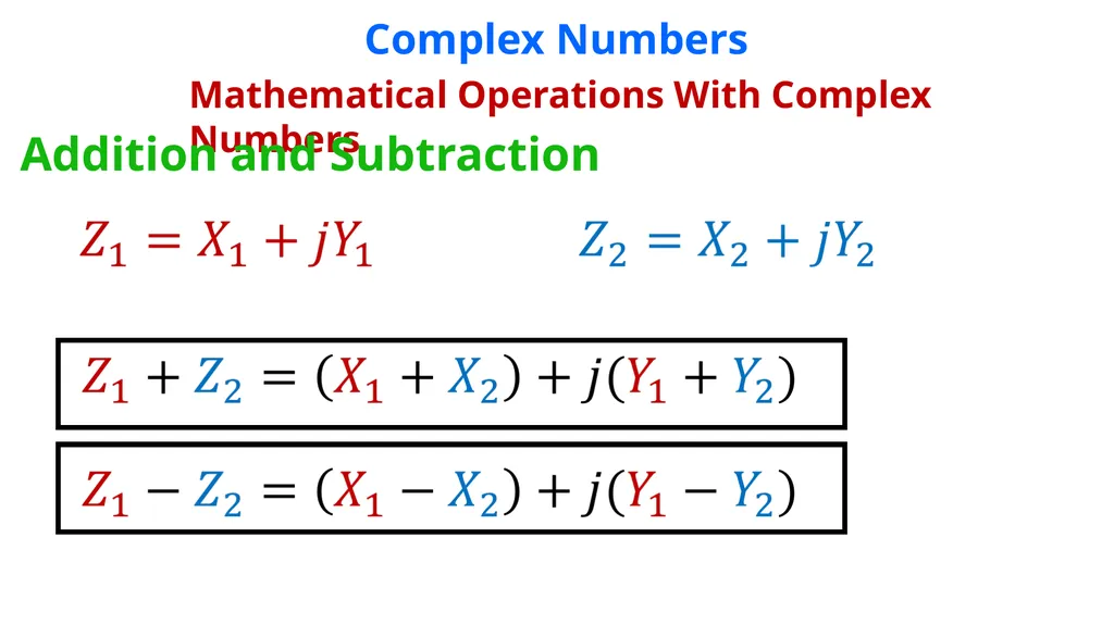
slide28. Complex Numbers Mathematical Operations With Complex Numbers Addition and Subtraction<br>
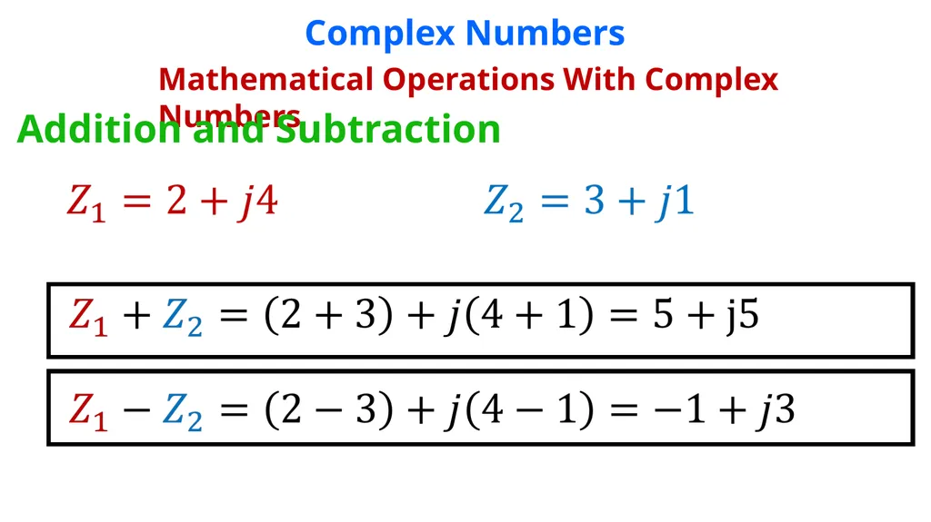
slide29. Complex Numbers Mathematical Operations With Complex Numbers Addition and Subtraction<br>
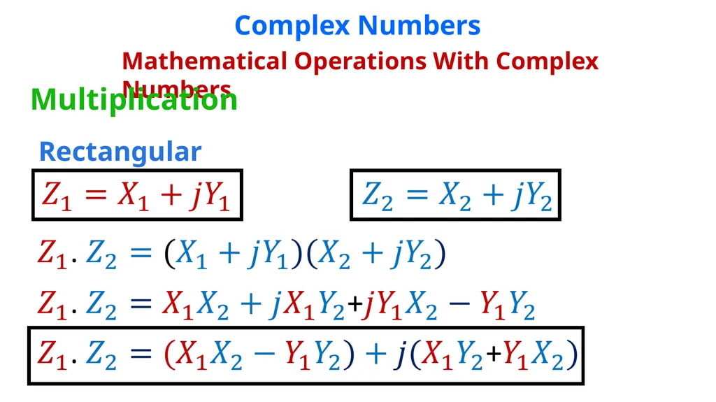
slide30. Complex Numbers Mathematical Operations With Complex Numbers Multiplication Rectangular<br>
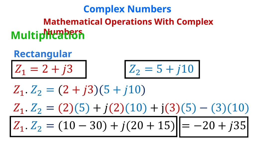
slide31. Complex Numbers Mathematical Operations With Complex Numbers Multiplication Rectangular<br>
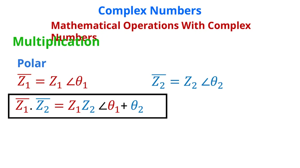
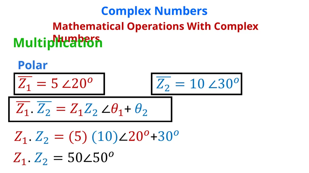
slide32. Complex Numbers Mathematical Operations With Complex Numbers Multiplication Polar<br>
slide33. Complex Numbers Mathematical Operations With Complex Numbers Multiplication Polar<br>
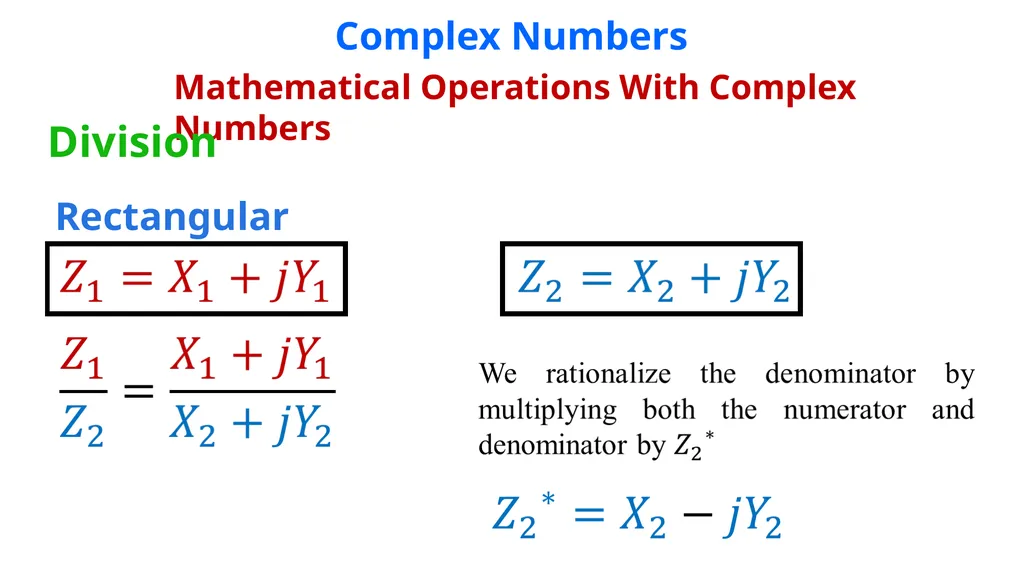
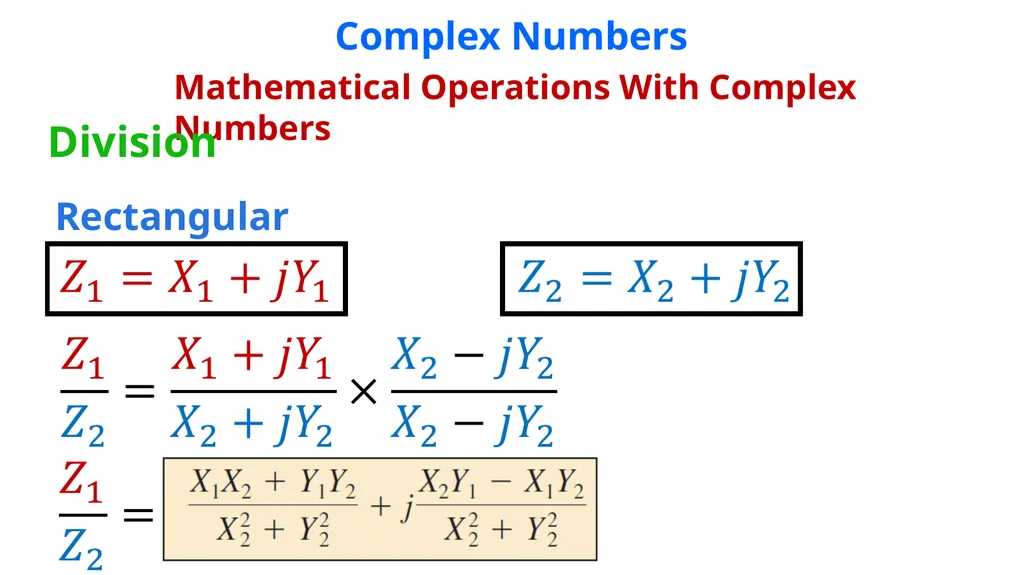
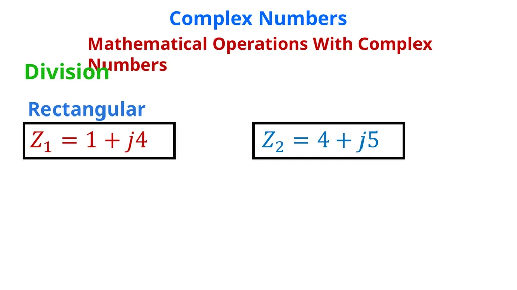
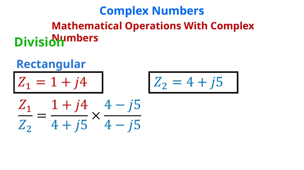
slide34. Complex Numbers Mathematical Operations With Complex Numbers Division Rectangular<br>
slide35. Complex Numbers Mathematical Operations With Complex Numbers Division Rectangular<br>
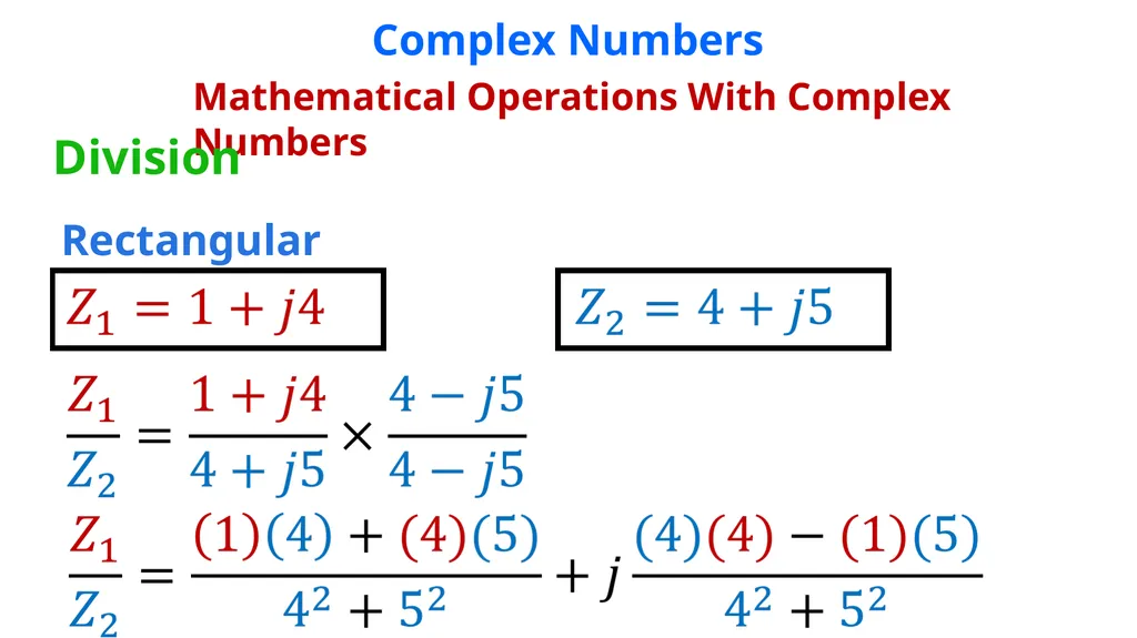
slide36. Complex Numbers Mathematical Operations With Complex Numbers Division Rectangular<br>
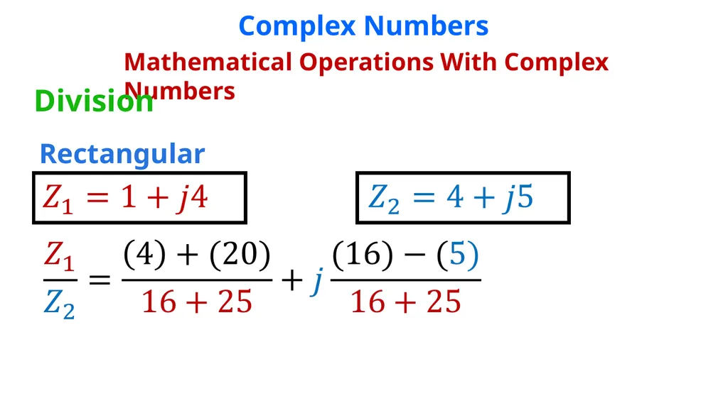
slide37. Complex Numbers Mathematical Operations With Complex Numbers Division Rectangular<br>
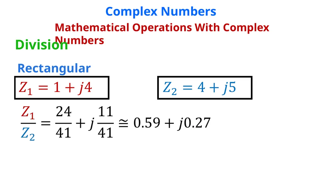
slide38. Complex Numbers Mathematical Operations With Complex Numbers Division Rectangular<br>
slide39. Complex Numbers Mathematical Operations With Complex Numbers Division Rectangular<br>
slide40. Complex Numbers Mathematical Operations With Complex Numbers Division Rectangular<br>
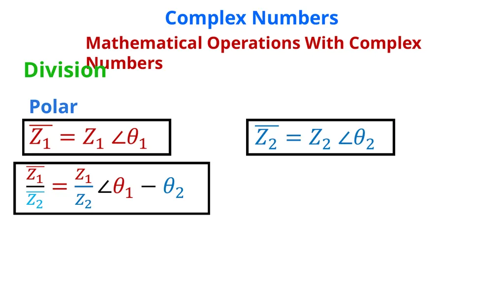
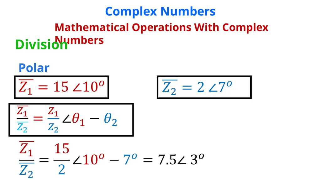
slide41. Complex Numbers Mathematical Operations With Complex Numbers Division Polar<br>
slide42. Complex Numbers Mathematical Operations With Complex Numbers Division Polar<br>
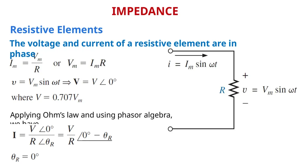
slide43. IMPEDANCE Resistive Elements The voltage and current of a resistive element are in phase Applying Ohm’s law and using phasor algebra, we have<br>
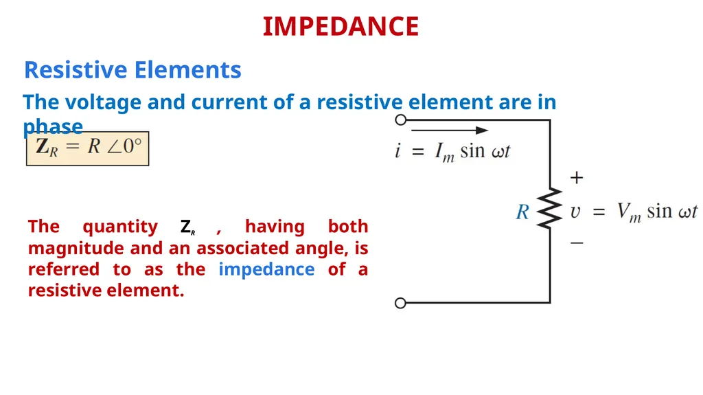
slide44. IMPEDANCE Resistive Elements The quantity ZR , having both magnitude and an associated angle, is referred to as the impedance of a resistive element. The voltage and current of a resistive element are in phase<br>
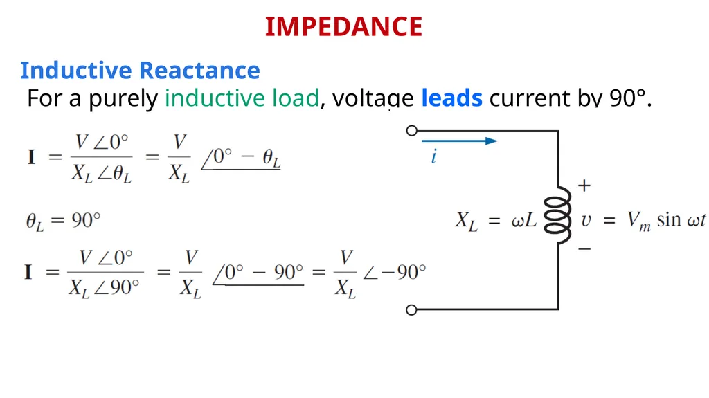
slide45. IMPEDANCE Inductive Reactance For a purely inductive load, voltage leads current by 90°.<br>
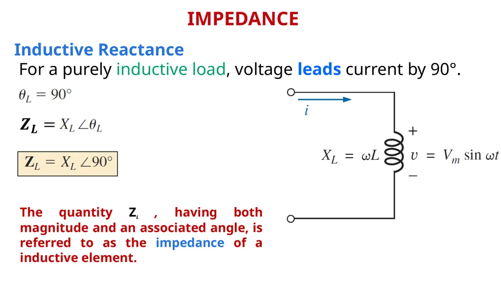
slide46. IMPEDANCE Inductive Reactance The quantity ZL , having both magnitude and an associated angle, is referred to as the impedance of a inductive element. For a purely inductive load, voltage leads current by 90°.<br>
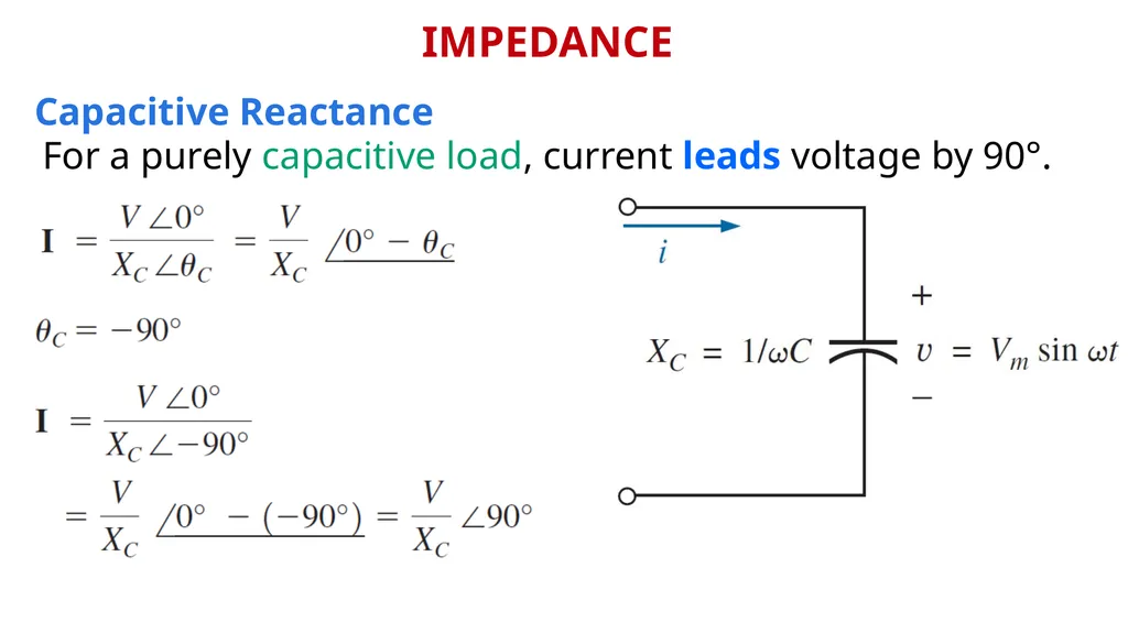
slide47. IMPEDANCE Capacitive Reactance For a purely capacitive load, current leads voltage by 90°.<br>
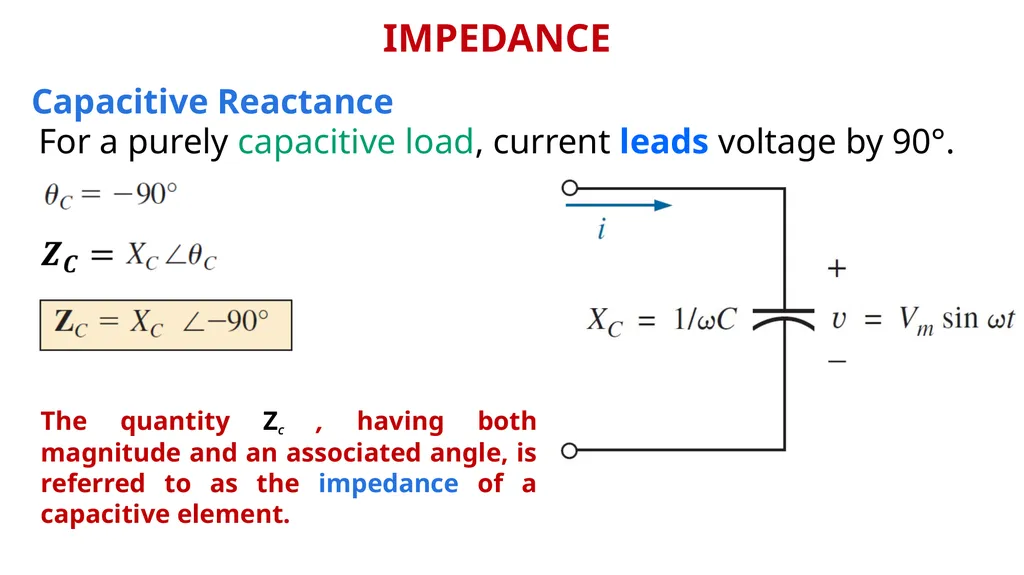
slide48. IMPEDANCE The quantity ZC , having both magnitude and an associated angle, is referred to as the impedance of a capacitive element. Capacitive Reactance For a purely capacitive load, current leads voltage by 90°.<br>
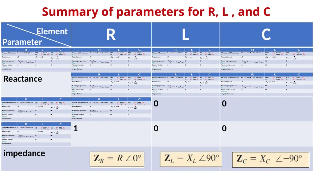
slide49. Summary of parameters for R, L , and C Element Parameter<br>
slide50. References Boylestad, Robert L. Introductory circuit analysis. Pearson Education, 2010. Robbins, Allan H., and Wilhelm C. Miller. Circuit analysis: Theory and practice. Cengage Learning, 2012. Sadiku, Matthew NO, and Chales K. Alexander. Fundamentals of electric circuits. McGraw-Hill Higher Education, 2007.<br>
slide2. AC Through Pure Ohmic Resistor Alone The voltage and current of a resistive element are in phase<br>
slide3. AC Through Pure Ohmic Resistor Alone<br>
slide4. AC Through Pure Ohmic Resistor Alone AVERAGE POWER AND POWER FACTOR The instantaneous power (in watts) is the power at any instant of time.<br>
slide5. AC Through Pure Ohmic Resistor Alone AVERAGE POWER AND POWER FACTOR In a purely resistive circuit, since v and i are in phase, so that Or since Then<br>
slide6. AC Through Pure Ohmic Resistor Alone AVERAGE POWER AND POWER FACTOR The power factor is the cosine of the phase difference between voltage and current. It is also the cosine of the angle of the load impedance.<br>
slide7. AC Through Pure Inductance Alone For an inductor, VL leads iL by 90°, or iL lags VL by 90°.<br>
slide8. AC Through Pure Inductance Alone This ratio is defined as Inductive Reactance and is given the symbol XL<br>
slide9. AVERAGE POWER AND POWER FACTOR AC Through Pure Inductance Alone For a purely inductive load, current lags voltage by 90°.<br>
slide10. AVERAGE POWER AND POWER FACTOR AC Through Pure Inductance Alone After some trigonometric manipulation,
this reduces to For a purely inductive load, current lags voltage by 90°.<br>
slide11. AVERAGE POWER AND POWER FACTOR AC Through Pure Inductance Alone For a purely inductive load, current lags voltage by 90°. The average power or power dissipated by the ideal inductor
(no associated resistance) is zero watts.<br>
slide12. AVERAGE POWER AND POWER FACTOR The power factor is the cosine of the phase difference between voltage and current. It is also the cosine of the angle of the load impedance. AC Through Pure Inductance Alone<br>
slide13. AC Through Pure Capacitor Alone For an capacitor, iC leads VC by 90°, or VC lags iC by 90°.<br>
slide14. This ratio is defined as Capacitive Reactance and is given the symbol XC AC Through Pure Capacitor Alone<br>
slide15. AVERAGE POWER AND POWER FACTOR For a purely Capacitive load, current leads voltage by 90°. AC Through Pure Capacitor Alone<br>
slide16. AVERAGE POWER AND POWER FACTOR After some trigonometric manipulation,
this reduces to For a purely Capacitive load, current leads voltage by 90°. AC Through Pure Capacitor Alone<br>
slide17. AVERAGE POWER AND POWER FACTOR For a purely Capacitive load, current leads voltage by 90°. The average power or power dissipated by the ideal capacitor (no associated resistance) is zero watts. AC Through Pure Capacitor Alone<br>
slide18. AVERAGE POWER AND POWER FACTOR The power factor is the cosine of the phase difference between voltage and current. It is also the cosine of the angle of the load impedance. AC Through Pure Capacitor Alone<br>
slide19. Complex Numbers A complex number represents a point in a two-dimensional plane located with reference to two distinct axes. This point can also determine a radius vector drawn from the origin to the point. The horizontal axis is called the real axis, while the vertical axis is called the imaginary axis.<br>
slide20. Complex Numbers Rectangular Form The format for the rectangular form is Where X is the real part of Z (Re(Z)) Y is the imaginary part of Z (Im(Z))<br>
slide21. Complex Numbers Polar Form The format for the Polar form is Where<br>
slide22. Complex Numbers Conversion Between Forms Rectangular to Polar<br>
slide23. Complex Numbers Conversion Between Forms Rectangular to Polar EXAMPLE : Convert the following from rectangular to polar form:<br>
slide24. Complex Numbers Conversion Between Forms Polar to Rectangular<br>
slide25. Complex Numbers Conversion Between Forms Polar to Rectangular EXAMPLE : Convert the following from polar to rectangular form:<br>
slide26. Complex Numbers Mathematical Operations With Complex Numbers<br>
slide27. Complex Numbers Mathematical Operations With Complex Numbers Addition and Subtraction<br>
slide28. Complex Numbers Mathematical Operations With Complex Numbers Addition and Subtraction<br>
slide29. Complex Numbers Mathematical Operations With Complex Numbers Addition and Subtraction<br>
slide30. Complex Numbers Mathematical Operations With Complex Numbers Multiplication Rectangular<br>
slide31. Complex Numbers Mathematical Operations With Complex Numbers Multiplication Rectangular<br>
slide32. Complex Numbers Mathematical Operations With Complex Numbers Multiplication Polar<br>
slide33. Complex Numbers Mathematical Operations With Complex Numbers Multiplication Polar<br>
slide34. Complex Numbers Mathematical Operations With Complex Numbers Division Rectangular<br>
slide35. Complex Numbers Mathematical Operations With Complex Numbers Division Rectangular<br>
slide36. Complex Numbers Mathematical Operations With Complex Numbers Division Rectangular<br>
slide37. Complex Numbers Mathematical Operations With Complex Numbers Division Rectangular<br>
slide38. Complex Numbers Mathematical Operations With Complex Numbers Division Rectangular<br>
slide39. Complex Numbers Mathematical Operations With Complex Numbers Division Rectangular<br>
slide40. Complex Numbers Mathematical Operations With Complex Numbers Division Rectangular<br>
slide41. Complex Numbers Mathematical Operations With Complex Numbers Division Polar<br>
slide42. Complex Numbers Mathematical Operations With Complex Numbers Division Polar<br>
slide43. IMPEDANCE Resistive Elements The voltage and current of a resistive element are in phase Applying Ohm’s law and using phasor algebra, we have<br>
slide44. IMPEDANCE Resistive Elements The quantity ZR , having both magnitude and an associated angle, is referred to as the impedance of a resistive element. The voltage and current of a resistive element are in phase<br>
slide45. IMPEDANCE Inductive Reactance For a purely inductive load, voltage leads current by 90°.<br>
slide46. IMPEDANCE Inductive Reactance The quantity ZL , having both magnitude and an associated angle, is referred to as the impedance of a inductive element. For a purely inductive load, voltage leads current by 90°.<br>
slide47. IMPEDANCE Capacitive Reactance For a purely capacitive load, current leads voltage by 90°.<br>
slide48. IMPEDANCE The quantity ZC , having both magnitude and an associated angle, is referred to as the impedance of a capacitive element. Capacitive Reactance For a purely capacitive load, current leads voltage by 90°.<br>
slide49. Summary of parameters for R, L , and C Element Parameter<br>
slide50. References Boylestad, Robert L. Introductory circuit analysis. Pearson Education, 2010. Robbins, Allan H., and Wilhelm C. Miller. Circuit analysis: Theory and practice. Cengage Learning, 2012. Sadiku, Matthew NO, and Chales K. Alexander. Fundamentals of electric circuits. McGraw-Hill Higher Education, 2007.<br>