Chapter 2 Network topology and Networking devices Network Topology Geographical representation of the links. Topology is physical layout of computers, cables and other connected devices on a network. Types Physical Topology Logical Topology
"Chapter 2 Network topology and Networking devices" is the property of its rightful owner. Permission is granted to
download and print the materials on this website for personal, non-commercial use only, and to display it
on your personal computer provided you do not modify the materials and that you retain all copyright
notices contained in the materials. By downloading content from our website, you accept the terms of this
agreement.
Presentation Transcript
01
Chapter 2 Network topology and Networking devices<br>
02
Network Topology Geographical representation of the links.
Topology is physical layout of computers, cables and other connected devices on a network.
Types
Physical Topology
Logical Topology<br>
03
Types of Topology Physical Topology:
actual layout of the computer cables and other network devices.
Logical Topology:
the way in which the network appears to the devices that use it.
Refers to how data is actually transferred in a network.<br>
04
Selection Criteria Size ( no of node) of the system.
Cost of the components and service required.
Management of network.
Architecture of network.
Cable type.
Expandability of the network.
The desired performance.
Reliability.<br>
05
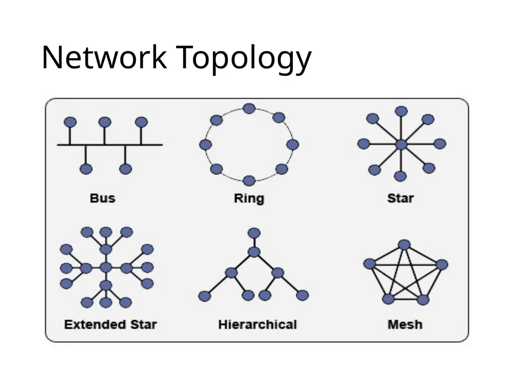
Types of Network Topology Here, some logical layout of topology.
Bus
Ring
Star
Mesh
Tree and Hybrid<br>
06
Bus Topology<br>
07
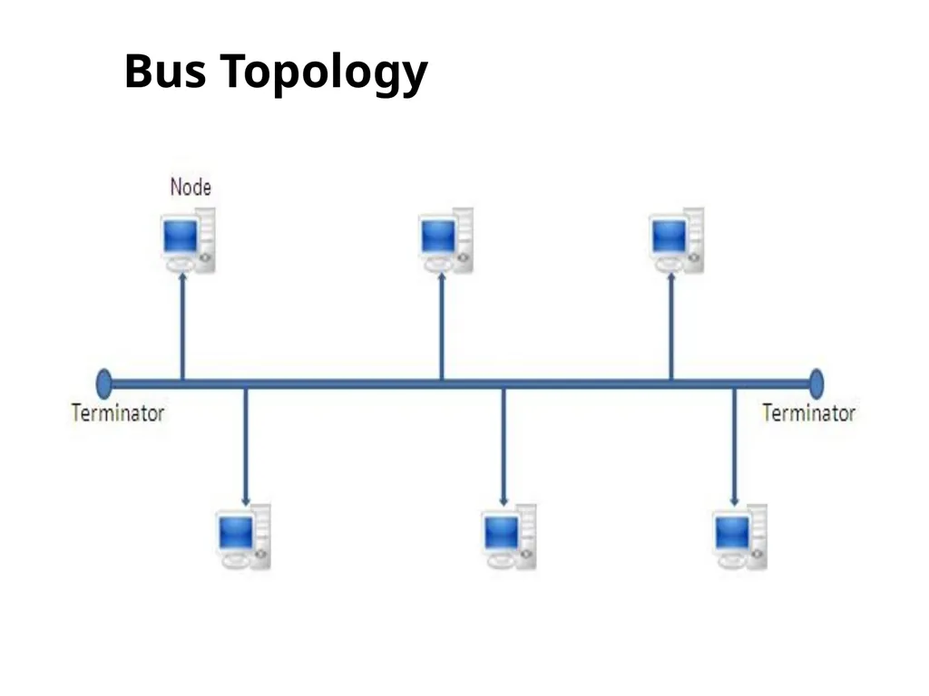
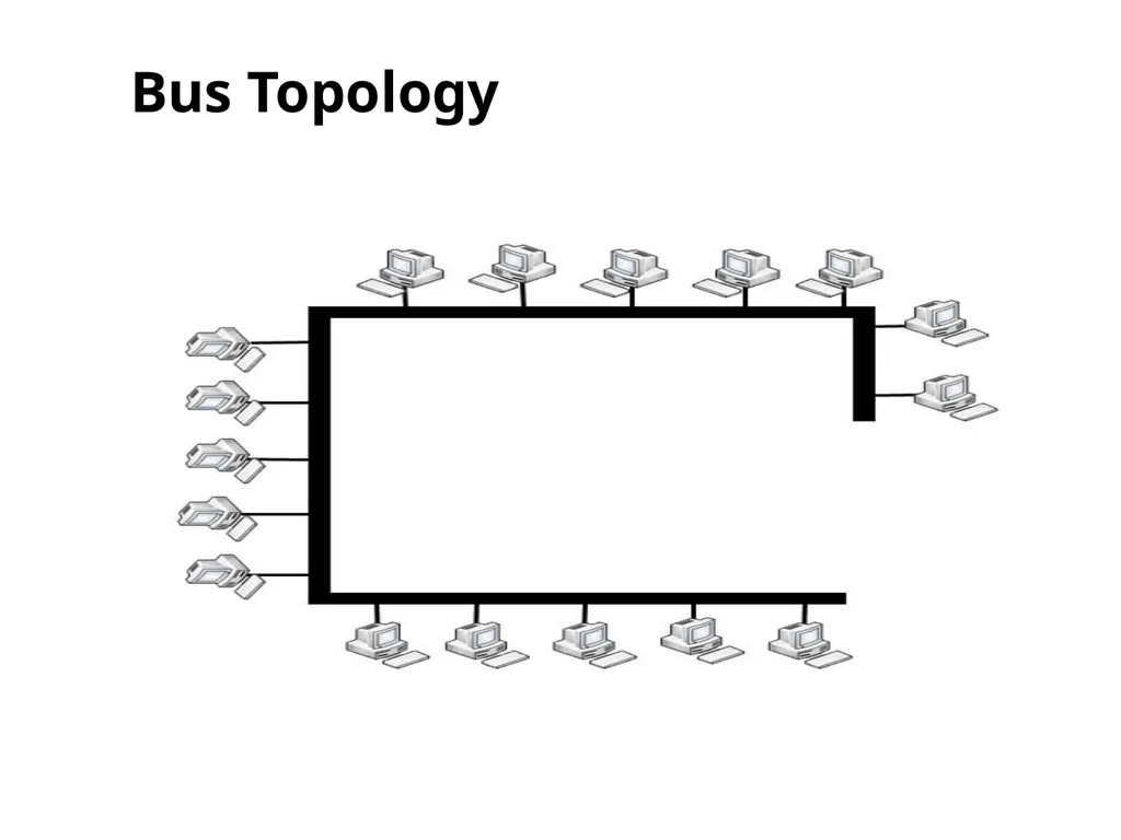
Bus Topology Also called as Linear topology.
A bus topology is multipoint.
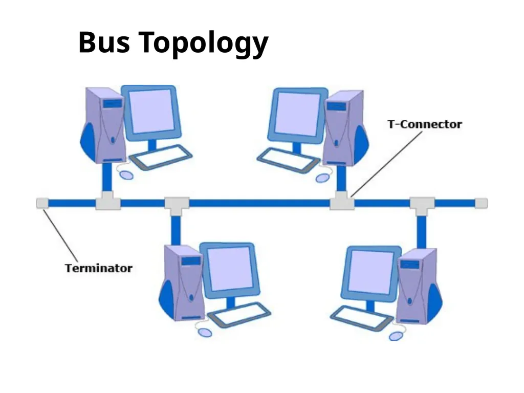
Here one long cable act as a backbone to link all the devices.
Devices are connected to the backbone by drop lines and taps.
Drop line- is the connection b/w the devices and the cable.
Tap- is the splitter that cut the main link.
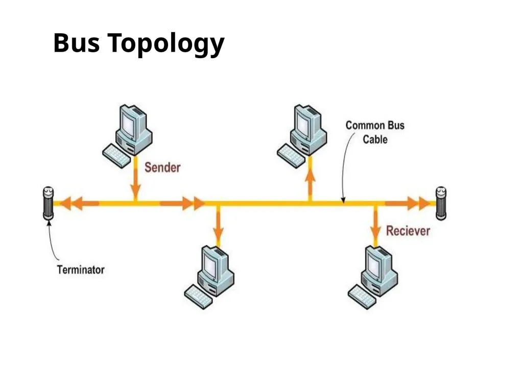
This allows only one device to transmit at a time.<br>
08
Bus Topology<br>
09
Bus Topology<br>
10
Bus Topology<br>
11
Bus Topology If a device want to communicate with other device on the n/w, sends a broadcast message onto the wire all other devices receive the message.
But only the intended devices accepts and process the message.
Bus is passive topology.
Bus Topology
Bus Failure<br>
12
Bus Topology Advantages:
Ease of installation
Less cabling
Suitable for temporary and small networks.
Disadvantages:
Difficult reconfiguration and fault isolation.
Difficult to add new devices.
Signal reflection at top can degradation in quality.
If any fault in backbone can stops all transmission.
Only one computer can transmit at a time.
Limited cable length and number of stations.<br>
13
Bus Topology Application:
Most computer motherboard.<br>
14
Ring Topology<br>
15
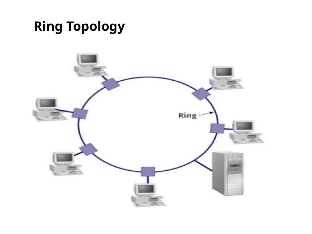
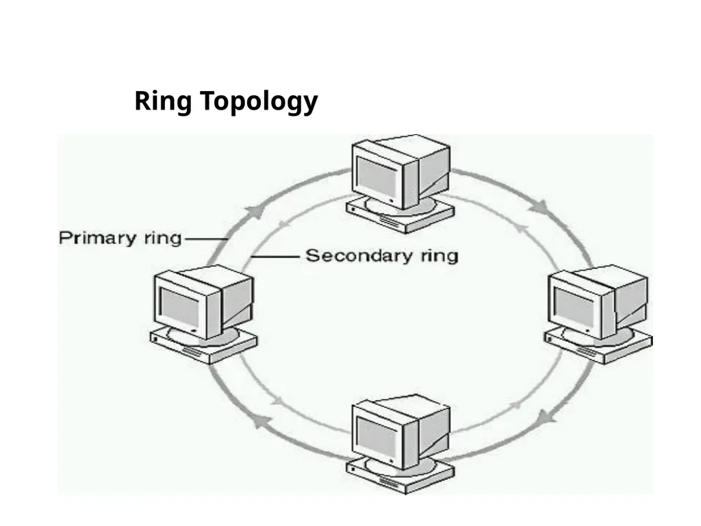
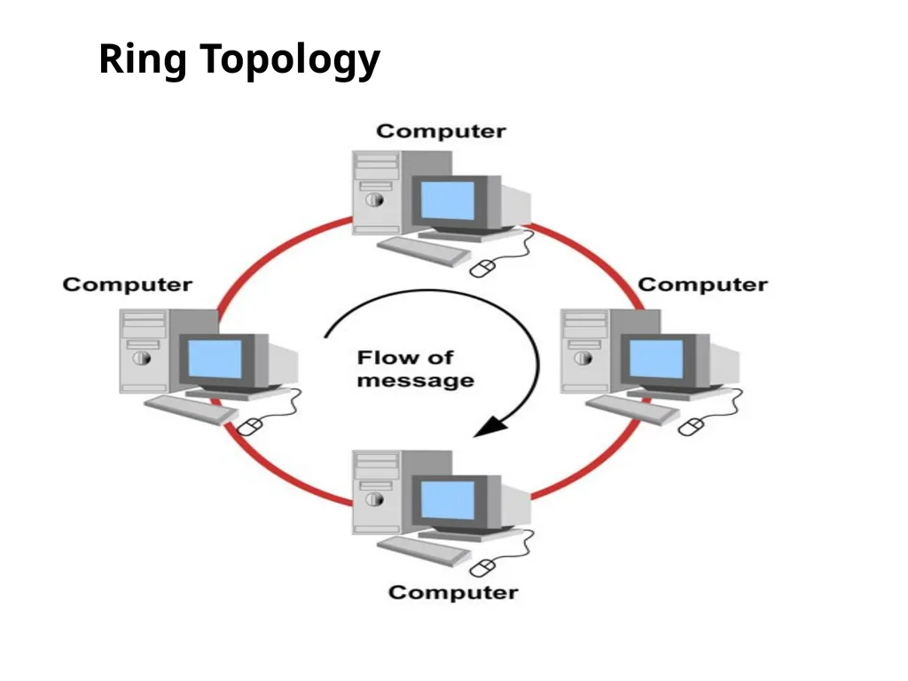
Ring Topology In Ring topology each node is connected to the two nearest nodes so the entire network forms a circle.
The signal is passed in one direction from one device to another device until it reaches the destination.
Ring is the Active Network, because each computer retransmits what is receives from previous computer.
To add or delete a device requires changing only two connections. Ring Topology Token ring Failures<br>
16
Ring Topology<br>
17
Ring Topology<br>
18
Token Ring Topology Variation of Ring Topology.
Token passing
Token Ring<br>
19
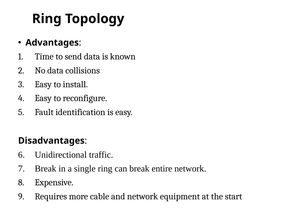
Ring Topology Advantages:
Time to send data is known
No data collisions
Easy to install.
Easy to reconfigure.
Fault identification is easy.
Disadvantages:
Unidirectional traffic.
Break in a single ring can break entire network.
Expensive.
Requires more cable and network equipment at the start<br>
20
Ring Topology Applications:
Ring topologies are found in some office buildings or school campuses.
Today high speed LANs made this topology less popular.<br>
21
Star Topology<br>
22
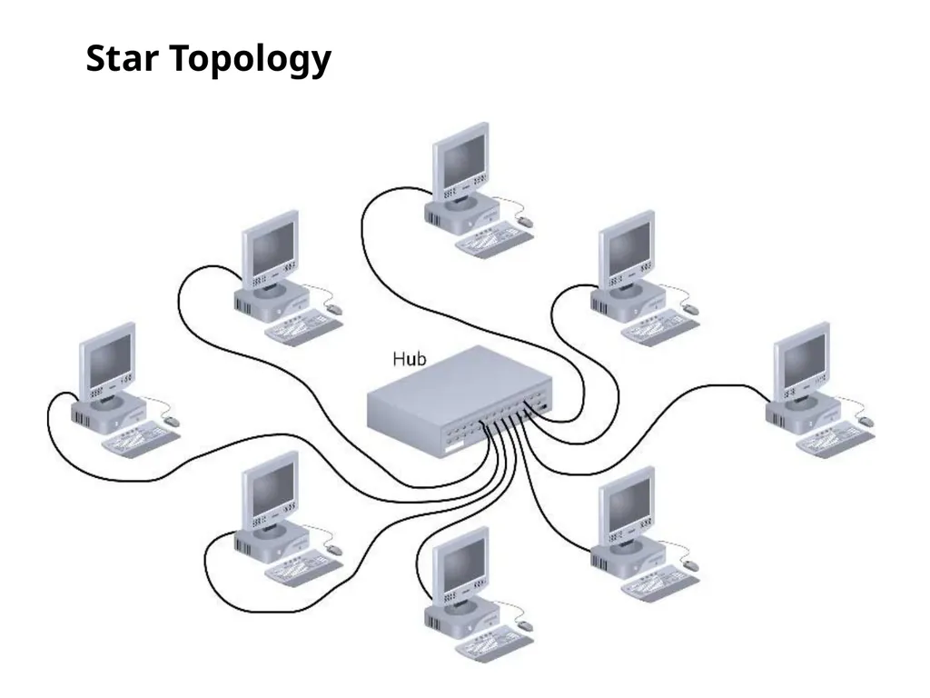
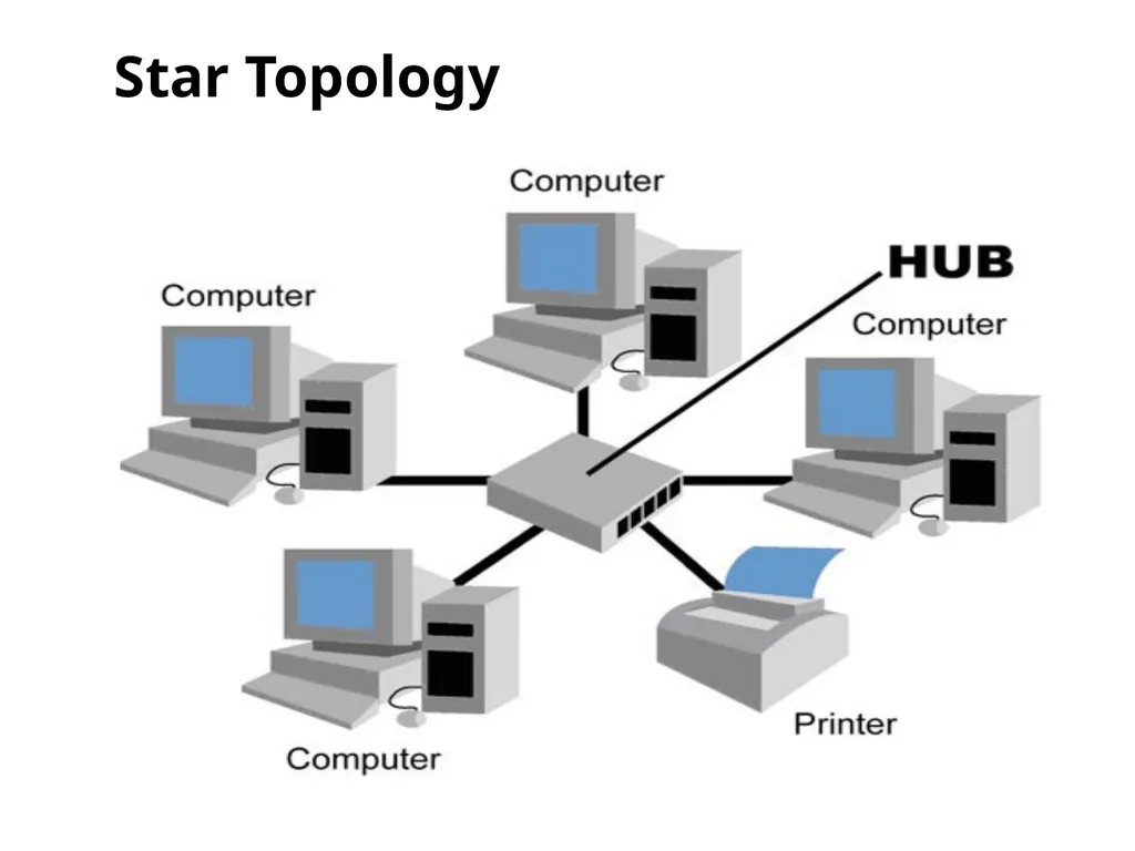
Star Topology Here each device has a dedicated point-to-point link to the central controller called “Hub”(Act as a Exchange).
There is no direct traffic between devices.
The transmission are occur only through the central “hub”.
When device one wants to send data to device 2; First sends the data to hub. Which then relays the data to the other connected device. Star Topology<br>
23
Star Topology<br>
24
Star Topology Advantages:
Good option for modern networks.
Low setup costs.
Installation, management and configuration is easy.
Less cabling is needed.
Robustness.(if one link fails, only that links is affected. All other links remain active)
Easy to fault identification & to remove parts.
Scalable: No distruptions to the network when connecting(or) removing devices.<br>
25
Star Topology Disadvantages:
Requires more cable than the bus
Dependency: Hub is a single point of failure. When it goes down. The whole system is dead.<br>
26
Applications Star topology used in Local Area Networks (LANs).
High speed LAN often use STAR.<br>
27
Mesh Topology<br>
28
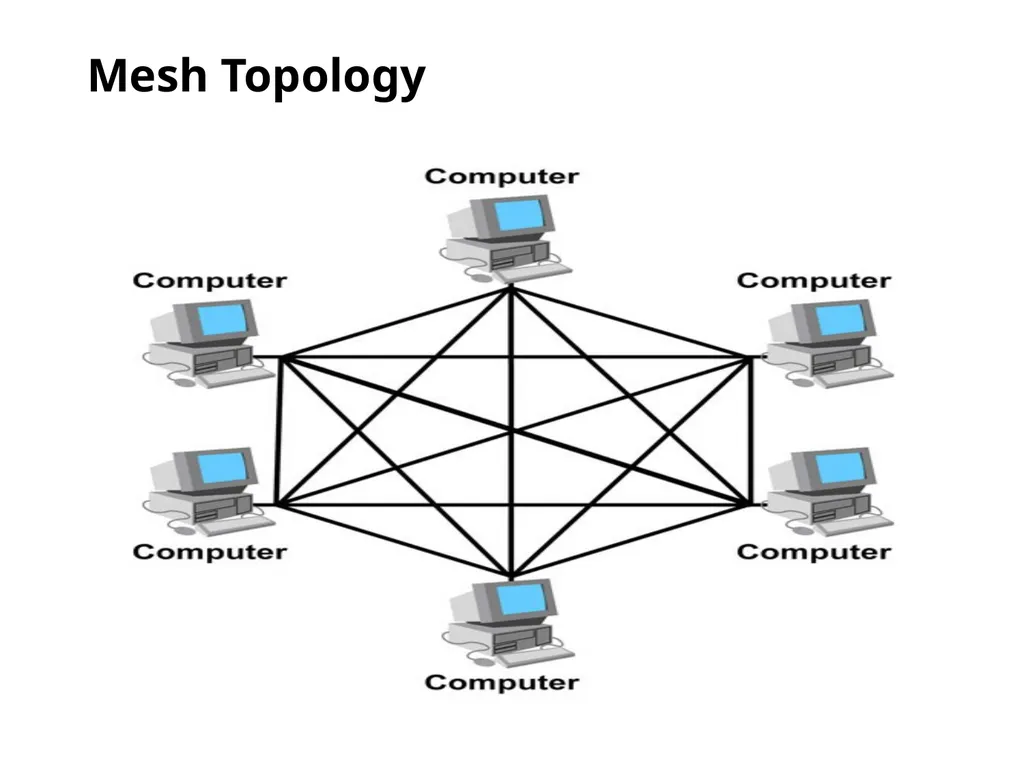
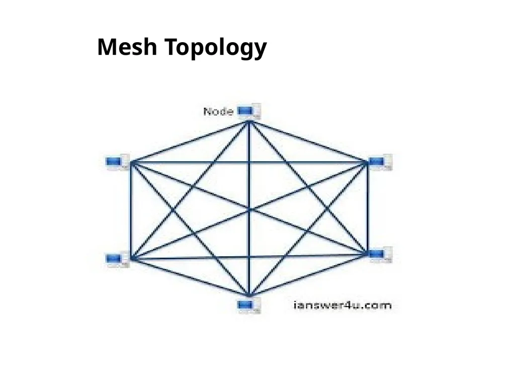
Mesh Topology Here every device has a point to point link to every other device.
Node-1 must be connected with n-1 nodes.
A fully connected mesh can have n(n-1)/2 physical channels to link n devices.
It must have n-1 i/o ports.<br>
29
Mesh Topology Advantages:
They use dedicated links so each link can only carry its own data load. So traffic problem can be avoided.
It is robust. If any one link get damaged it cannot affect others.
It gives privacy and security.(Message travels along a dedicated link)
Fault identification and fault isolation are easy.<br>
30
Mesh Topology<br>
31
Mesh Topology Disadvantages:
Cabling cost is high: The cabling and I/O ports required are more, since every device is connected to each devices through dedicated link.
Wiring is very complicated
Hardware required to connected each device is highly expensive.
Troubleshooting a failed cable is tricky<br>
32
Mesh Topology Applications:
Telephone Regional office.
WAN.(Wide Area Network).<br>
33
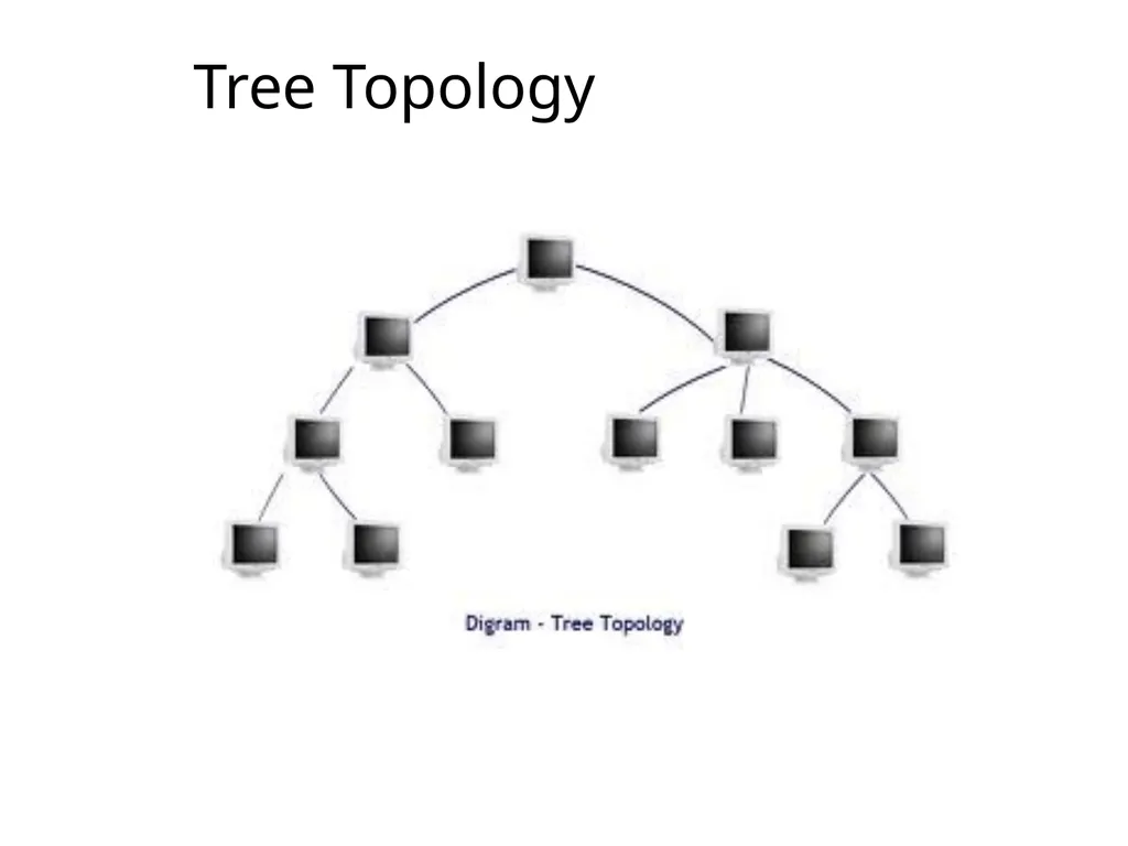
Tree Topology Alternatively referred to as a star bus topology.
Tree topology is one of the most common network setups that is similar to a bus topology and a star topology.
A tree topology connects multiple star networks to other star networks.<br>
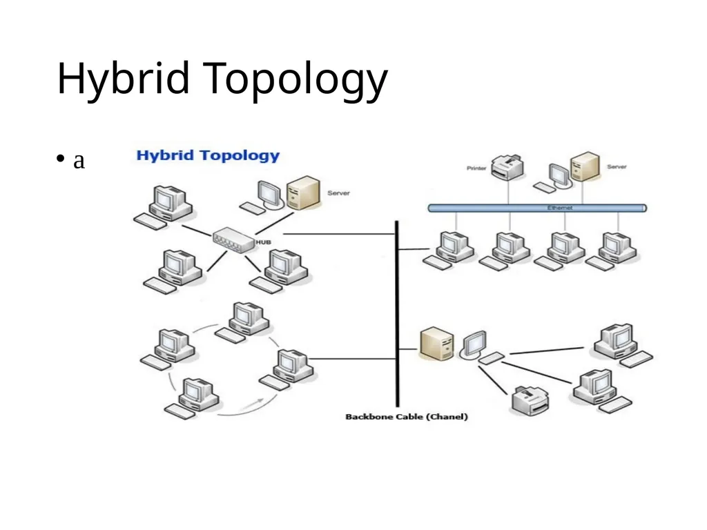
Hybrid Topology A network which contain all type of physical structure and connected under a single backbone channel.<br>
37
Hybrid Topology a<br>
38
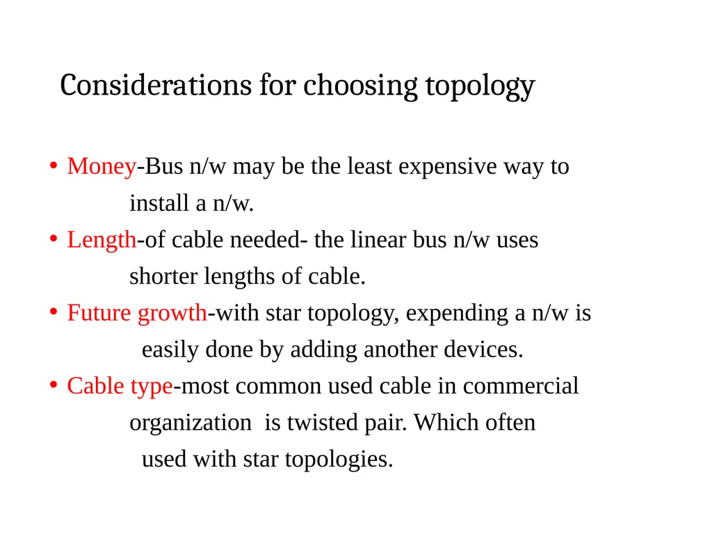
Considerations for choosing topology Money-Bus n/w may be the least expensive way to
install a n/w.
Length-of cable needed- the linear bus n/w uses
shorter lengths of cable.
Future growth-with star topology, expending a n/w is
easily done by adding another devices.
Cable type-most common used cable in commercial
organization is twisted pair. Which often
used with star topologies.<br>
39
Full mesh topology is theoretically the best since every device is connected to every other device.(thus maximizing speed and security. however, it quite expensive to install)
Next best would be tree topology, which is basically a connection of star and bus.<br>