
Chapter 5: The Fire Pump Knowledge Objectives

Description: Chapter 5: The Fire Pump Knowledge Objectives Explain the importance of understanding the fire pump and its systems. Describe the exterior and interior features of a pumper. Define the term pump. Explain the basic operations of
Related Topics
Download Presentation
"Chapter 5: The Fire Pump Knowledge Objectives" is the property of its rightful owner. Permission is granted to download and print the materials on this website for personal, non-commercial use only, and to display it on your personal computer provided you do not modify the materials and that you retain all copyright notices contained in the materials. By downloading content from our website, you accept the terms of this agreement.
Presentation Transcript
slide1. Chapter 5: The Fire Pump<br>
slide2. Knowledge Objectives Explain the importance of understanding the fire pump and its systems.
Describe the exterior and interior features of a pumper.
Define the term pump.
Explain the basic operations of positive-displacement pumps and centrifugal pumps.
Explain the different types of positive-displacement pumps.<br>
slide3. Knowledge Objectives Explain the different types of centrifugal pumps.
Describe a single-stage pump and a two-stage pump.
Describe the intake side of the fire pump.
Describe the discharge sides of a pump.
Describe the pump valves and drains.
Describe the components of the pump panel.<br>
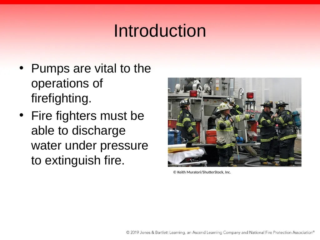
slide4. Introduction Pumps are vital to the operations of firefighting.
Fire fighters must be able to discharge water under pressure to extinguish fire. © Keith Muratori/ShutterStock, Inc.<br>
slide5. Introduction The driver/operator must understand how pumps operate in order to fix any problems they may encounter on the fireground.
“Don’t just be a knob puller—know what you are doing.”
Ensure that you have a thorough understanding of how each pump operates.<br>
slide6. Exterior of the Fire Department Pumper A large fire pump with hose and tools used to extinguish fires
Most common fire apparatus
Compartments hold various tools and equipment.
Ground ladders may be mounted on the side of the apparatus.<br>
slide7. Exterior of the Fire Department Pumper Supply hose and attack lines are stored in the hose bed.
Most pumpers carry preconnected attack lines.
Usually located above or on side of pump panel<br>
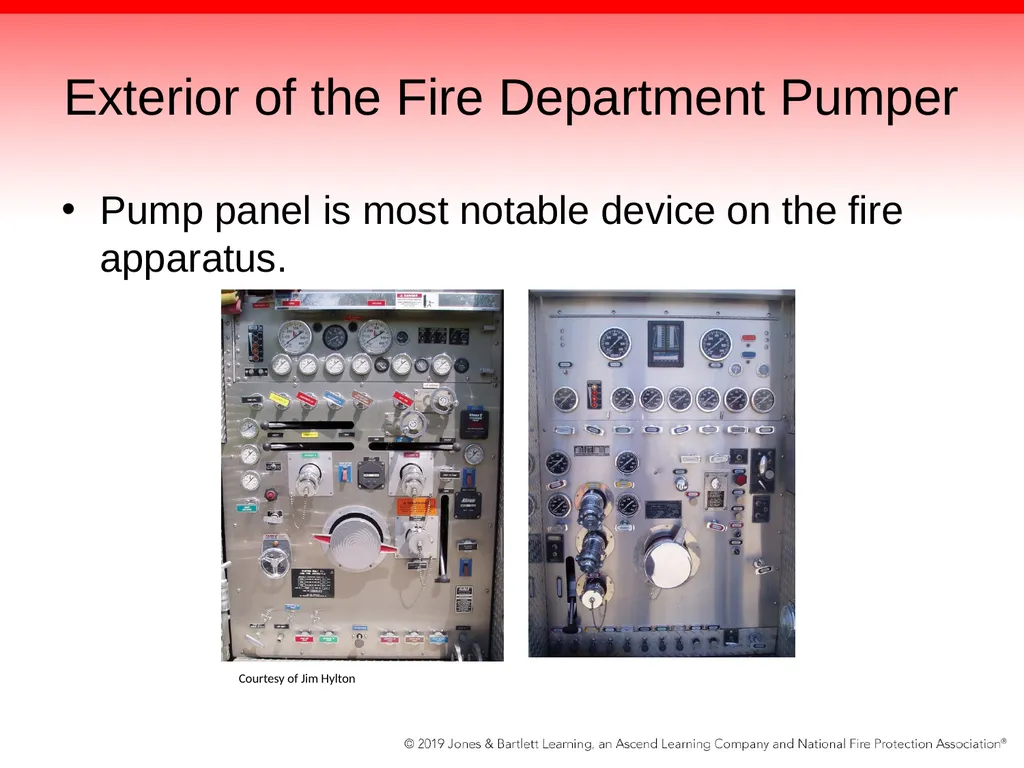
slide8. Exterior of the Fire Department Pumper Pump panel is most notable device on the fire apparatus. Courtesy of Jim Hylton<br>
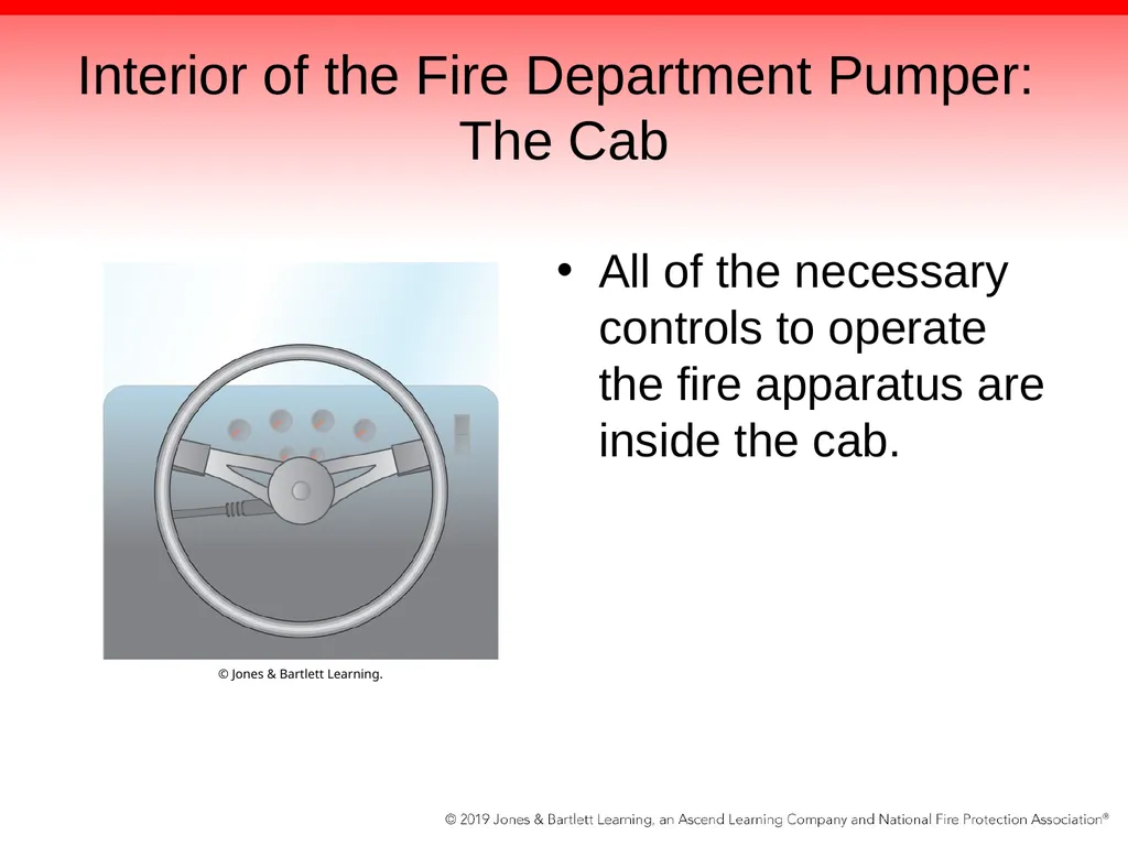
slide9. Interior of the Fire Department Pumper: The Cab All of the necessary controls to operate the fire apparatus are inside the cab. © Jones & Bartlett Learning.<br>
slide10. Interior of the Fire Department Pumper: The Cab Many of the controls/features are similar to those found in other large vehicles, but some are very different.
Controls to engage fire pump or operate emergency lights
The fire apparatus should not be operated like other vehicles.<br>
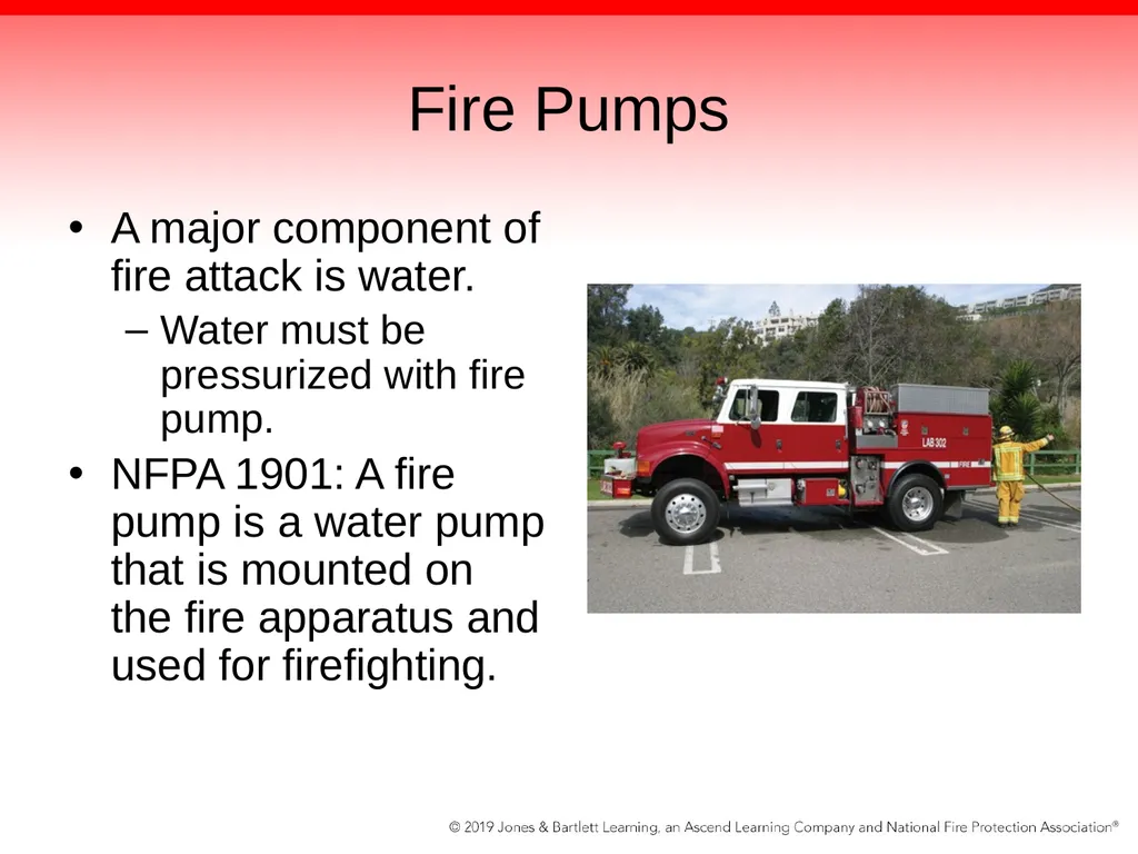
slide11. Fire Pumps A major component of fire attack is water.
Water must be pressurized with fire pump.
NFPA 1901: A fire pump is a water pump that is mounted on the fire apparatus and used for firefighting.<br>
slide12. Fire Pumps Fire apparatus designed for responding to small vegetation fires have relatively small capacities.
Do not carry large amounts of water
Devices usually mounted on fire apparatus
Have a separate engine to power them<br>
slide13. Fire Pumps Some pumps are operated in a stationary position.
Tend to be much larger
Have a greater capacity
Used to combat fires in structures such as homes and commercial buildings
Powered through the transmission in the fire apparatus’ engine
Other pumps may be equipped with pump-and roll capabilities.<br>
slide14. Fire Pumps No matter the size of the fire pump, it must meet certain requirements.
NFPA 1901: if a pumping system is rated at 3000 gpm, it must deliver water at the following rates:
100% of rate capacity at 150 psi net pump pressure
70% of rated capacity at 200 psi net pressure
50% of rated capacity at 250 psi net pressure<br>
slide15. Fire Pumps The maximum amount of water the fire pump can deliver is at 150 psi (1000 kPa) net pump pressure.
As the psi rate increases, the amount of water that can be delivered decreases.
After the fire pump reaches capacity, increasing the rpm only increases the pressure.
Avoid cavitation when this happens.<br>
slide16. Fire Pumps A fire pump rated at less than 1500 gpm is capable of taking suction through 20 ft of suction hose and can discharge water in less than 30 seconds.
A fire pump rated at greater than 1500 gpm can discharge water in less than 45 seconds.
Larger fire pumps are allowed more time to operate from a draft because they have more space inside that must be exhausted of air before water can enter the pump.<br>
slide17. Fire Pumps The size and number of suction lines required vary according to the size of the fire pump.
All fire pumps are rated from a draft.
No added water pressure from an external source is used to offset the capacity of the fire pump.
Pump test is usually conducted at the manufacturer by a third party.
Underwriters Laboratories (UL) certification<br>
slide18. Fire Pumps When you engage the pump, you need a mechanism to ensure it is running.
Indicator light in the driving compartment is illuminated when fire pump is pumping.
“Throttle Ready” indicator at pump panel signals when all necessary steps have been taken to ensure proper safe pumping.
Pressure is indicated on the master discharge gauge of pump panel.<br>
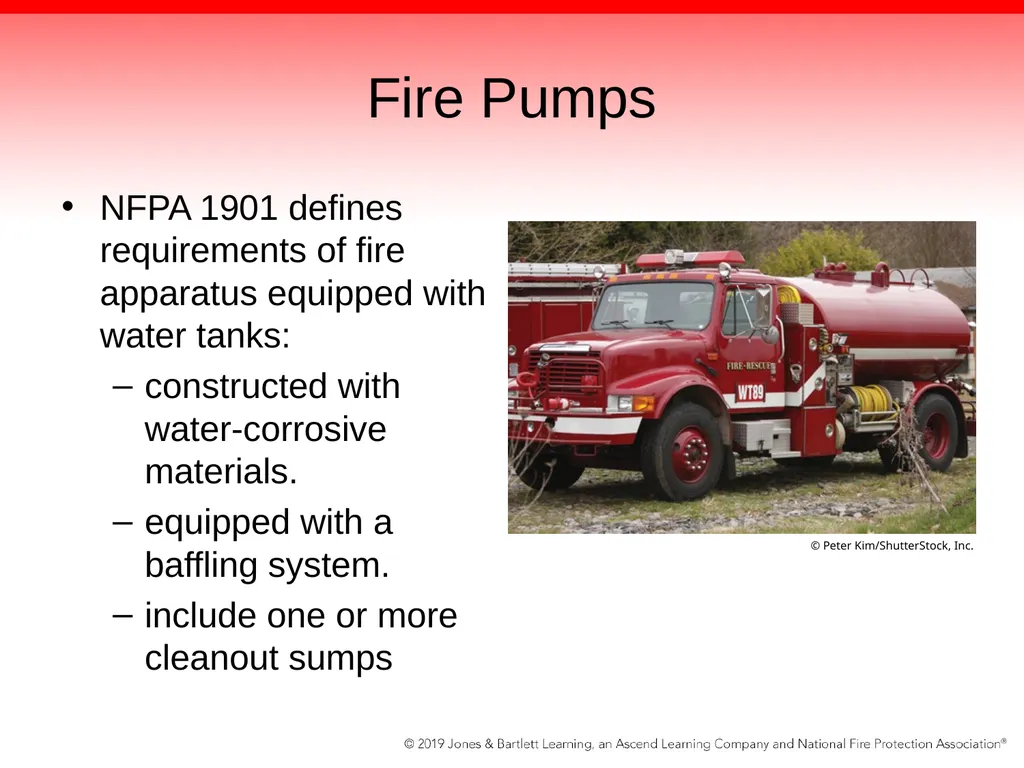
slide19. Fire Pumps NFPA 1901 defines requirements of fire apparatus equipped with water tanks:
constructed with water-corrosive materials.
equipped with a baffling system.
include one or more cleanout sumps © Peter Kim/ShutterStock, Inc.<br>
slide20. Fire Pumps NFPA 1901 covers many other aspects of water tanks.
Water-level indicators
Tank-to-pump intakes
Filling
Venting
External filling issues<br>
slide21. Fire Pumps Fires are extinguished when the proper amount of water is applied.
A pump is a mechanical device used to move fluids.
Pumps displace the fluid, which causes fluid to move or flow.
Resistance to flow creates pressure.
Higher pressures = less volume or flow
Higher flows = less pressure
Pumps cannot provide high pressure and high flow at the same time.<br>
slide22. Positive-Displacement Pump Produces a flow by capturing a specific volume of fluid per pump revolution and reducing the fluid void by a mechanical means
Displaces the liquid by creating a space between the pumping elements and trapping the liquid in the space
As pumping element moves, it reduces the size of this space, which in turn forces the fluid out of the pump<br>
slide23. Positive-Displacement Pump Relies on tightly fitting parts to function properly
Self-priming
Can move air or water during every revolution because the parts fit together so closely
Ideal for use as a priming pump for centrifugal pumps
Connected to the top of the centrifugal pump
Draws air and water from the top of the pump until a constant flow of water is achieved<br>
slide24. Positive-Displacement Pump May also be used as high-pressure auxiliary pumps or portable pumps
Performance of these pumps will begin to deteriorate as they wear down over time and with excessive use.
Presence of sand and other debris can cause the moving parts to wear out prematurely.<br>
slide25. Positive-Displacement Pump Two broad classifications of positive displacement pumps:
Rotary pumps
Exhibit a circular motion
Piston pumps
Have an up-and-down action<br>
slide26. Piston Pumps A piston moves back and forth inside the unit to move the liquid out of a cylinder.
As piston moves, water is drawn in from the intake side of the pump and expelled out the discharge side of the pump.
As piston moves faster, liquid will be discharged faster.<br>
slide27. Piston Pumps Three moving parts: piston, intake valve, discharge valve
Piston creates a seal in the cylinder to separate the intake side and the discharge side.
Intake and discharge valves create or block their respective openings to direct the water toward the target.
Two types of piston pumps available:
Single-acting and double-acting<br>
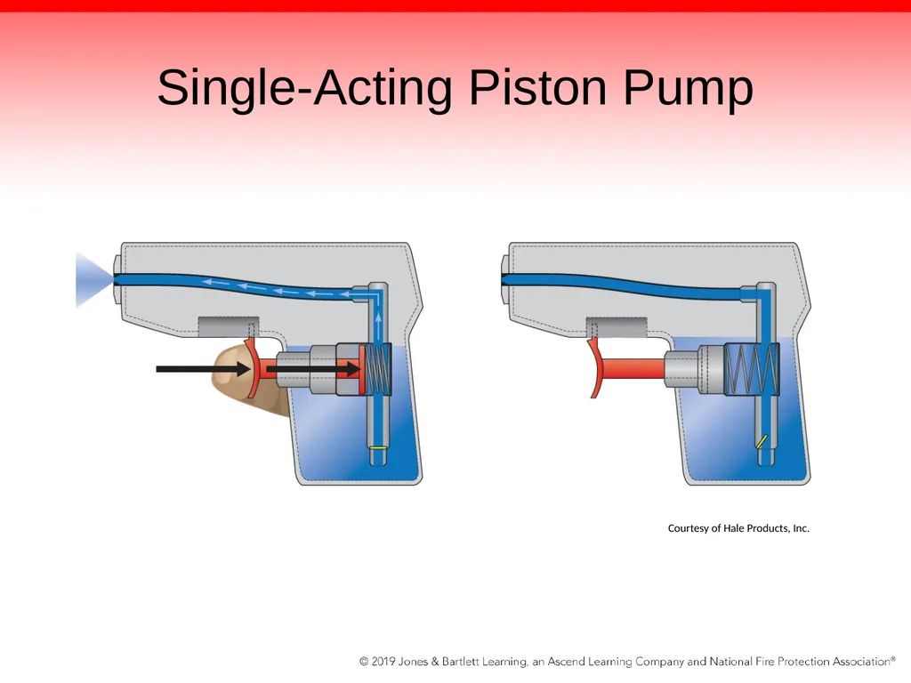
slide28. Single-Acting Piston Pump Has one intake side and one discharge side, both of which are located at the same ends of the cylinder
As the piston moves upward, away from the intake side, a vacuum is created in the cylinder.
Vacuum causes the intake valve to open and fill the cylinder with water.<br>
slide29. Single-Acting Piston Pump At the discharge side of the pump, the discharge valve remains in the closed position.
Once the piston moves in the opposite direction, the intake valve closes and the discharge valve opens to expel the water.
Action is similar to a squirt gun.<br>
slide30. Single-Acting Piston Pump Courtesy of Hale Products, Inc.<br>
slide31. Double-Acting Piston Pump Allows water to flow more continuously than a single-acting piston pump while using only one piston
Still has periods of limited flow
Has both valves at each end
Cylinder fills with water on both the up and down strokes of the piston.<br>
slide32. Double-Acting Piston Pump When the piston is pulled upward, the water flows into the cylinder through the intake valve.
At the same time, water flows through the discharge valve on the other side of the piston.<br>
slide33. Rotary Pumps Typically used as the priming pump for a centrifugal pump
Operate in a circular motion and discharge a constant flow of water with each revolution
Pumping element rotates, expanding the volume inside to allow water to enter
Area in which fluid is contained is reduced.
Water is forced out of the pump.
Result is a smooth, continuous flow of water.<br>
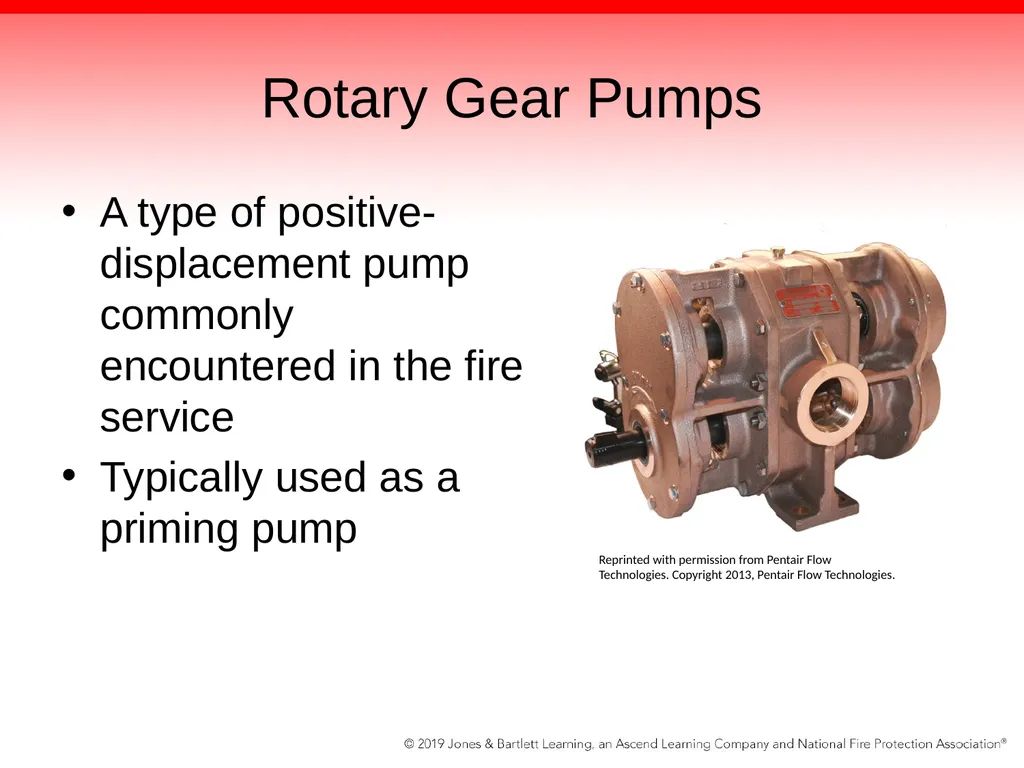
slide34. Rotary Gear Pumps A type of positive-displacement pump commonly encountered in the fire service
Typically used as a priming pump Reprinted with permission from Pentair Flow Technologies. Copyright 2013, Pentair Flow Technologies.<br>
slide35. Rotary Gear Pumps Use two gears driven by a 12-volt electric motor
Inside the pump casing, two gears rotate in opposite directions.
Gears are positioned closely to each other and to the inside of the pump casing, forming a watertight seal.
As the two gears mesh together, they trap water and move it to the discharge side.<br>
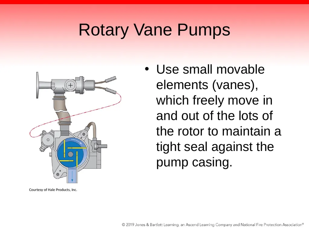
slide36. Rotary Vane Pumps Use small movable elements (vanes), which freely move in and out of the lots of the rotor to maintain a tight seal against the pump casing. Courtesy of Hale Products, Inc.<br>
slide37. Rotary Vane Pumps Vanes are positioned off-center inside the pump casing
Automatically maneuver in and out to compensate for changes in the pump casing
As vanes approach the intake side of the pump, the void space increases and the vanes slide farther out of their slots.
Water then flows in between these vanes, becoming trapped there.<br>
slide38. Rotary Vane Pumps When the vanes approach the discharge side of the pump, the void space decreases and the vanes slide farther back into their slots.
Water trapped in between the vanes is then discharged from the pump
Centrifugal force keeps the vane tightly pressed against the pump casing, ensuring a tight seal.
Makes the pump operate very efficiently<br>
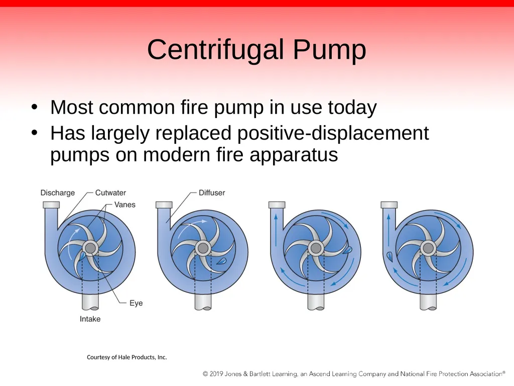
slide39. Centrifugal Pump Most common fire pump in use today
Has largely replaced positive-displacement pumps on modern fire apparatus Courtesy of Hale Products, Inc.<br>
slide40. Centrifugal Pump Does not flow a definite amount of water with each revolution; the flow or amount of water discharged is based on the pressures at the discharge side of the pump.
At higher discharge pressures, the pump will flow lower volumes but will create higher pressures.
As the pump spins more slowly, it will flow higher volumes of water at lower pressure on the discharge side.<br>
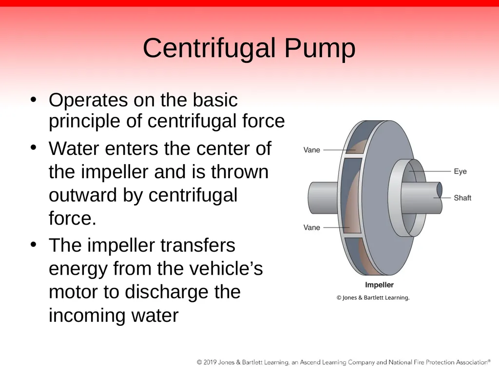
slide41. Centrifugal Pump Operates on the basic principle of centrifugal force
Water enters the center of the impeller and is thrown outward by centrifugal force.
The impeller transfers energy from the vehicle’s motor to discharge the incoming water © Jones & Bartlett Learning.<br>
slide42. Centrifugal Pump As the water leaves, a low-pressure area is created, causing more liquid to flow
Inside the impeller are vanes that divide the impeller
Liquid velocity if collected by the volute and converted to pressure
The piping is attached to the discharge header, where valves direct the flow to the intended hoselines<br>
slide43. Centrifugal Pump Can pump only water or other liquids
Devoid of any valves from the intake to the discharge side
Water is free to move between either side of the impeller when it is not spinning.
When the impeller is spinning, the water is taken from the intake side and flows out the discharge side.
Relies on the movement of water from the intake side to the discharge side to operate effectively<br>
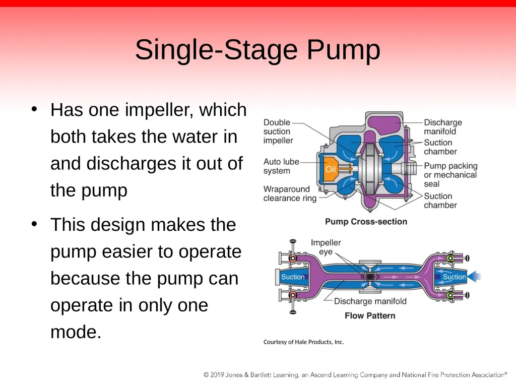
slide44. Single-Stage Pump Has one impeller, which both takes the water in and discharges it out of the pump
This design makes the pump easier to operate because the pump can operate in only one mode. Courtesy of Hale Products, Inc.<br>
slide45. Two-Stage Pump The most common type of multistage pump
Has two impellers enclosed in their own pump casings but part of a common housing
Impellers are identical and spin at the same speed.<br>
slide46. Two-Stage Pump At the discharge side of the first impeller, a transfer valve directs the water to either the pump’s discharge header or the intake side of the second impeller.
A transfer valve determines whether the pump will be operated in series/pressure mode or parallel/volume mode.
Both positions have their own strengths and weaknesses.<br>
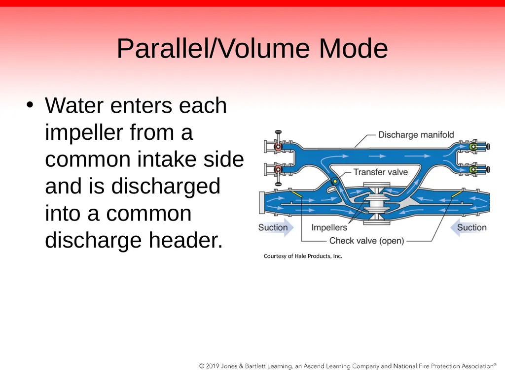
slide47. Parallel/Volume Mode Water enters each impeller from a common intake side and is discharged into a common discharge header. Courtesy of Hale Products, Inc.<br>
slide48. Parallel/Volume Mode Results in the pump’s maximum volume of water being discharged
In this mode, each of the two impellers pumps 50% of the pump’s total capacity.
When more than 50% of the pump’s rated capacity is needed on the fireground, the pump should be operated in this mode to ensure that the desired flow can be achieved.<br>
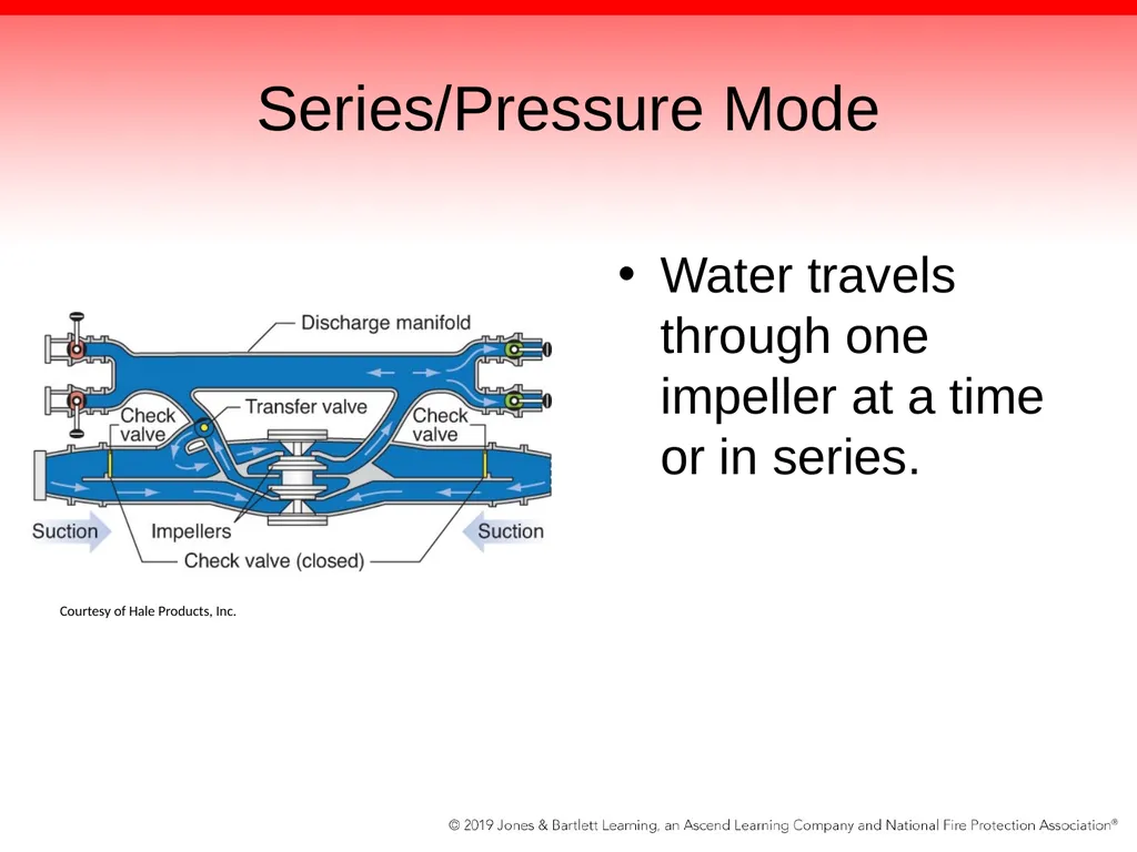
slide49. Series/Pressure Mode Water travels through one impeller at a time or in series. Courtesy of Hale Products, Inc.<br>
slide50. Series/Pressure Mode Water enters first-stage pump impeller’s intake side, gains pressure, and is discharged to the second-stage impeller’s intake side.
Second impeller then pumps the water out of the discharge header
This is the position in which two-stage pumps are most commonly operated.
Most fire responses do not require the pump to deliver more than 50% of the rated capacity.<br>
slide51. Fire Pumps A fire pump is rated by and tested to UL specifications.
100% of its rated capability at 150 psi for 20 minutes
70% of its rated capability at 200 psi for 10 minutes
50% of its rated capability at 250 psi for 10 minutes<br>
slide52. Fire Pumps Can be configured to provide pressures significantly greater than 250 psi
Directing the water from first impeller directly to second impeller and then to discharge
Control valve on pump panel indicates if impellers are in parallel/volume mode or series/pressure mode.
If pump operation requires a large volume of water, then pump should be operated in parallel/volume mode.<br>
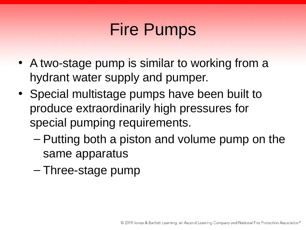
slide53. Fire Pumps A two-stage pump is similar to working from a hydrant water supply and pumper.
Special multistage pumps have been built to produce extraordinarily high pressures for special pumping requirements.
Putting both a piston and volume pump on the same apparatus
Three-stage pump<br>
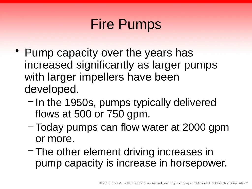
slide54. Fire Pumps Pump capacity over the years has increased significantly as larger pumps with larger impellers have been developed.
In the 1950s, pumps typically delivered flows at 500 or 750 gpm.
Today pumps can flow water at 2000 gpm or more.
The other element driving increases in pump capacity is increase in horsepower.<br>
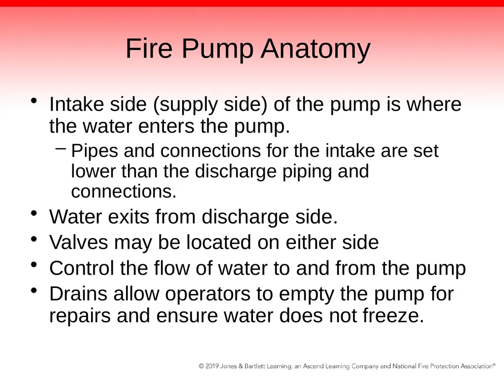
slide55. Fire Pump Anatomy Intake side (supply side) of the pump is where the water enters the pump.
Pipes and connections for the intake are set lower than the discharge piping and connections.
Water exits from discharge side.
Valves may be located on either side
Control the flow of water to and from the pump
Drains allow operators to empty the pump for repairs and ensure water does not freeze.<br>
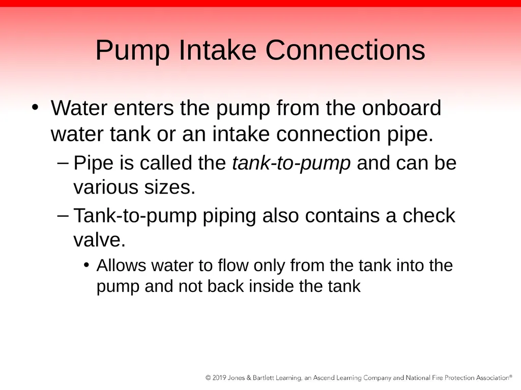
slide56. Pump Intake Connections Water enters the pump from the onboard water tank or an intake connection pipe.
Pipe is called the tank-to-pump and can be various sizes.
Tank-to-pump piping also contains a check valve.
Allows water to flow only from the tank into the pump and not back inside the tank<br>
slide57. Pump Intake Connections When the internal water tank is not used to supply the fire pump, an external water supply is needed
Enters the pump directly through the intake side via an intake connection pipe
Should have a sufficient number and size of intake connections to perform the pump certification test
National Standard Thread (NST) or sexless type connections (Storz connector)<br>
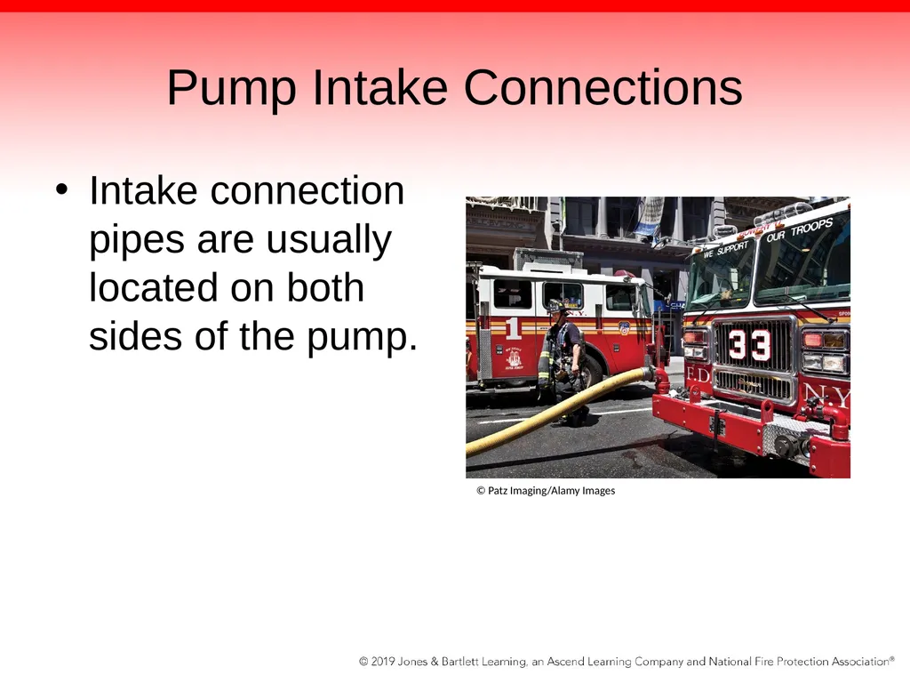
slide58. Pump Intake Connections Intake connection pipes are usually located on both sides of the pump. © Patz Imaging/Alamy Images<br>
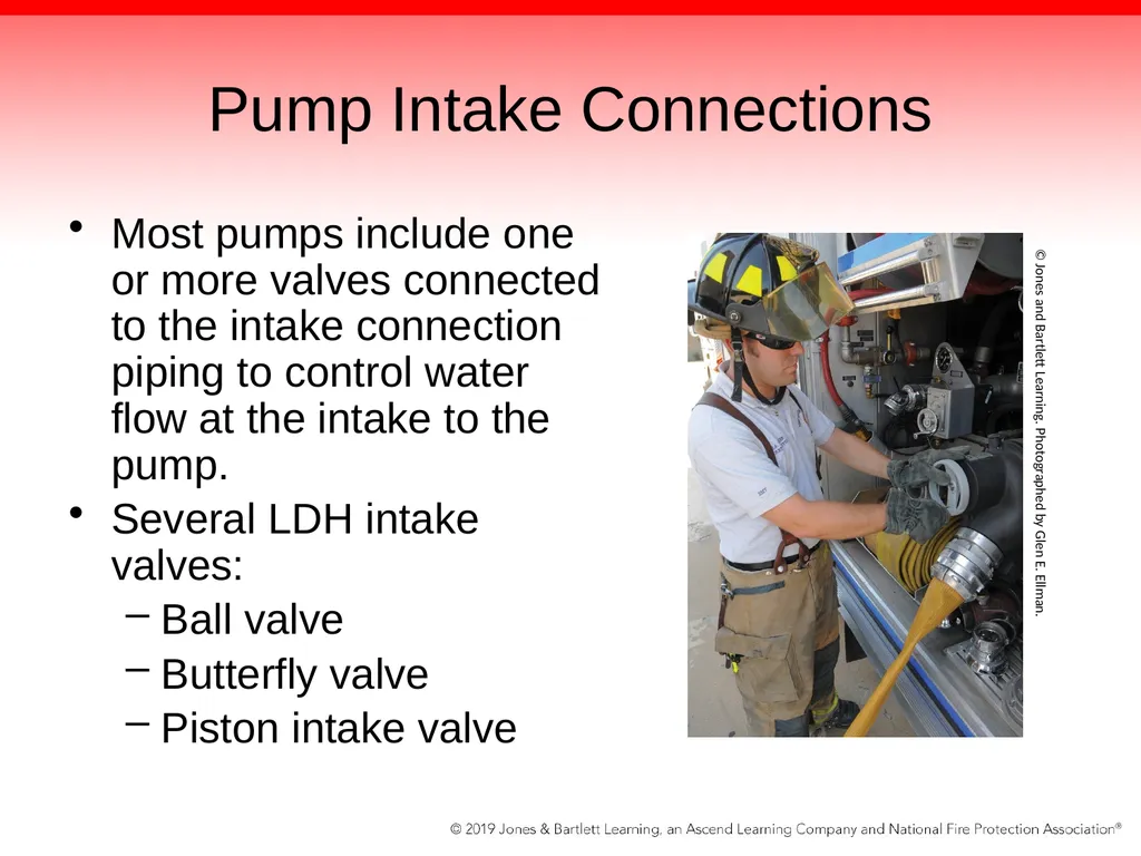
slide59. Pump Intake Connections Most pumps include one or more valves connected to the intake connection piping to control water flow at the intake to the pump.
Several LDH intake valves:
Ball valve
Butterfly valve
Piston intake valve © Jones and Bartlett Learning. Photographed by Glen E. Ellman.<br>
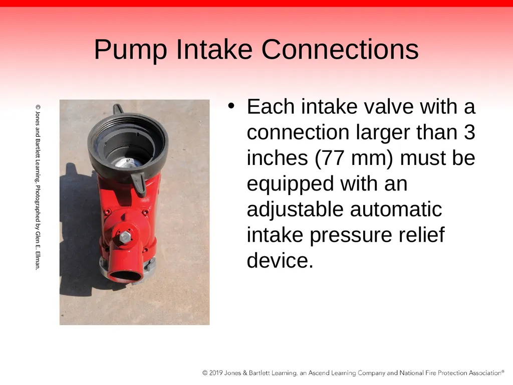
slide60. Pump Intake Connections Each intake valve with a connection larger than 3 inches (77 mm) must be equipped with an adjustable automatic intake pressure relief device. © Jones and Bartlett Learning. Photographed by Glen E. Ellman.<br>
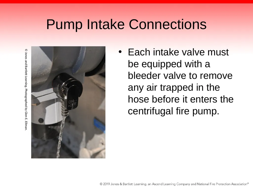
slide61. Pump Intake Connections Each intake valve must be equipped with a bleeder valve to remove any air trapped in the hose before it enters the centrifugal fire pump. © Jones and Bartlett Learning. Photographed by Glen E. Ellman.<br>
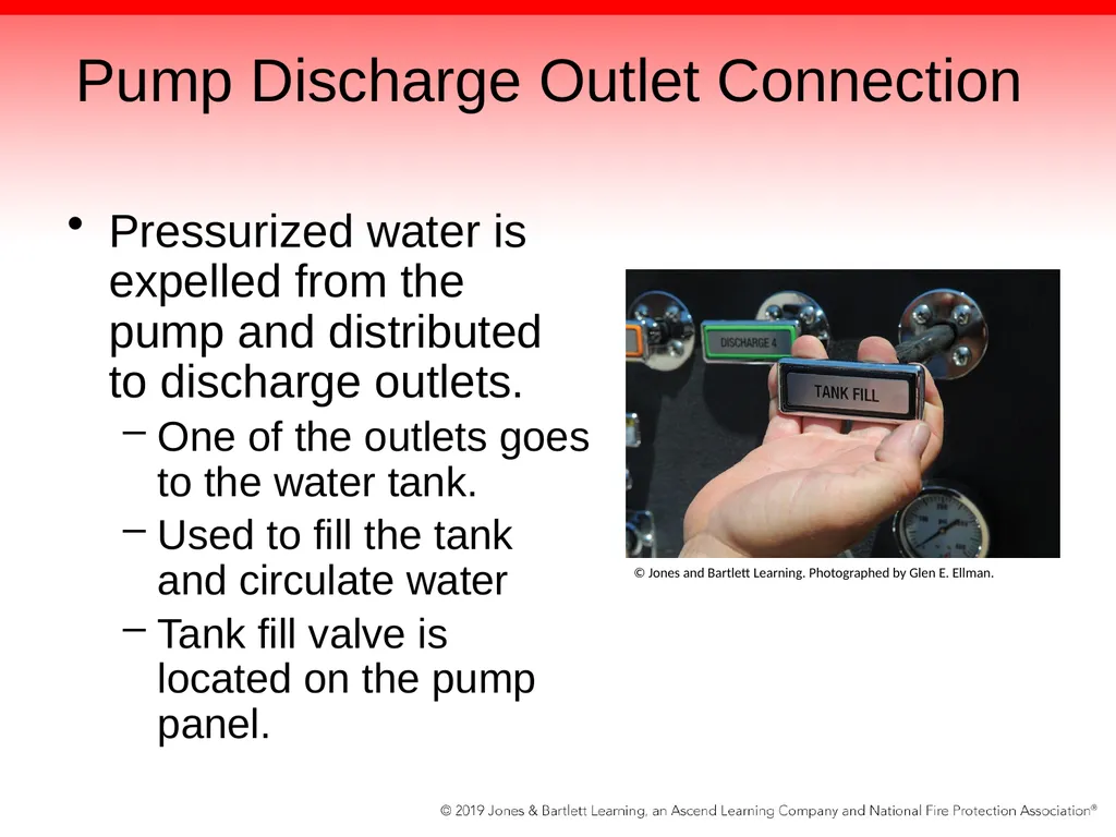
slide62. Pump Discharge Outlet Connection Pressurized water is expelled from the pump and distributed to discharge outlets.
One of the outlets goes to the water tank.
Used to fill the tank and circulate water
Tank fill valve is located on the pump panel. © Jones and Bartlett Learning. Photographed by Glen E. Ellman.<br>
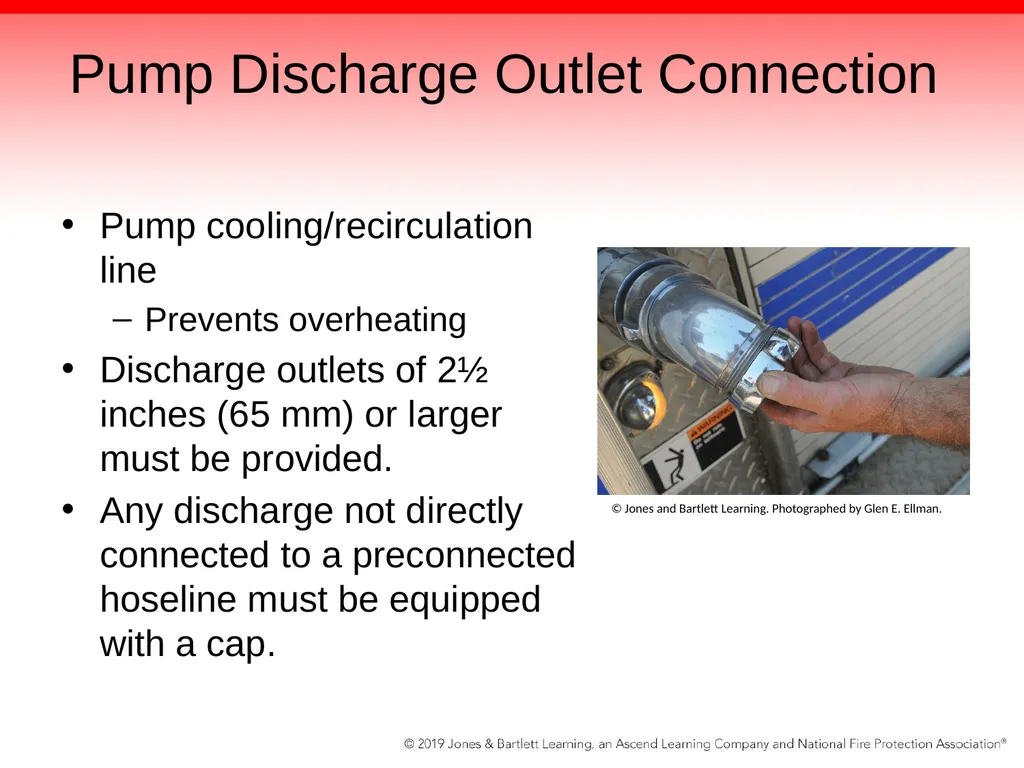
slide63. Pump Discharge Outlet Connection Pump cooling/recirculation line
Prevents overheating
Discharge outlets of 2½ inches (65 mm) or larger must be provided.
Any discharge not directly connected to a preconnected hoseline must be equipped with a cap. © Jones and Bartlett Learning. Photographed by Glen E. Ellman.<br>
slide64. Pump Discharge Outlet Connection Each discharge outlet must be equipped with a valve that can be opened and closed smoothly while operating at 250 psi.
A valve that can be operated from the pump operator’s position
An indicator to show when the valve is open or closed
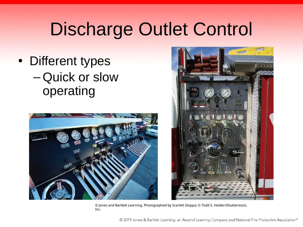
Different types of controls
Quick operating or slow operating<br>
slide65. Discharge Outlet Control Different types
Quick or slow operating © Jones and Bartlett Learning. Photographed by Scarlett Stoppa; © Todd S. Holder/Shutterstock, Inc.<br>
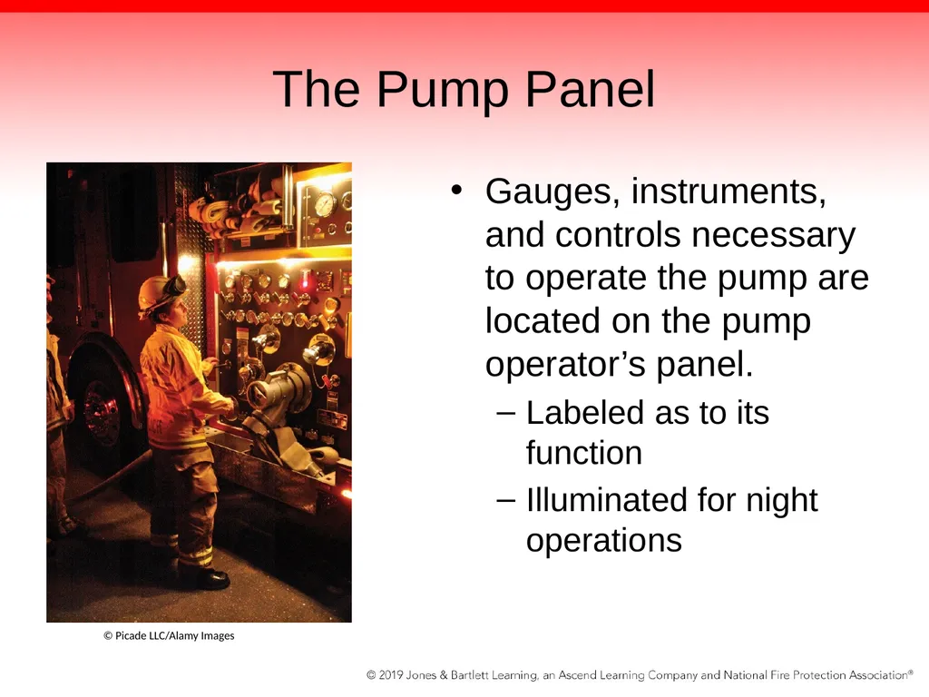
slide66. The Pump Panel Gauges, instruments, and controls necessary to operate the pump are located on the pump operator’s panel.
Labeled as to its function
Illuminated for night operations © Picade LLC/Alamy Images<br>
slide67. NPFA 1901 Pump Panel Requirements Master pump intake pressure gauge
Master pump discharge gauge
Pumping engine tachometer
Pumping engine coolant temperature gauge
Pumping engine oil pressure gauge
Voltmeter Pump pressure controls
Pumping engine throttle
Primer control
Water tank-to-pump valve control
Water tank fill valve control
Water tank level gauge
Fuel level indicator
Pump overheat indicator<br>
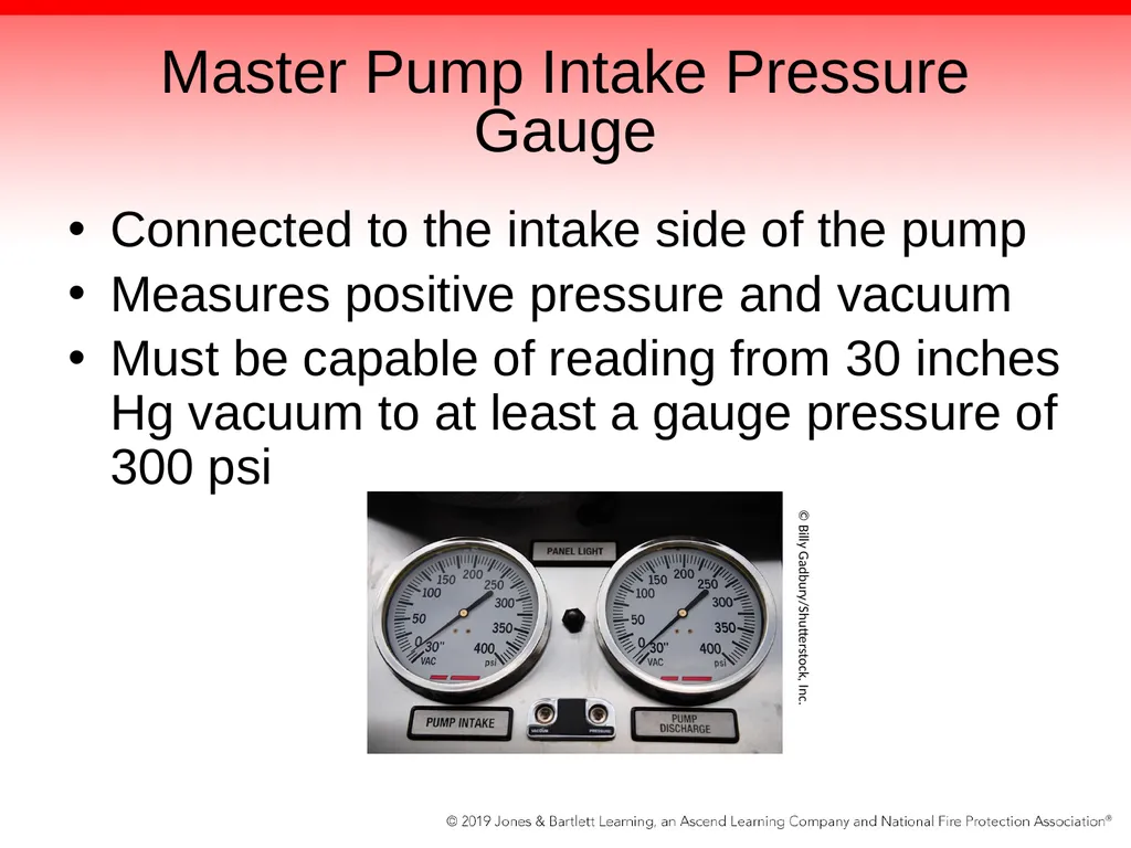
slide68. Master Pump Intake Pressure Gauge Connected to the intake side of the pump
Measures positive pressure and vacuum
Must be capable of reading from 30 inches Hg vacuum to at least a gauge pressure of 300 psi © Billy Gadbury/Shutterstock, Inc.<br>
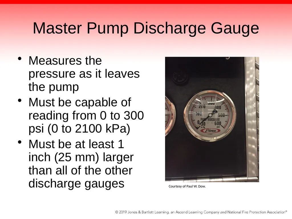
slide69. Master Pump Discharge Gauge Measures the pressure as it leaves the pump
Must be capable of reading from 0 to 300 psi (0 to 2100 kPa)
Must be at least 1 inch (25 mm) larger than all of the other discharge gauges Courtesy of Paul W. Dow.<br>
slide70. Pressure Gauge Must be provided for each discharge outlet that is 1½ inches (38 mm) or larger in size
Connected to the outlet of discharge valve
Two types of gauges:
Analog
Digital<br>
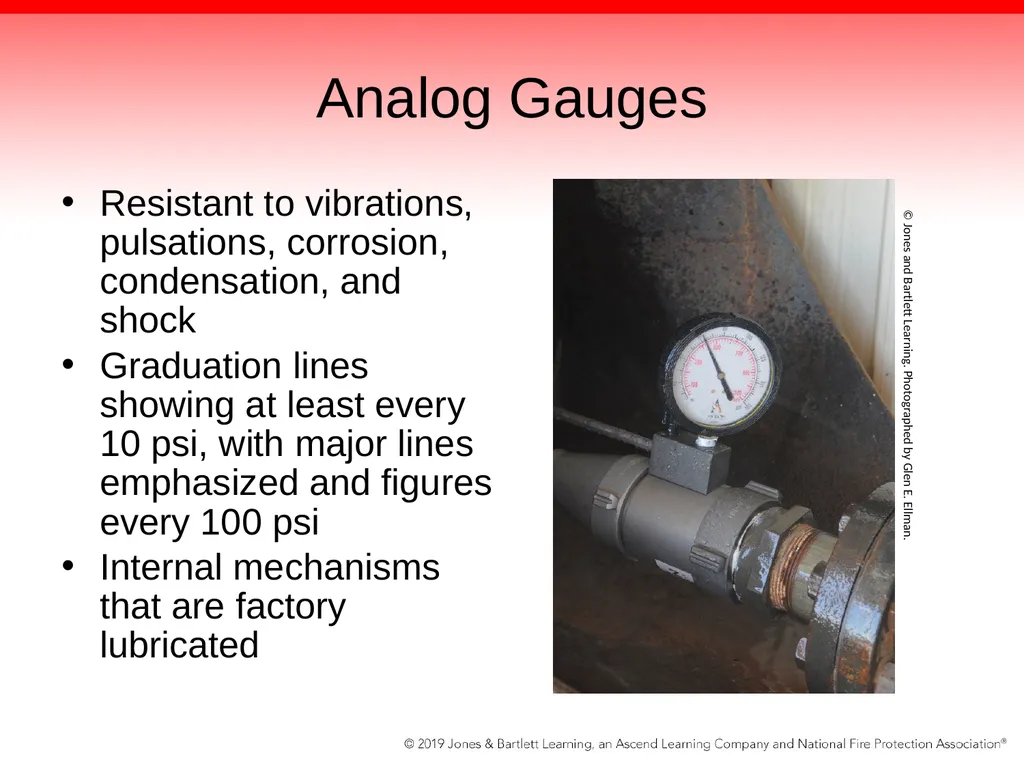
slide71. Analog Gauges Resistant to vibrations, pulsations, corrosion, condensation, and shock
Graduation lines showing at least every 10 psi, with major lines emphasized and figures every 100 psi
Internal mechanisms that are factory lubricated © Jones and Bartlett Learning. Photographed by Glen E. Ellman.<br>
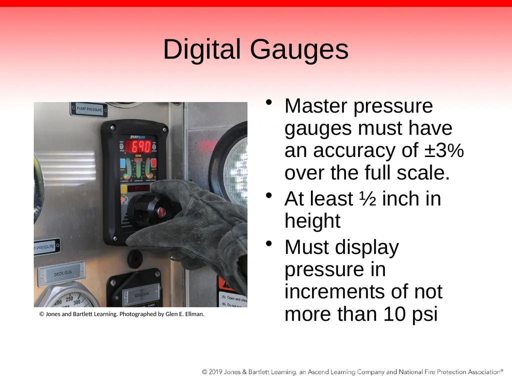
slide72. Digital Gauges Master pressure gauges must have an accuracy of ±3% over the full scale.
At least ½ inch in height
Must display pressure in increments of not more than 10 psi © Jones and Bartlett Learning. Photographed by Glen E. Ellman.<br>
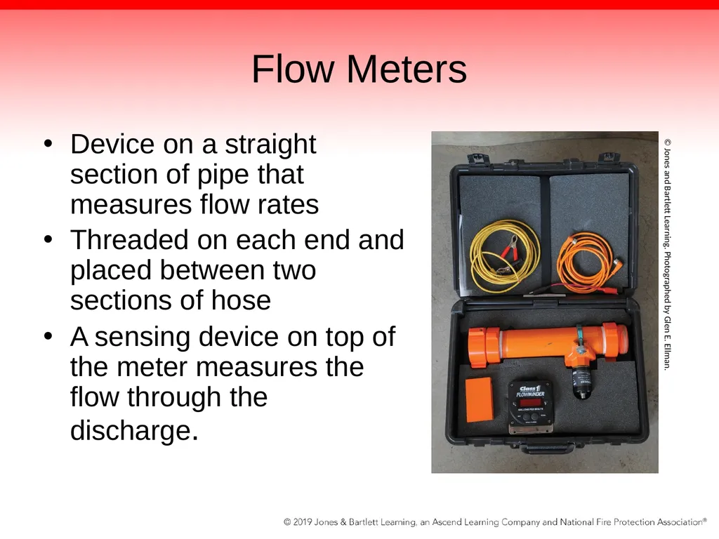
slide73. Flow Meters Device on a straight section of pipe that measures flow rates
Threaded on each end and placed between two sections of hose
A sensing device on top of the meter measures the flow through the discharge. © Jones and Bartlett Learning. Photographed by Glen E. Ellman.<br>
slide74. Flow Meters Flow meters give an indication of the actual volume of water being discharged through each line.
Many types of flow meters are available; must have a pressure gauge
Generally accurate within 1% to 3%
Reports the discharge port flow without the operator having to calculate<br>
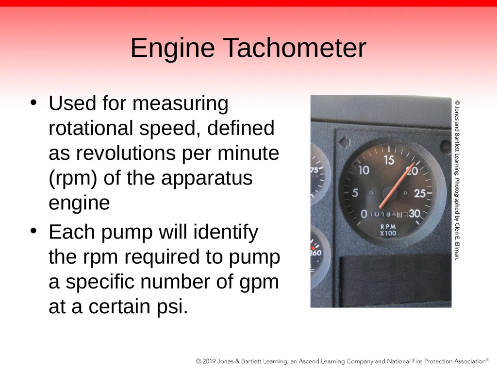
slide75. Engine Tachometer Used for measuring rotational speed, defined as revolutions per minute (rpm) of the apparatus engine
Each pump will identify the rpm required to pump a specific number of gpm at a certain psi. © Jones and Bartlett Learning. Photographed by Glen E. Ellman.<br>
slide76. Engine Coolant Temperature Gauge Indicates the temperature of the coolant inside the engine
High temps could cause severe damage to the engine and shut it down
Low temps mean inefficient operating<br>
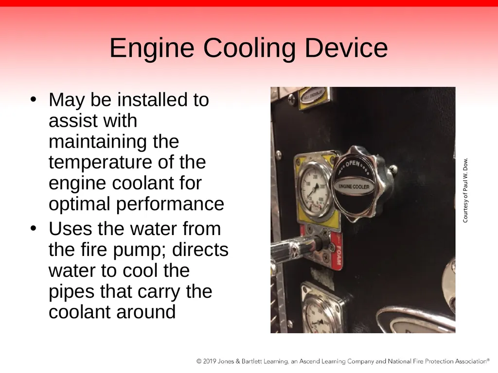
slide77. Engine Cooling Device May be installed to assist with maintaining the temperature of the engine coolant for optimal performance
Uses the water from the fire pump; directs water to cool the pipes that carry the coolant around Courtesy of Paul W. Dow.<br>
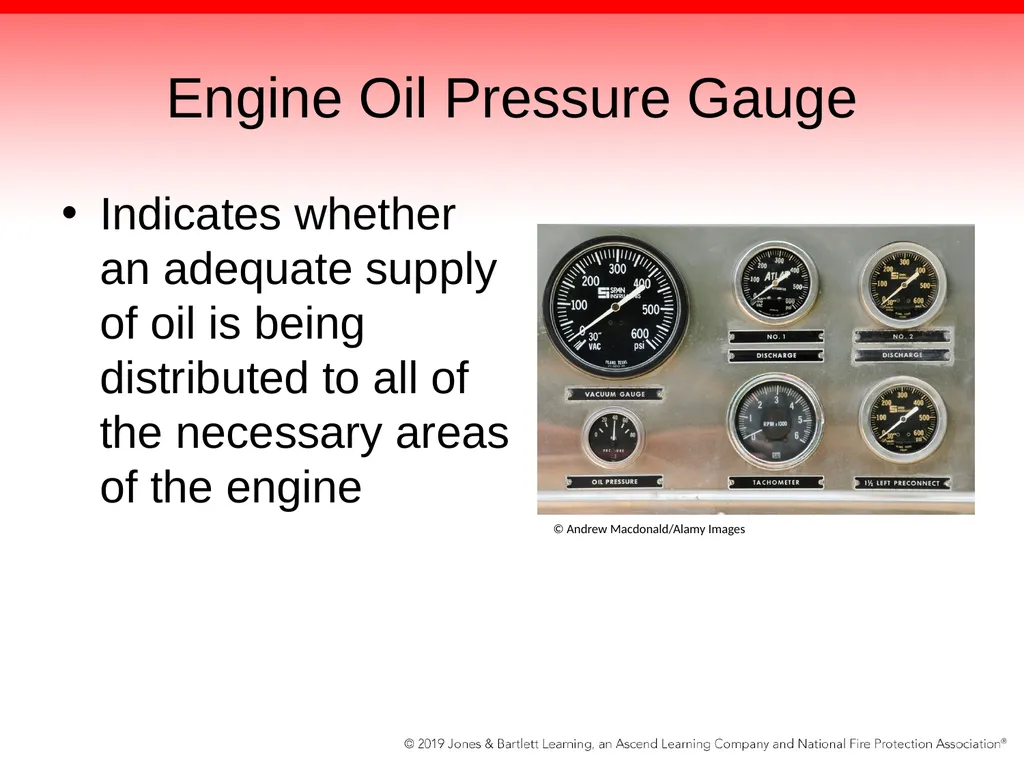
slide78. Engine Oil Pressure Gauge Indicates whether an adequate supply of oil is being distributed to all of the necessary areas of the engine © Andrew Macdonald/Alamy Images<br>
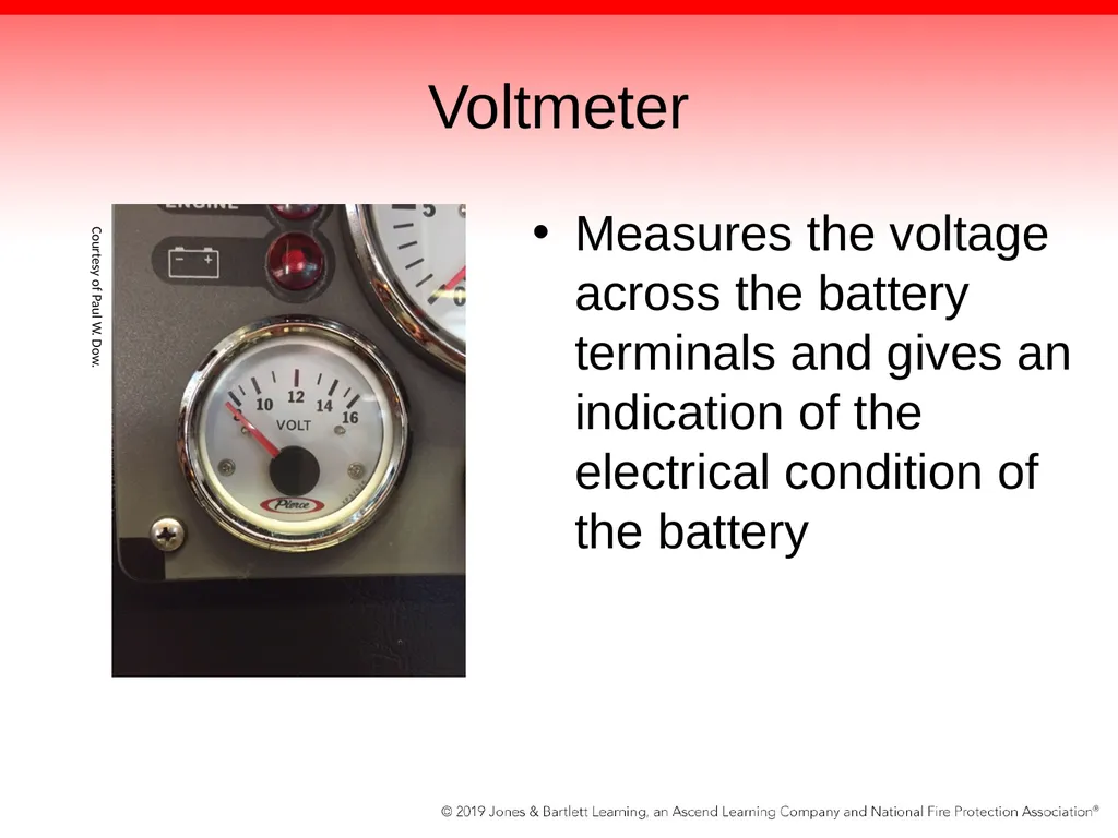
slide79. Voltmeter Measures the voltage across the battery terminals and gives an indication of the electrical condition of the battery Courtesy of Paul W. Dow.<br>
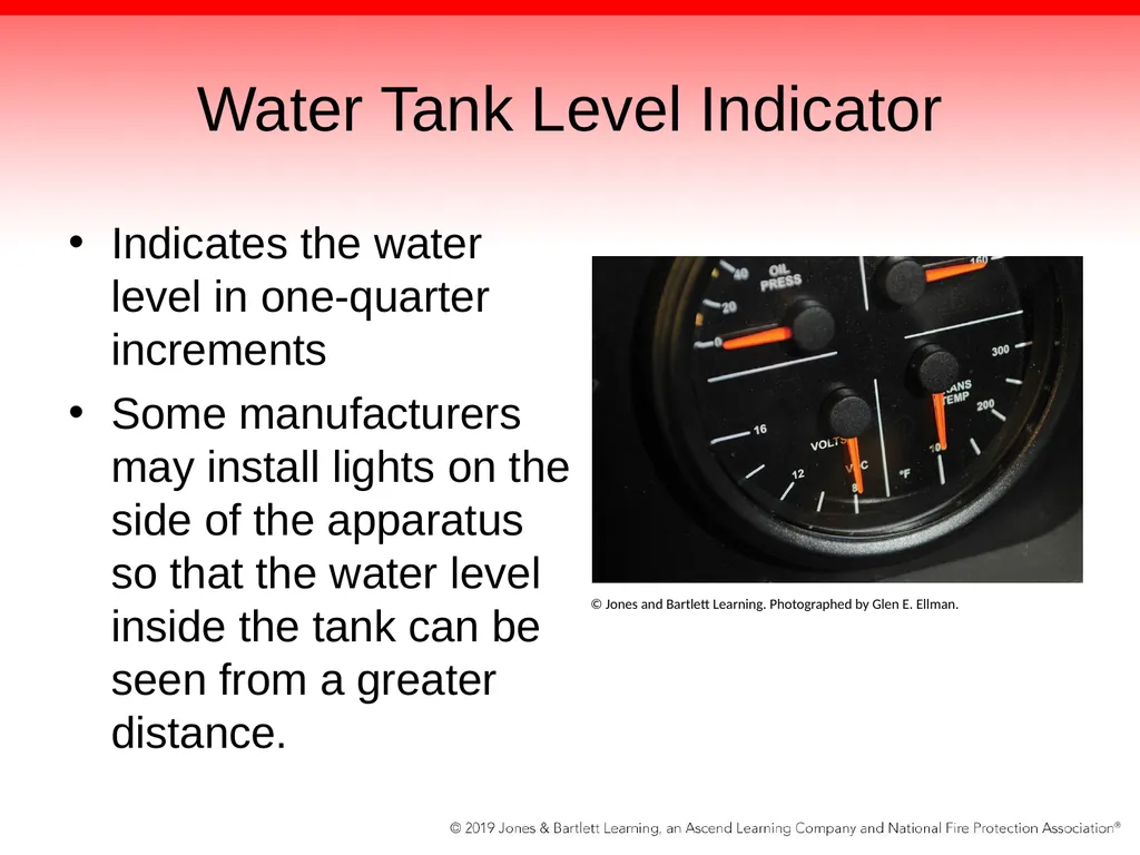
slide80. Water Tank Level Indicator Indicates the water level in one-quarter increments
Some manufacturers may install lights on the side of the apparatus so that the water level inside the tank can be seen from a greater distance. © Jones and Bartlett Learning. Photographed by Glen E. Ellman.<br>
slide81. The Pump Panel Fuel level indicator
Red warning light indicating when the fuel level falls below one-quarter of the capacity of the tank must be provided on the pump operator’s panel.
Primer control
Used to expel any air that may be trapped inside the pump and during drafting operations<br>
slide82. Pump Pressure Control Systems Control the discharge pressures and protect flow fighters who are operating hose streams
Protect the discharge hose from damage in the event attack hose streams are shut off or other valves are closed, reducing flow rates
Driver/operator can ensure that fire fighters on the nozzle do not receive excessive pressure as hoselines are opened and closed.
Two systems are used: discharge pressure relief valve and pressure governor<br>
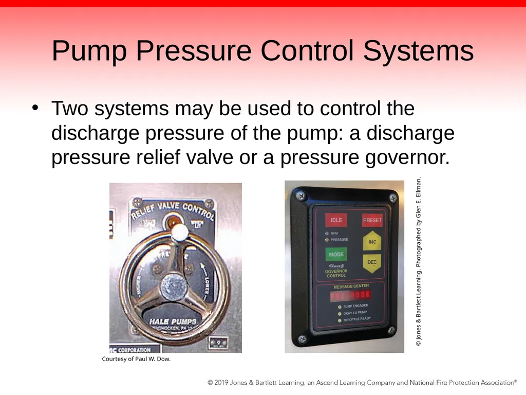
slide83. Pump Pressure Control Systems Two systems may be used to control the discharge pressure of the pump: a discharge pressure relief valve or a pressure governor. Courtesy of Paul W. Dow. © Jones & Bartlett Learning. Photographed by Glen E. Ellman.<br>
slide84. Pumping Engine Throttle Apparatus engine powers the fire pump.
The operator must have a way of increasing or decreasing the engine speed from the pump panel.
Pump panel must be equipped with a throttle control that holds its set position to control the engine speed.
May be manual throttle control or electronic<br>
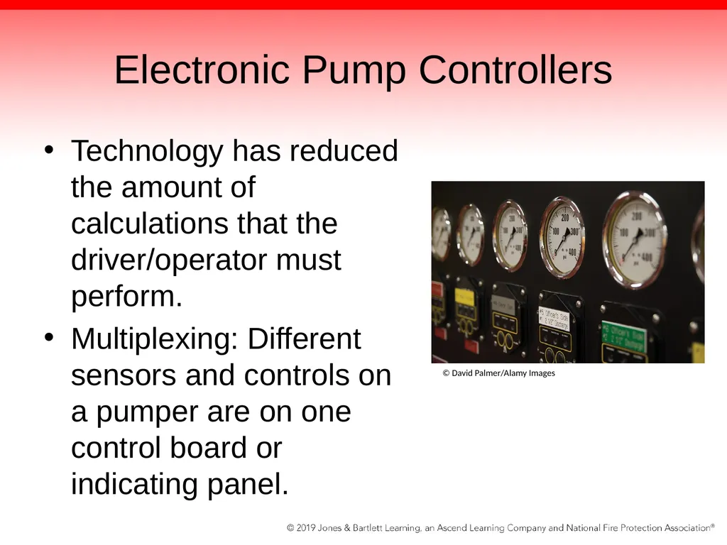
slide85. Electronic Pump Controllers Technology has reduced the amount of calculations that the driver/operator must perform.
Multiplexing: Different sensors and controls on a pumper are on one control board or indicating panel. © David Palmer/Alamy Images<br>
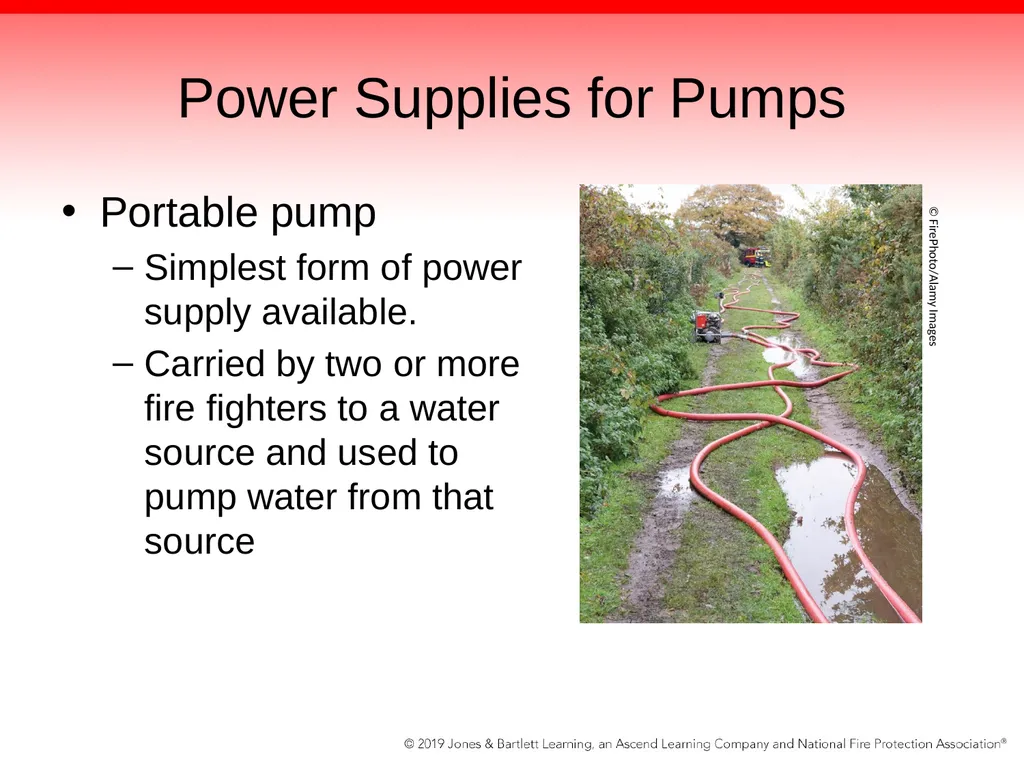
slide86. Power Supplies for Pumps Portable pump
Simplest form of power supply available.
Carried by two or more fire fighters to a water source and used to pump water from that source © FirePhoto/Alamy Images<br>
slide87. Power Supplies for Pumps Portable pump (cont’d)
Has a small engine attached directly to the pump and provides power on a one-to-one basis
Typically no gear box, clutch, shifting level, or other devices to operate
Has a pump-and-roll capability
That is, the ability to discharge water as the apparatus is moving<br>
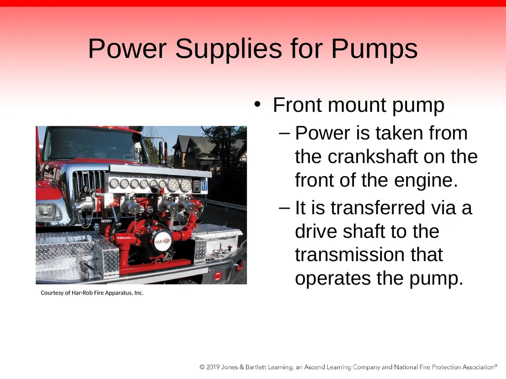
slide88. Power Supplies for Pumps Front mount pump
Power is taken from the crankshaft on the front of the engine.
It is transferred via a drive shaft to the transmission that operates the pump. Courtesy of Har-Rob Fire Apparatus, Inc.<br>
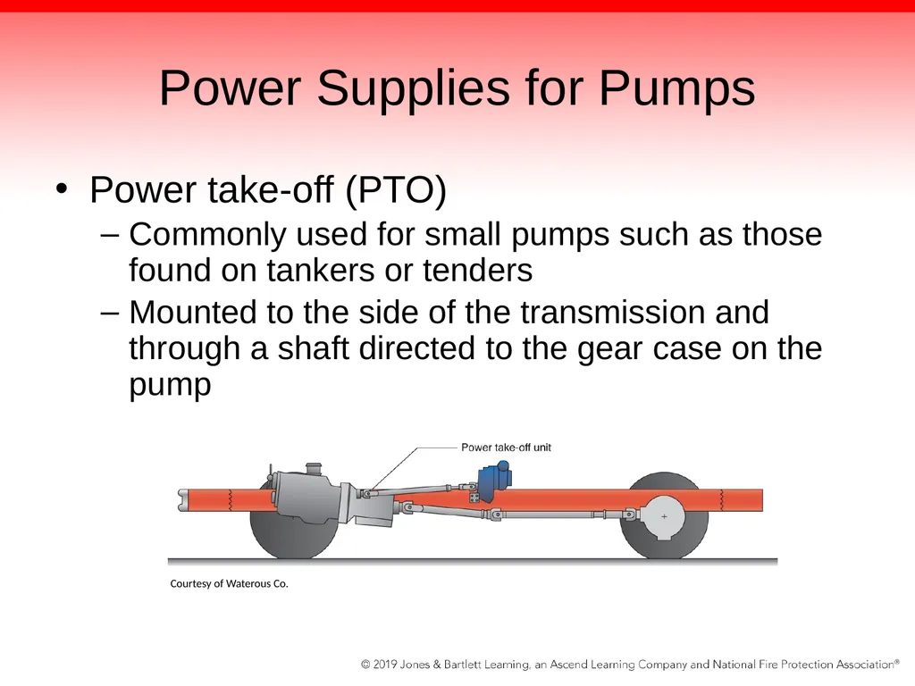
slide89. Power Supplies for Pumps Power take-off (PTO)
Commonly used for small pumps such as those found on tankers or tenders
Mounted to the side of the transmission and through a shaft directed to the gear case on the pump Courtesy of Waterous Co.<br>
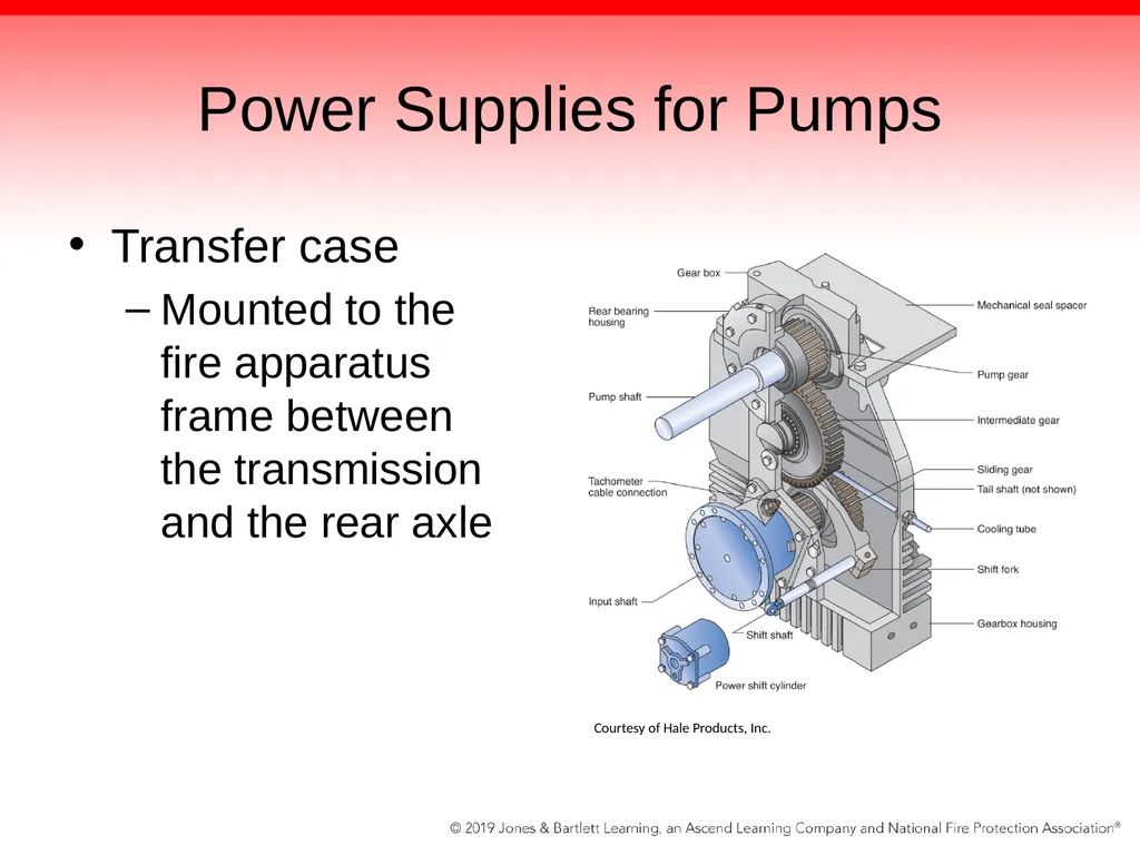
slide90. Power Supplies for Pumps Transfer case
Mounted to the fire apparatus frame between the transmission and the rear axle Courtesy of Hale Products, Inc.<br>
slide91. Power Supplies for Pumps Transfer case (cont’d)
Drive shaft connects the fire apparatus’ transmission to the transfer case.
When you place the pump into pump gear in the cab, you are transferring the power from the rear axle to the pump.
Gear ratio is typically 1:1<br>
slide92. Power Supplies for Pumps The speed of the pump is directly related to the speed of the transmission.
First gear turns the pump more slowly.
Fifth gear turns the pump more quickly.
Automatic transmissions are specifically made for pumping operations that will lock into the gear intended for pump operations once the fire apparatus is placed in pumping mode.<br>
slide93. Summary As the driver/operator of the pump apparatus, you must understand how pumps operate so that you are able to fix any problems that you may encounter on the fireground.
The pump panel is the most notable device on the fire apparatus. Once you have a thorough understanding of the pump behind it and the way in which the pump functions, you will be capable of confidently operating the fire pump.
It is important for the new driver/operator to understand that the fire apparatus is not like any other vehicle—and, therefore, should not be operated like other vehicles.<br>
slide94. Summary According to the NFPA, a pump is defined as a provider of liquid flow and pressure dedicated to fire protection. It is a mechanical device used to move fluids.
The goal in firefighting is for the pump to move water from a source, such as the onboard water tank, to the fire through the attack lines. To do so successfully, the driver/operator must understand how each different type of pump works.
The fire service primarily uses two types of pumps: positive-displacement pumps and centrifugal pumps. Each type relies on very different operating principles and offers a very different set of features.<br>
slide95. Summary Positive-placement pumps produce a flow by capturing a specific volume of fluid per pump revolution and reducing the fluid void by mechanical means to displace the pumping fluid.
Two broad classifications of positive-displacement pumps exist: the piston pump and the rotary pump.
Centrifugal pumps—the most common fire pumps in use today—do not flow a definite amount of water with each revolution; instead, the flow or amount of water discharged is based on the pressures at the discharge side of the pump.<br>
slide96. Summary The two main sides of all pumps are the intake and discharge sides.
Intake relief valves prevent excessive pressure from building up on the intake side of the pump.
Discharge relief valves prevent excessive pressure from building up on the discharge side of the pump.
The pump panel consists of several gauges, controls, and valves to operate the pump.<br>
slide2. Knowledge Objectives Explain the importance of understanding the fire pump and its systems.
Describe the exterior and interior features of a pumper.
Define the term pump.
Explain the basic operations of positive-displacement pumps and centrifugal pumps.
Explain the different types of positive-displacement pumps.<br>
slide3. Knowledge Objectives Explain the different types of centrifugal pumps.
Describe a single-stage pump and a two-stage pump.
Describe the intake side of the fire pump.
Describe the discharge sides of a pump.
Describe the pump valves and drains.
Describe the components of the pump panel.<br>
slide4. Introduction Pumps are vital to the operations of firefighting.
Fire fighters must be able to discharge water under pressure to extinguish fire. © Keith Muratori/ShutterStock, Inc.<br>
slide5. Introduction The driver/operator must understand how pumps operate in order to fix any problems they may encounter on the fireground.
“Don’t just be a knob puller—know what you are doing.”
Ensure that you have a thorough understanding of how each pump operates.<br>
slide6. Exterior of the Fire Department Pumper A large fire pump with hose and tools used to extinguish fires
Most common fire apparatus
Compartments hold various tools and equipment.
Ground ladders may be mounted on the side of the apparatus.<br>
slide7. Exterior of the Fire Department Pumper Supply hose and attack lines are stored in the hose bed.
Most pumpers carry preconnected attack lines.
Usually located above or on side of pump panel<br>
slide8. Exterior of the Fire Department Pumper Pump panel is most notable device on the fire apparatus. Courtesy of Jim Hylton<br>
slide9. Interior of the Fire Department Pumper: The Cab All of the necessary controls to operate the fire apparatus are inside the cab. © Jones & Bartlett Learning.<br>
slide10. Interior of the Fire Department Pumper: The Cab Many of the controls/features are similar to those found in other large vehicles, but some are very different.
Controls to engage fire pump or operate emergency lights
The fire apparatus should not be operated like other vehicles.<br>
slide11. Fire Pumps A major component of fire attack is water.
Water must be pressurized with fire pump.
NFPA 1901: A fire pump is a water pump that is mounted on the fire apparatus and used for firefighting.<br>
slide12. Fire Pumps Fire apparatus designed for responding to small vegetation fires have relatively small capacities.
Do not carry large amounts of water
Devices usually mounted on fire apparatus
Have a separate engine to power them<br>
slide13. Fire Pumps Some pumps are operated in a stationary position.
Tend to be much larger
Have a greater capacity
Used to combat fires in structures such as homes and commercial buildings
Powered through the transmission in the fire apparatus’ engine
Other pumps may be equipped with pump-and roll capabilities.<br>
slide14. Fire Pumps No matter the size of the fire pump, it must meet certain requirements.
NFPA 1901: if a pumping system is rated at 3000 gpm, it must deliver water at the following rates:
100% of rate capacity at 150 psi net pump pressure
70% of rated capacity at 200 psi net pressure
50% of rated capacity at 250 psi net pressure<br>
slide15. Fire Pumps The maximum amount of water the fire pump can deliver is at 150 psi (1000 kPa) net pump pressure.
As the psi rate increases, the amount of water that can be delivered decreases.
After the fire pump reaches capacity, increasing the rpm only increases the pressure.
Avoid cavitation when this happens.<br>
slide16. Fire Pumps A fire pump rated at less than 1500 gpm is capable of taking suction through 20 ft of suction hose and can discharge water in less than 30 seconds.
A fire pump rated at greater than 1500 gpm can discharge water in less than 45 seconds.
Larger fire pumps are allowed more time to operate from a draft because they have more space inside that must be exhausted of air before water can enter the pump.<br>
slide17. Fire Pumps The size and number of suction lines required vary according to the size of the fire pump.
All fire pumps are rated from a draft.
No added water pressure from an external source is used to offset the capacity of the fire pump.
Pump test is usually conducted at the manufacturer by a third party.
Underwriters Laboratories (UL) certification<br>
slide18. Fire Pumps When you engage the pump, you need a mechanism to ensure it is running.
Indicator light in the driving compartment is illuminated when fire pump is pumping.
“Throttle Ready” indicator at pump panel signals when all necessary steps have been taken to ensure proper safe pumping.
Pressure is indicated on the master discharge gauge of pump panel.<br>
slide19. Fire Pumps NFPA 1901 defines requirements of fire apparatus equipped with water tanks:
constructed with water-corrosive materials.
equipped with a baffling system.
include one or more cleanout sumps © Peter Kim/ShutterStock, Inc.<br>
slide20. Fire Pumps NFPA 1901 covers many other aspects of water tanks.
Water-level indicators
Tank-to-pump intakes
Filling
Venting
External filling issues<br>
slide21. Fire Pumps Fires are extinguished when the proper amount of water is applied.
A pump is a mechanical device used to move fluids.
Pumps displace the fluid, which causes fluid to move or flow.
Resistance to flow creates pressure.
Higher pressures = less volume or flow
Higher flows = less pressure
Pumps cannot provide high pressure and high flow at the same time.<br>
slide22. Positive-Displacement Pump Produces a flow by capturing a specific volume of fluid per pump revolution and reducing the fluid void by a mechanical means
Displaces the liquid by creating a space between the pumping elements and trapping the liquid in the space
As pumping element moves, it reduces the size of this space, which in turn forces the fluid out of the pump<br>
slide23. Positive-Displacement Pump Relies on tightly fitting parts to function properly
Self-priming
Can move air or water during every revolution because the parts fit together so closely
Ideal for use as a priming pump for centrifugal pumps
Connected to the top of the centrifugal pump
Draws air and water from the top of the pump until a constant flow of water is achieved<br>
slide24. Positive-Displacement Pump May also be used as high-pressure auxiliary pumps or portable pumps
Performance of these pumps will begin to deteriorate as they wear down over time and with excessive use.
Presence of sand and other debris can cause the moving parts to wear out prematurely.<br>
slide25. Positive-Displacement Pump Two broad classifications of positive displacement pumps:
Rotary pumps
Exhibit a circular motion
Piston pumps
Have an up-and-down action<br>
slide26. Piston Pumps A piston moves back and forth inside the unit to move the liquid out of a cylinder.
As piston moves, water is drawn in from the intake side of the pump and expelled out the discharge side of the pump.
As piston moves faster, liquid will be discharged faster.<br>
slide27. Piston Pumps Three moving parts: piston, intake valve, discharge valve
Piston creates a seal in the cylinder to separate the intake side and the discharge side.
Intake and discharge valves create or block their respective openings to direct the water toward the target.
Two types of piston pumps available:
Single-acting and double-acting<br>
slide28. Single-Acting Piston Pump Has one intake side and one discharge side, both of which are located at the same ends of the cylinder
As the piston moves upward, away from the intake side, a vacuum is created in the cylinder.
Vacuum causes the intake valve to open and fill the cylinder with water.<br>
slide29. Single-Acting Piston Pump At the discharge side of the pump, the discharge valve remains in the closed position.
Once the piston moves in the opposite direction, the intake valve closes and the discharge valve opens to expel the water.
Action is similar to a squirt gun.<br>
slide30. Single-Acting Piston Pump Courtesy of Hale Products, Inc.<br>
slide31. Double-Acting Piston Pump Allows water to flow more continuously than a single-acting piston pump while using only one piston
Still has periods of limited flow
Has both valves at each end
Cylinder fills with water on both the up and down strokes of the piston.<br>
slide32. Double-Acting Piston Pump When the piston is pulled upward, the water flows into the cylinder through the intake valve.
At the same time, water flows through the discharge valve on the other side of the piston.<br>
slide33. Rotary Pumps Typically used as the priming pump for a centrifugal pump
Operate in a circular motion and discharge a constant flow of water with each revolution
Pumping element rotates, expanding the volume inside to allow water to enter
Area in which fluid is contained is reduced.
Water is forced out of the pump.
Result is a smooth, continuous flow of water.<br>
slide34. Rotary Gear Pumps A type of positive-displacement pump commonly encountered in the fire service
Typically used as a priming pump Reprinted with permission from Pentair Flow Technologies. Copyright 2013, Pentair Flow Technologies.<br>
slide35. Rotary Gear Pumps Use two gears driven by a 12-volt electric motor
Inside the pump casing, two gears rotate in opposite directions.
Gears are positioned closely to each other and to the inside of the pump casing, forming a watertight seal.
As the two gears mesh together, they trap water and move it to the discharge side.<br>
slide36. Rotary Vane Pumps Use small movable elements (vanes), which freely move in and out of the lots of the rotor to maintain a tight seal against the pump casing. Courtesy of Hale Products, Inc.<br>
slide37. Rotary Vane Pumps Vanes are positioned off-center inside the pump casing
Automatically maneuver in and out to compensate for changes in the pump casing
As vanes approach the intake side of the pump, the void space increases and the vanes slide farther out of their slots.
Water then flows in between these vanes, becoming trapped there.<br>
slide38. Rotary Vane Pumps When the vanes approach the discharge side of the pump, the void space decreases and the vanes slide farther back into their slots.
Water trapped in between the vanes is then discharged from the pump
Centrifugal force keeps the vane tightly pressed against the pump casing, ensuring a tight seal.
Makes the pump operate very efficiently<br>
slide39. Centrifugal Pump Most common fire pump in use today
Has largely replaced positive-displacement pumps on modern fire apparatus Courtesy of Hale Products, Inc.<br>
slide40. Centrifugal Pump Does not flow a definite amount of water with each revolution; the flow or amount of water discharged is based on the pressures at the discharge side of the pump.
At higher discharge pressures, the pump will flow lower volumes but will create higher pressures.
As the pump spins more slowly, it will flow higher volumes of water at lower pressure on the discharge side.<br>
slide41. Centrifugal Pump Operates on the basic principle of centrifugal force
Water enters the center of the impeller and is thrown outward by centrifugal force.
The impeller transfers energy from the vehicle’s motor to discharge the incoming water © Jones & Bartlett Learning.<br>
slide42. Centrifugal Pump As the water leaves, a low-pressure area is created, causing more liquid to flow
Inside the impeller are vanes that divide the impeller
Liquid velocity if collected by the volute and converted to pressure
The piping is attached to the discharge header, where valves direct the flow to the intended hoselines<br>
slide43. Centrifugal Pump Can pump only water or other liquids
Devoid of any valves from the intake to the discharge side
Water is free to move between either side of the impeller when it is not spinning.
When the impeller is spinning, the water is taken from the intake side and flows out the discharge side.
Relies on the movement of water from the intake side to the discharge side to operate effectively<br>
slide44. Single-Stage Pump Has one impeller, which both takes the water in and discharges it out of the pump
This design makes the pump easier to operate because the pump can operate in only one mode. Courtesy of Hale Products, Inc.<br>
slide45. Two-Stage Pump The most common type of multistage pump
Has two impellers enclosed in their own pump casings but part of a common housing
Impellers are identical and spin at the same speed.<br>
slide46. Two-Stage Pump At the discharge side of the first impeller, a transfer valve directs the water to either the pump’s discharge header or the intake side of the second impeller.
A transfer valve determines whether the pump will be operated in series/pressure mode or parallel/volume mode.
Both positions have their own strengths and weaknesses.<br>
slide47. Parallel/Volume Mode Water enters each impeller from a common intake side and is discharged into a common discharge header. Courtesy of Hale Products, Inc.<br>
slide48. Parallel/Volume Mode Results in the pump’s maximum volume of water being discharged
In this mode, each of the two impellers pumps 50% of the pump’s total capacity.
When more than 50% of the pump’s rated capacity is needed on the fireground, the pump should be operated in this mode to ensure that the desired flow can be achieved.<br>
slide49. Series/Pressure Mode Water travels through one impeller at a time or in series. Courtesy of Hale Products, Inc.<br>
slide50. Series/Pressure Mode Water enters first-stage pump impeller’s intake side, gains pressure, and is discharged to the second-stage impeller’s intake side.
Second impeller then pumps the water out of the discharge header
This is the position in which two-stage pumps are most commonly operated.
Most fire responses do not require the pump to deliver more than 50% of the rated capacity.<br>
slide51. Fire Pumps A fire pump is rated by and tested to UL specifications.
100% of its rated capability at 150 psi for 20 minutes
70% of its rated capability at 200 psi for 10 minutes
50% of its rated capability at 250 psi for 10 minutes<br>
slide52. Fire Pumps Can be configured to provide pressures significantly greater than 250 psi
Directing the water from first impeller directly to second impeller and then to discharge
Control valve on pump panel indicates if impellers are in parallel/volume mode or series/pressure mode.
If pump operation requires a large volume of water, then pump should be operated in parallel/volume mode.<br>
slide53. Fire Pumps A two-stage pump is similar to working from a hydrant water supply and pumper.
Special multistage pumps have been built to produce extraordinarily high pressures for special pumping requirements.
Putting both a piston and volume pump on the same apparatus
Three-stage pump<br>
slide54. Fire Pumps Pump capacity over the years has increased significantly as larger pumps with larger impellers have been developed.
In the 1950s, pumps typically delivered flows at 500 or 750 gpm.
Today pumps can flow water at 2000 gpm or more.
The other element driving increases in pump capacity is increase in horsepower.<br>
slide55. Fire Pump Anatomy Intake side (supply side) of the pump is where the water enters the pump.
Pipes and connections for the intake are set lower than the discharge piping and connections.
Water exits from discharge side.
Valves may be located on either side
Control the flow of water to and from the pump
Drains allow operators to empty the pump for repairs and ensure water does not freeze.<br>
slide56. Pump Intake Connections Water enters the pump from the onboard water tank or an intake connection pipe.
Pipe is called the tank-to-pump and can be various sizes.
Tank-to-pump piping also contains a check valve.
Allows water to flow only from the tank into the pump and not back inside the tank<br>
slide57. Pump Intake Connections When the internal water tank is not used to supply the fire pump, an external water supply is needed
Enters the pump directly through the intake side via an intake connection pipe
Should have a sufficient number and size of intake connections to perform the pump certification test
National Standard Thread (NST) or sexless type connections (Storz connector)<br>
slide58. Pump Intake Connections Intake connection pipes are usually located on both sides of the pump. © Patz Imaging/Alamy Images<br>
slide59. Pump Intake Connections Most pumps include one or more valves connected to the intake connection piping to control water flow at the intake to the pump.
Several LDH intake valves:
Ball valve
Butterfly valve
Piston intake valve © Jones and Bartlett Learning. Photographed by Glen E. Ellman.<br>
slide60. Pump Intake Connections Each intake valve with a connection larger than 3 inches (77 mm) must be equipped with an adjustable automatic intake pressure relief device. © Jones and Bartlett Learning. Photographed by Glen E. Ellman.<br>
slide61. Pump Intake Connections Each intake valve must be equipped with a bleeder valve to remove any air trapped in the hose before it enters the centrifugal fire pump. © Jones and Bartlett Learning. Photographed by Glen E. Ellman.<br>
slide62. Pump Discharge Outlet Connection Pressurized water is expelled from the pump and distributed to discharge outlets.
One of the outlets goes to the water tank.
Used to fill the tank and circulate water
Tank fill valve is located on the pump panel. © Jones and Bartlett Learning. Photographed by Glen E. Ellman.<br>
slide63. Pump Discharge Outlet Connection Pump cooling/recirculation line
Prevents overheating
Discharge outlets of 2½ inches (65 mm) or larger must be provided.
Any discharge not directly connected to a preconnected hoseline must be equipped with a cap. © Jones and Bartlett Learning. Photographed by Glen E. Ellman.<br>
slide64. Pump Discharge Outlet Connection Each discharge outlet must be equipped with a valve that can be opened and closed smoothly while operating at 250 psi.
A valve that can be operated from the pump operator’s position
An indicator to show when the valve is open or closed
Different types of controls
Quick operating or slow operating<br>
slide65. Discharge Outlet Control Different types
Quick or slow operating © Jones and Bartlett Learning. Photographed by Scarlett Stoppa; © Todd S. Holder/Shutterstock, Inc.<br>
slide66. The Pump Panel Gauges, instruments, and controls necessary to operate the pump are located on the pump operator’s panel.
Labeled as to its function
Illuminated for night operations © Picade LLC/Alamy Images<br>
slide67. NPFA 1901 Pump Panel Requirements Master pump intake pressure gauge
Master pump discharge gauge
Pumping engine tachometer
Pumping engine coolant temperature gauge
Pumping engine oil pressure gauge
Voltmeter Pump pressure controls
Pumping engine throttle
Primer control
Water tank-to-pump valve control
Water tank fill valve control
Water tank level gauge
Fuel level indicator
Pump overheat indicator<br>
slide68. Master Pump Intake Pressure Gauge Connected to the intake side of the pump
Measures positive pressure and vacuum
Must be capable of reading from 30 inches Hg vacuum to at least a gauge pressure of 300 psi © Billy Gadbury/Shutterstock, Inc.<br>
slide69. Master Pump Discharge Gauge Measures the pressure as it leaves the pump
Must be capable of reading from 0 to 300 psi (0 to 2100 kPa)
Must be at least 1 inch (25 mm) larger than all of the other discharge gauges Courtesy of Paul W. Dow.<br>
slide70. Pressure Gauge Must be provided for each discharge outlet that is 1½ inches (38 mm) or larger in size
Connected to the outlet of discharge valve
Two types of gauges:
Analog
Digital<br>
slide71. Analog Gauges Resistant to vibrations, pulsations, corrosion, condensation, and shock
Graduation lines showing at least every 10 psi, with major lines emphasized and figures every 100 psi
Internal mechanisms that are factory lubricated © Jones and Bartlett Learning. Photographed by Glen E. Ellman.<br>
slide72. Digital Gauges Master pressure gauges must have an accuracy of ±3% over the full scale.
At least ½ inch in height
Must display pressure in increments of not more than 10 psi © Jones and Bartlett Learning. Photographed by Glen E. Ellman.<br>
slide73. Flow Meters Device on a straight section of pipe that measures flow rates
Threaded on each end and placed between two sections of hose
A sensing device on top of the meter measures the flow through the discharge. © Jones and Bartlett Learning. Photographed by Glen E. Ellman.<br>
slide74. Flow Meters Flow meters give an indication of the actual volume of water being discharged through each line.
Many types of flow meters are available; must have a pressure gauge
Generally accurate within 1% to 3%
Reports the discharge port flow without the operator having to calculate<br>
slide75. Engine Tachometer Used for measuring rotational speed, defined as revolutions per minute (rpm) of the apparatus engine
Each pump will identify the rpm required to pump a specific number of gpm at a certain psi. © Jones and Bartlett Learning. Photographed by Glen E. Ellman.<br>
slide76. Engine Coolant Temperature Gauge Indicates the temperature of the coolant inside the engine
High temps could cause severe damage to the engine and shut it down
Low temps mean inefficient operating<br>
slide77. Engine Cooling Device May be installed to assist with maintaining the temperature of the engine coolant for optimal performance
Uses the water from the fire pump; directs water to cool the pipes that carry the coolant around Courtesy of Paul W. Dow.<br>
slide78. Engine Oil Pressure Gauge Indicates whether an adequate supply of oil is being distributed to all of the necessary areas of the engine © Andrew Macdonald/Alamy Images<br>
slide79. Voltmeter Measures the voltage across the battery terminals and gives an indication of the electrical condition of the battery Courtesy of Paul W. Dow.<br>
slide80. Water Tank Level Indicator Indicates the water level in one-quarter increments
Some manufacturers may install lights on the side of the apparatus so that the water level inside the tank can be seen from a greater distance. © Jones and Bartlett Learning. Photographed by Glen E. Ellman.<br>
slide81. The Pump Panel Fuel level indicator
Red warning light indicating when the fuel level falls below one-quarter of the capacity of the tank must be provided on the pump operator’s panel.
Primer control
Used to expel any air that may be trapped inside the pump and during drafting operations<br>
slide82. Pump Pressure Control Systems Control the discharge pressures and protect flow fighters who are operating hose streams
Protect the discharge hose from damage in the event attack hose streams are shut off or other valves are closed, reducing flow rates
Driver/operator can ensure that fire fighters on the nozzle do not receive excessive pressure as hoselines are opened and closed.
Two systems are used: discharge pressure relief valve and pressure governor<br>
slide83. Pump Pressure Control Systems Two systems may be used to control the discharge pressure of the pump: a discharge pressure relief valve or a pressure governor. Courtesy of Paul W. Dow. © Jones & Bartlett Learning. Photographed by Glen E. Ellman.<br>
slide84. Pumping Engine Throttle Apparatus engine powers the fire pump.
The operator must have a way of increasing or decreasing the engine speed from the pump panel.
Pump panel must be equipped with a throttle control that holds its set position to control the engine speed.
May be manual throttle control or electronic<br>
slide85. Electronic Pump Controllers Technology has reduced the amount of calculations that the driver/operator must perform.
Multiplexing: Different sensors and controls on a pumper are on one control board or indicating panel. © David Palmer/Alamy Images<br>
slide86. Power Supplies for Pumps Portable pump
Simplest form of power supply available.
Carried by two or more fire fighters to a water source and used to pump water from that source © FirePhoto/Alamy Images<br>
slide87. Power Supplies for Pumps Portable pump (cont’d)
Has a small engine attached directly to the pump and provides power on a one-to-one basis
Typically no gear box, clutch, shifting level, or other devices to operate
Has a pump-and-roll capability
That is, the ability to discharge water as the apparatus is moving<br>
slide88. Power Supplies for Pumps Front mount pump
Power is taken from the crankshaft on the front of the engine.
It is transferred via a drive shaft to the transmission that operates the pump. Courtesy of Har-Rob Fire Apparatus, Inc.<br>
slide89. Power Supplies for Pumps Power take-off (PTO)
Commonly used for small pumps such as those found on tankers or tenders
Mounted to the side of the transmission and through a shaft directed to the gear case on the pump Courtesy of Waterous Co.<br>
slide90. Power Supplies for Pumps Transfer case
Mounted to the fire apparatus frame between the transmission and the rear axle Courtesy of Hale Products, Inc.<br>
slide91. Power Supplies for Pumps Transfer case (cont’d)
Drive shaft connects the fire apparatus’ transmission to the transfer case.
When you place the pump into pump gear in the cab, you are transferring the power from the rear axle to the pump.
Gear ratio is typically 1:1<br>
slide92. Power Supplies for Pumps The speed of the pump is directly related to the speed of the transmission.
First gear turns the pump more slowly.
Fifth gear turns the pump more quickly.
Automatic transmissions are specifically made for pumping operations that will lock into the gear intended for pump operations once the fire apparatus is placed in pumping mode.<br>
slide93. Summary As the driver/operator of the pump apparatus, you must understand how pumps operate so that you are able to fix any problems that you may encounter on the fireground.
The pump panel is the most notable device on the fire apparatus. Once you have a thorough understanding of the pump behind it and the way in which the pump functions, you will be capable of confidently operating the fire pump.
It is important for the new driver/operator to understand that the fire apparatus is not like any other vehicle—and, therefore, should not be operated like other vehicles.<br>
slide94. Summary According to the NFPA, a pump is defined as a provider of liquid flow and pressure dedicated to fire protection. It is a mechanical device used to move fluids.
The goal in firefighting is for the pump to move water from a source, such as the onboard water tank, to the fire through the attack lines. To do so successfully, the driver/operator must understand how each different type of pump works.
The fire service primarily uses two types of pumps: positive-displacement pumps and centrifugal pumps. Each type relies on very different operating principles and offers a very different set of features.<br>
slide95. Summary Positive-placement pumps produce a flow by capturing a specific volume of fluid per pump revolution and reducing the fluid void by mechanical means to displace the pumping fluid.
Two broad classifications of positive-displacement pumps exist: the piston pump and the rotary pump.
Centrifugal pumps—the most common fire pumps in use today—do not flow a definite amount of water with each revolution; instead, the flow or amount of water discharged is based on the pressures at the discharge side of the pump.<br>
slide96. Summary The two main sides of all pumps are the intake and discharge sides.
Intake relief valves prevent excessive pressure from building up on the intake side of the pump.
Discharge relief valves prevent excessive pressure from building up on the discharge side of the pump.
The pump panel consists of several gauges, controls, and valves to operate the pump.<br>