
CLASS – XII SUBJECT- PHYSICS CHAPTER- MOVING


Description: CLASS XII SUBJECT- PHYSICS CHAPTER- MOVING CHARGES AND MAGNETISM MAGNETIC EFFECT OF CURRENT - I Magnetic Effect of Current Oersteds Experiment Amperes Swimming Rule Maxwells Cork Screw Rule Right Hand Thumb Rule Biot Savarts Law
Related Topics
Download Presentation
"CLASS – XII SUBJECT- PHYSICS CHAPTER- MOVING" is the property of its rightful owner. Permission is granted to download and print the materials on this website for personal, non-commercial use only, and to display it on your personal computer provided you do not modify the materials and that you retain all copyright notices contained in the materials. By downloading content from our website, you accept the terms of this agreement.
Presentation Transcript
slide1. CLASS – XII
SUBJECT- PHYSICS
CHAPTER- MOVING CHARGES AND MAGNETISM<br>
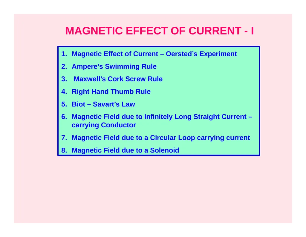
slide2. MAGNETIC EFFECT OF CURRENT - I Magnetic Effect of Current – Oersted’s Experiment
Ampere’s Swimming Rule
Maxwell’s Cork Screw Rule
Right Hand Thumb Rule
Biot – Savart’s Law
Magnetic Field due to Infinitely Long Straight Current – carrying Conductor
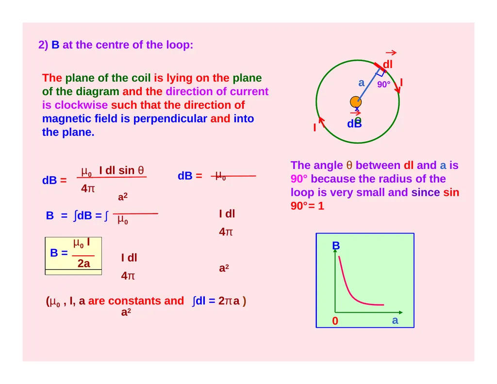
Magnetic Field due to a Circular Loop carrying current
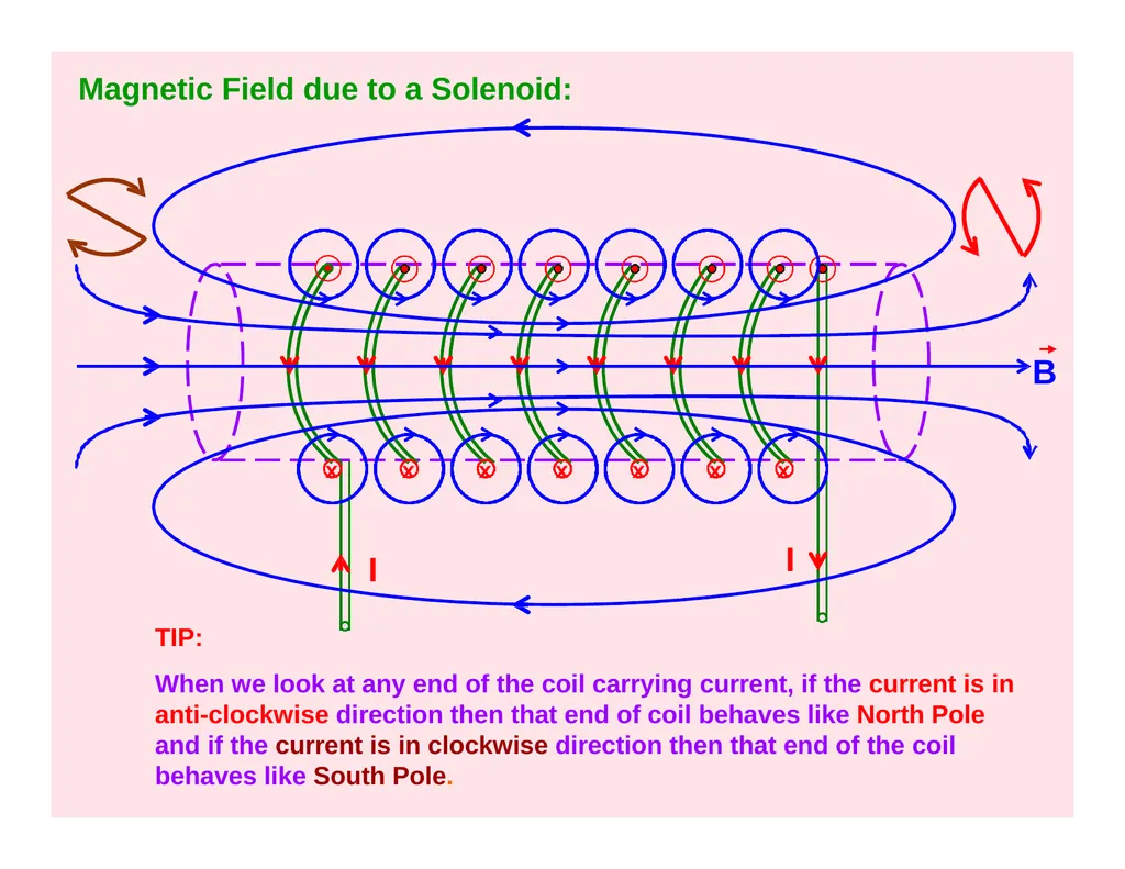
Magnetic Field due to a Solenoid<br>
slide3. N Magnetic Effect of Current:
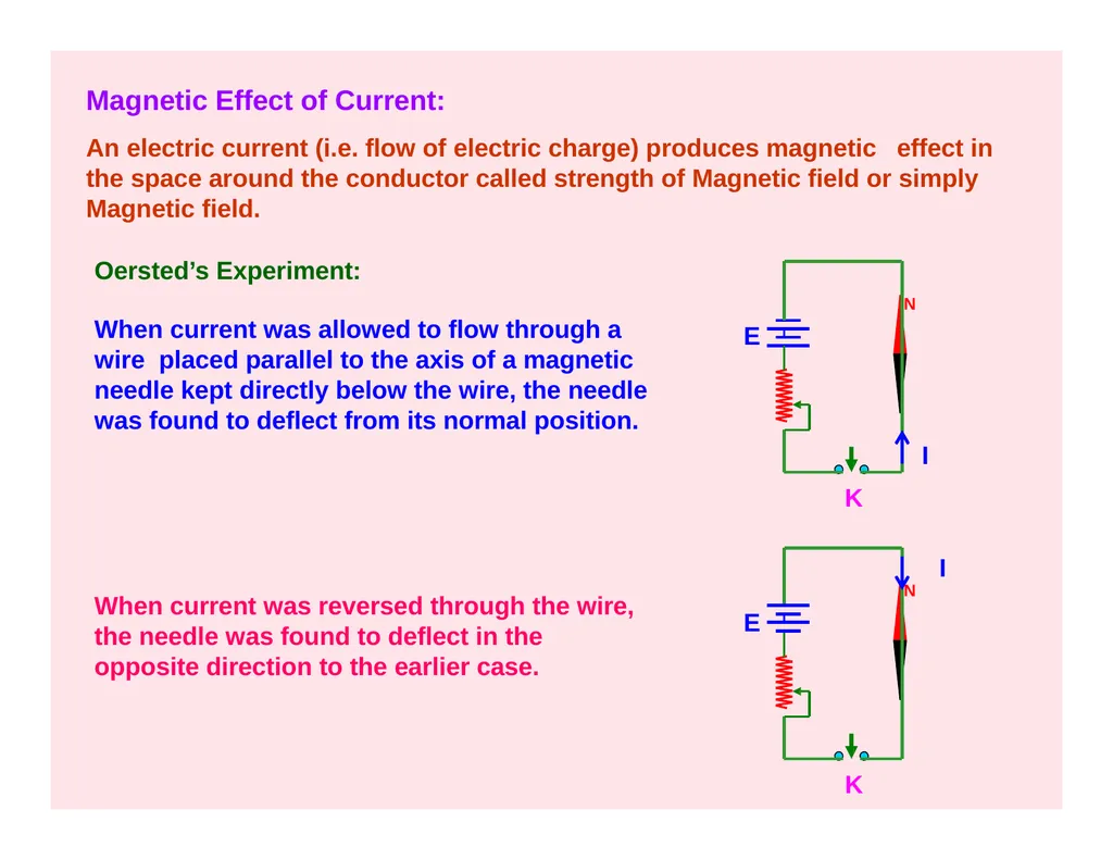
An electric current (i.e. flow of electric charge) produces magnetic effect in the space around the conductor called strength of Magnetic field or simply Magnetic field.
Oersted’s Experiment: When current was allowed to flow through a wire placed parallel to the axis of a magnetic needle kept directly below the wire, the needle was found to deflect from its normal position. E I
K N K I E When current was reversed through the wire, the needle was found to deflect in the opposite direction to the earlier case.<br>
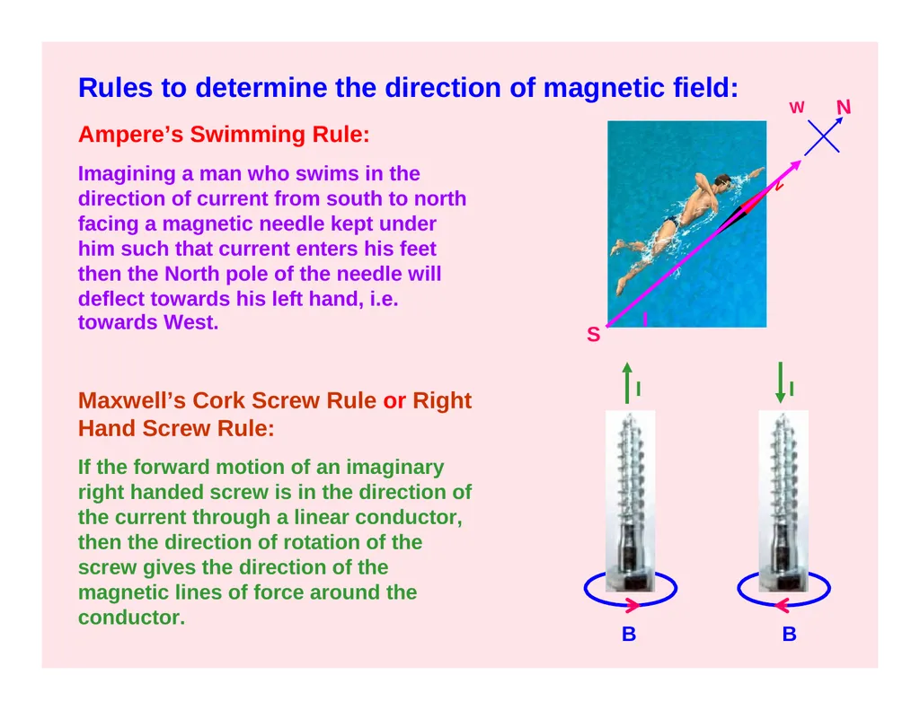
slide4. B B N Rules to determine the direction of magnetic field: Ampere’s Swimming Rule:
Imagining a man who swims in the direction of current from south to north facing a magnetic needle kept under him such that current enters his feet then the North pole of the needle will deflect towards his left hand, i.e. towards West. Maxwell’s Cork Screw Rule or Right Hand Screw Rule:
If the forward motion of an imaginary right handed screw is in the direction of the current through a linear conductor, then the direction of rotation of the screw gives the direction of the magnetic lines of force around the conductor. S N W I I I<br>
slide5. x
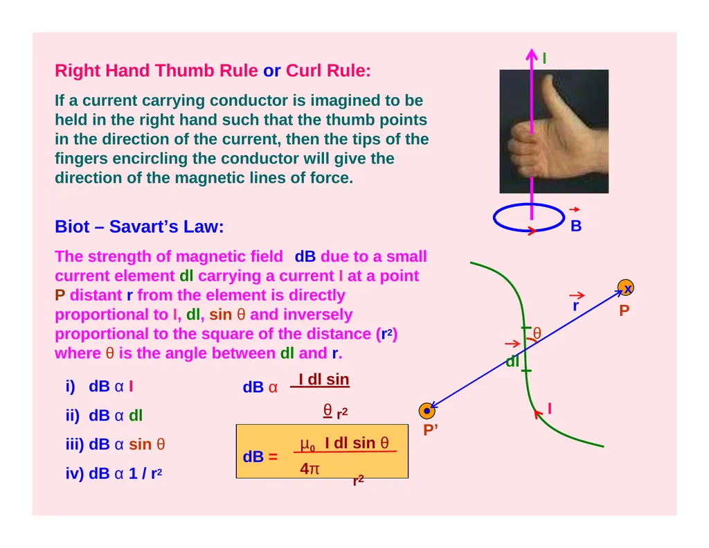
P Right Hand Thumb Rule or Curl Rule:
If a current carrying conductor is imagined to be held in the right hand such that the thumb points in the direction of the current, then the tips of the fingers encircling the conductor will give the direction of the magnetic lines of force. I Biot – Savart’s Law:
The strength of magnetic field dB due to a small current element dl carrying a current I at a point P distant r from the element is directly proportional to I, dl, sin θ and inversely proportional to the square of the distance (r2) where θ is the angle between dl and r. θ dl r dB α I
dB α dl
dB α sin θ
dB α 1 / r2 dB α I dl sin θ r2 dB = µ0 I dl sin θ 4π r2 P’ B I<br>
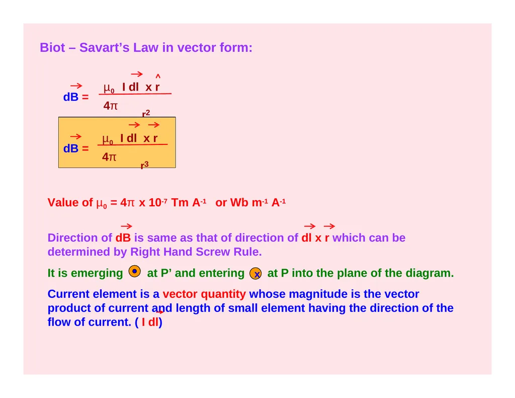
slide6. Biot – Savart’s Law in vector form: dB = µ0 I dl x r 4π r2 dB = µ0 I dl x r 4π r3 Value of µ0 = 4π x 10-7 Tm A-1 or Wb m-1 A-1 Direction of dB is same as that of direction of dl x r which can be determined by Right Hand Screw Rule. It is emerging at P’ and entering at P into the plane of the diagram. Current element is a vector quantity whose magnitude is the vector product of current and length of small element having the direction of the flow of current. ( I dl) x<br>
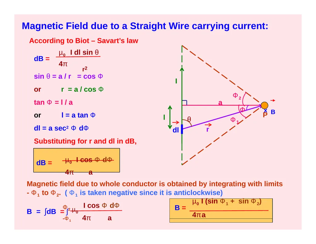
slide7. Magnetic Field due to a Straight Wire carrying current: P θ r a I Ф2 Ф 1 Ф l According to Biot – Savart’s law dB = µ0 I dl sin θ 4π r2 sin θ = a / r = cos Ф or r = a / cos Ф tan Ф = l / a
or l = a tan Ф
dl = a sec2 Ф dФ
Substituting for r and dl in dB, dB = µ0 I cos Ф dФ 4π a Magnetic field due to whole conductor is obtained by integrating with limits
- Ф1 to Ф2. ( Ф1 is taken negative since it is anticlockwise) Ф2 µ0 I cos Ф dФ
-Ф1 4π a B = ∫dB = ∫ µ0 I (sin Ф1 + sin Ф2)
B =
4πa dl x B<br>
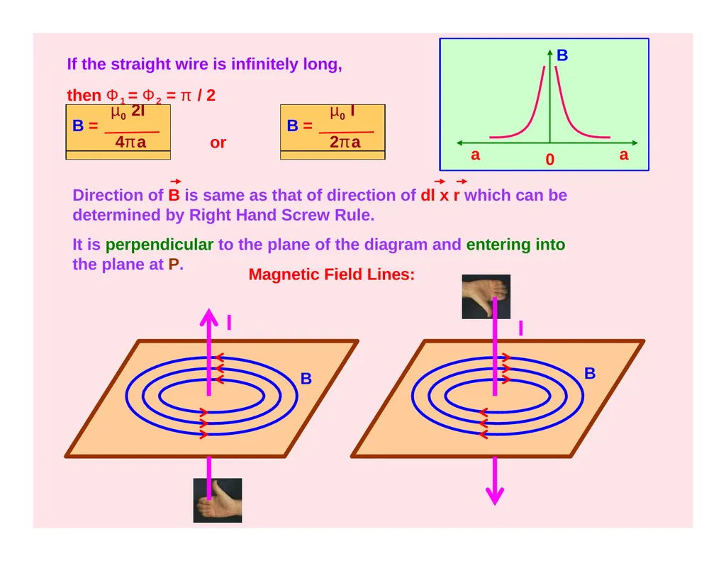
slide8. If the straight wire is infinitely long, then Ф1 = Ф2 = π / 2 µ0 2I
B =
4πa µ0 I
B =
2πa or B a a 0 B B Direction of B is same as that of direction of dl x r which can be determined by Right Hand Screw Rule.
It is perpendicular to the plane of the diagram and entering into the plane at P. Magnetic Field Lines: I I<br>
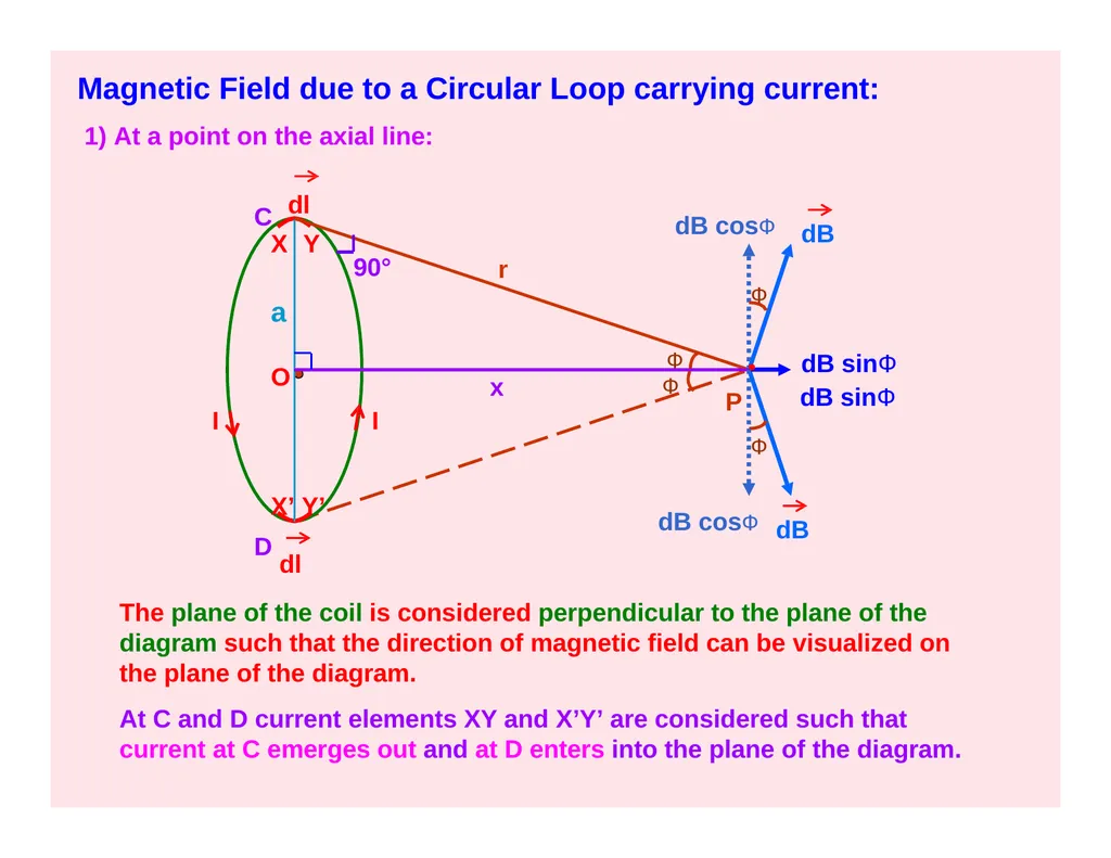
slide9. Magnetic Field due to a Circular Loop carrying current: 1) At a point on the axial line: O a r dB dB dB cosФ dB sinФ dB sinФ I I dl C X Y dl
The plane of the coil is considered perpendicular to the plane of the diagram such that the direction of magnetic field can be visualized on the plane of the diagram.
At C and D current elements XY and X’Y’ are considered such that current at C emerges out and at D enters into the plane of the diagram. X’ Y’ D 90° Ф Ф Ф Ф x P dB cosФ<br>
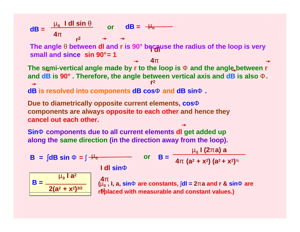
slide10. dB = µ0 I dl sin θ 4π r2 dB = µ0 I dl 4π r2 µ0 I dl sinФ 4π r2 B = ∫dB sin Ф = ∫ or B = µ0 I (2πa) a 4π (a2 + x2) (a2 + x2)½ µ0 I a2
B =
2(a2 + x2)3/2 (µ0 , I, a, sinФ are constants, ∫dl = 2πa and r & sinФ are replaced with measurable and constant values.) or The angle θ between dl and r is 90° because the radius of the loop is very small and since sin 90°= 1
The semi-vertical angle made by r to the loop is Ф and the angle between r and dB is 90° . Therefore, the angle between vertical axis and dB is also Ф.
dB is resolved into components dB cosФ and dB sinФ .
Due to diametrically opposite current elements, cosФ components are always opposite to each other and hence they cancel out each other.
SinФ components due to all current elements dl get added up along the same direction (in the direction away from the loop).<br>
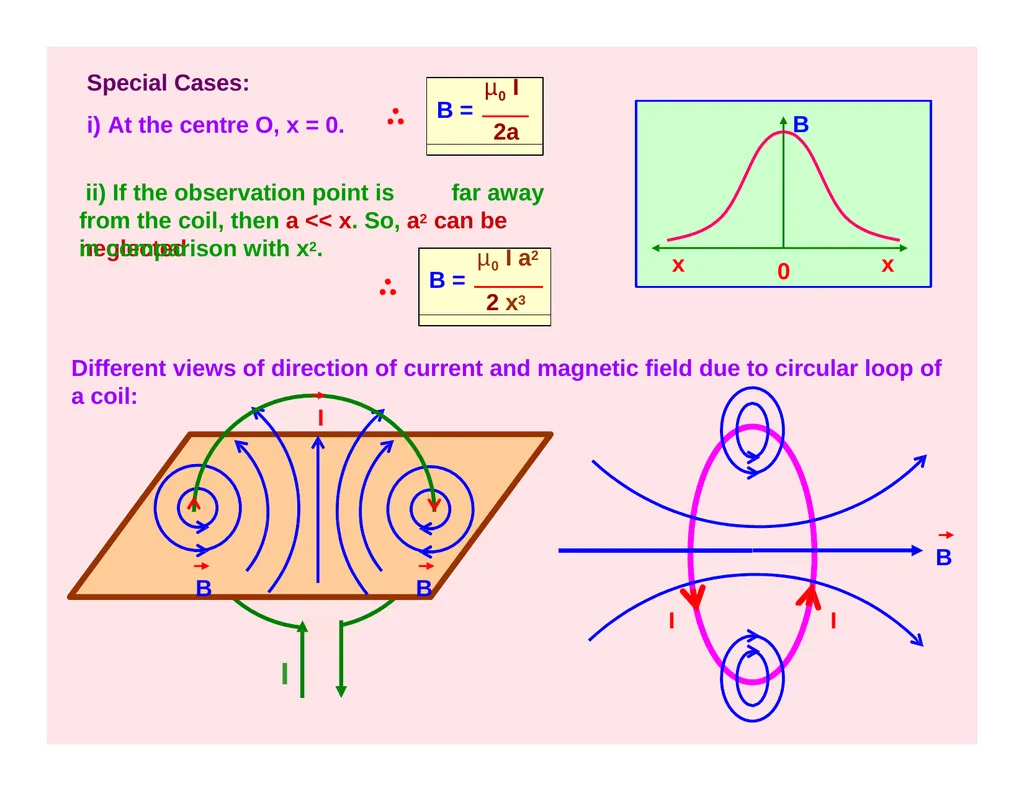
slide11. I I I Different views of direction of current and magnetic field due to circular loop of a coil:
I B x x 0 ii) If the observation point is far away from the coil, then a << x. So, a2 can be neglected in comparison with x2. µ0 I a2
B =
2 x3 Special Cases:
i) At the centre O, x = 0. µ0 I
B =
2a B B B<br>
slide12. dB dB = µ0 I dl sin θ 4π a2
µ0 I dl 4π a2 I dB = µ0 I dl 4π a2 The angle θ between dl and a is 90° because the radius of the loop is very small and since sin 90°= 1 B = ∫dB = ∫ (µ0 , I, a are constants and ∫dl = 2πa ) a
xO 2) B at the centre of the loop: The plane of the coil is lying on the plane of the diagram and the direction of current is clockwise such that the direction of magnetic field is perpendicular and into the plane. I dl
90° µ0 I
B =
2a B a 0<br>
slide13. Magnetic Field due to a Solenoid: I I x x x x x x x TIP:
When we look at any end of the coil carrying current, if the current is in anti-clockwise direction then that end of coil behaves like North Pole and if the current is in clockwise direction then that end of the coil behaves like South Pole. B<br>
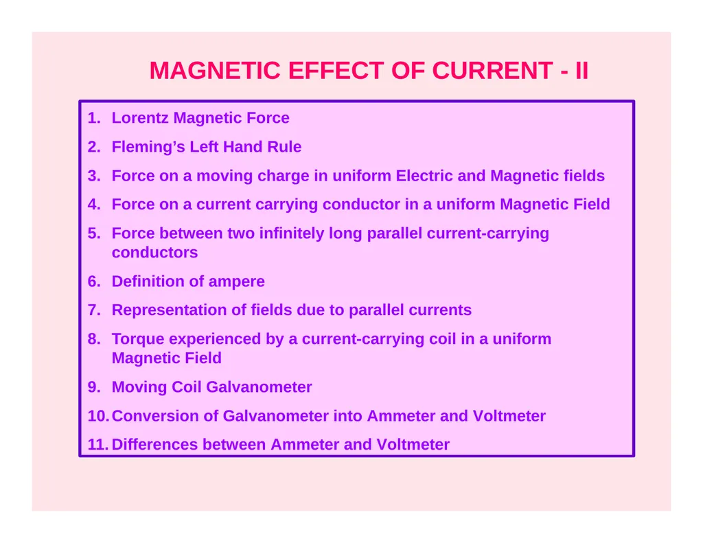
slide14. MAGNETIC EFFECT OF CURRENT - II Lorentz Magnetic Force
Fleming’s Left Hand Rule
Force on a moving charge in uniform Electric and Magnetic fields
Force on a current carrying conductor in a uniform Magnetic Field
Force between two infinitely long parallel current-carrying conductors
Definition of ampere
Representation of fields due to parallel currents
Torque experienced by a current-carrying coil in a uniform Magnetic Field
Moving Coil Galvanometer
Conversion of Galvanometer into Ammeter and Voltmeter
Differences between Ammeter and Voltmeter<br>
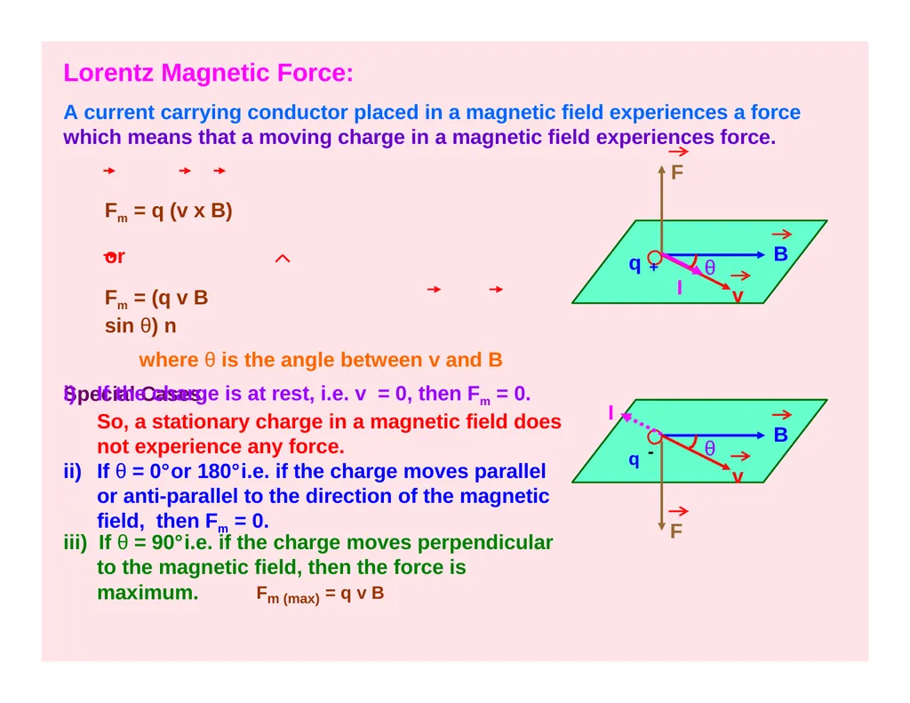
slide15. Lorentz Magnetic Force: A current carrying conductor placed in a magnetic field experiences a force which means that a moving charge in a magnetic field experiences force.
F Fm = q (v x B) or
Fm = (q v B sin θ) n
where θ is the angle between v and B Special Cases: q + B v I θ q - B v F θ If the charge is at rest, i.e. v = 0, then Fm = 0. So, a stationary charge in a magnetic field does not experience any force.
If θ = 0°or 180°i.e. if the charge moves parallel
or anti-parallel to the direction of the magnetic field, then Fm = 0. iii) If θ = 90°i.e. if the charge moves perpendicular to the magnetic field, then the force is maximum. Fm (max) = q v B I<br>
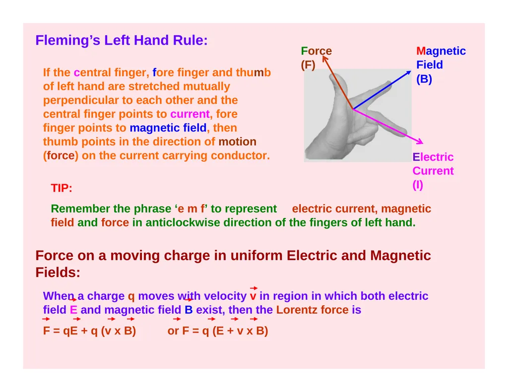
slide16. Fleming’s Left Hand Rule: Force (F) Magnetic Field
(B) Electric Current (I) If the central finger, fore finger and thumb of left hand are stretched mutually perpendicular to each other and the central finger points to current, fore finger points to magnetic field, then thumb points in the direction of motion (force) on the current carrying conductor. TIP:
Remember the phrase ‘e m f’ to represent electric current, magnetic field and force in anticlockwise direction of the fingers of left hand.
Force on a moving charge in uniform Electric and Magnetic Fields:
When a charge q moves with velocity v in region in which both electric field E and magnetic field B exist, then the Lorentz force is
F = qE + q (v x B) or F = q (E + v x B)<br>
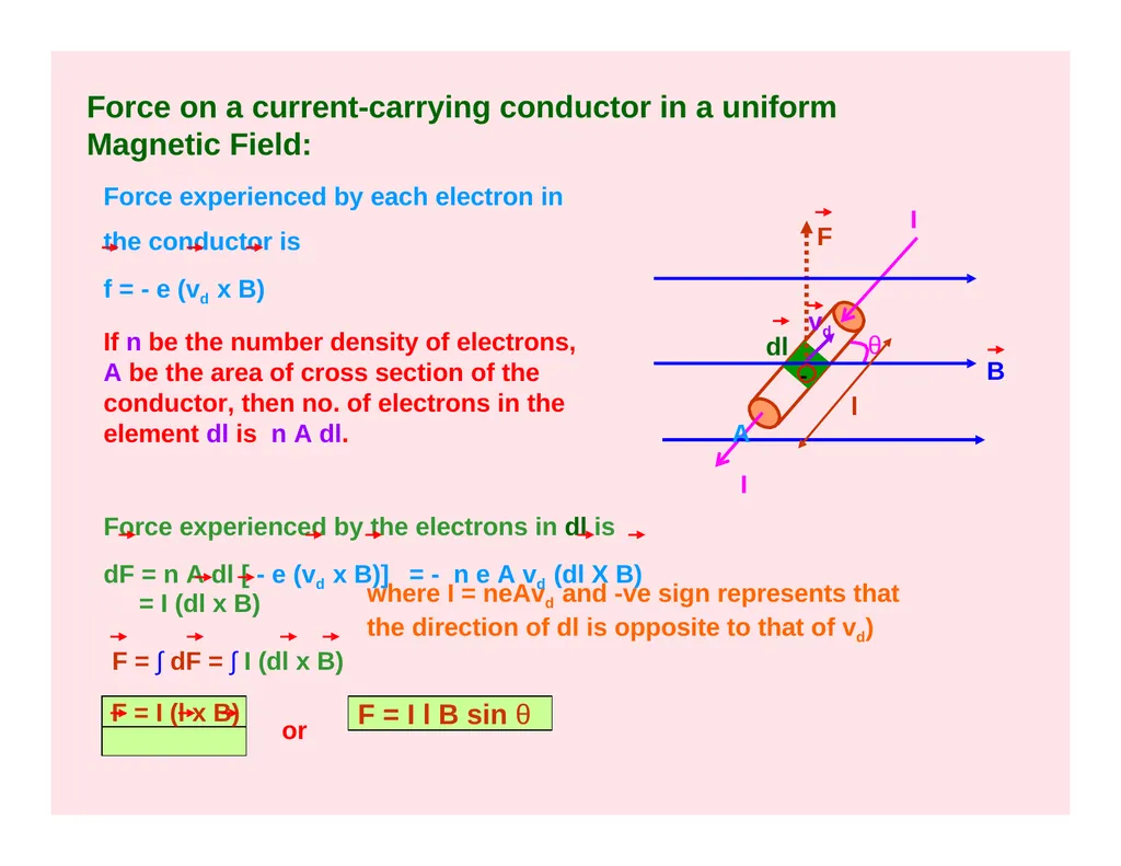
slide17. Force on a current-carrying conductor in a uniform Magnetic Field: θ vd dl F A I I B l Force experienced by each electron in the conductor is f = - e (vd x B) If n be the number density of electrons, A be the area of cross section of the conductor, then no. of electrons in the element dl is n A dl. where I = neAvd and -ve sign represents that the direction of dl is opposite to that of vd) or F = I l B sin θ - Force experienced by the electrons in dl is dF = n A dl [ - e (vd x B)] = - n e A vd (dl X B) = I (dl x B) F = ∫ dF = ∫ I (dl x B) F = I (l x B)<br>
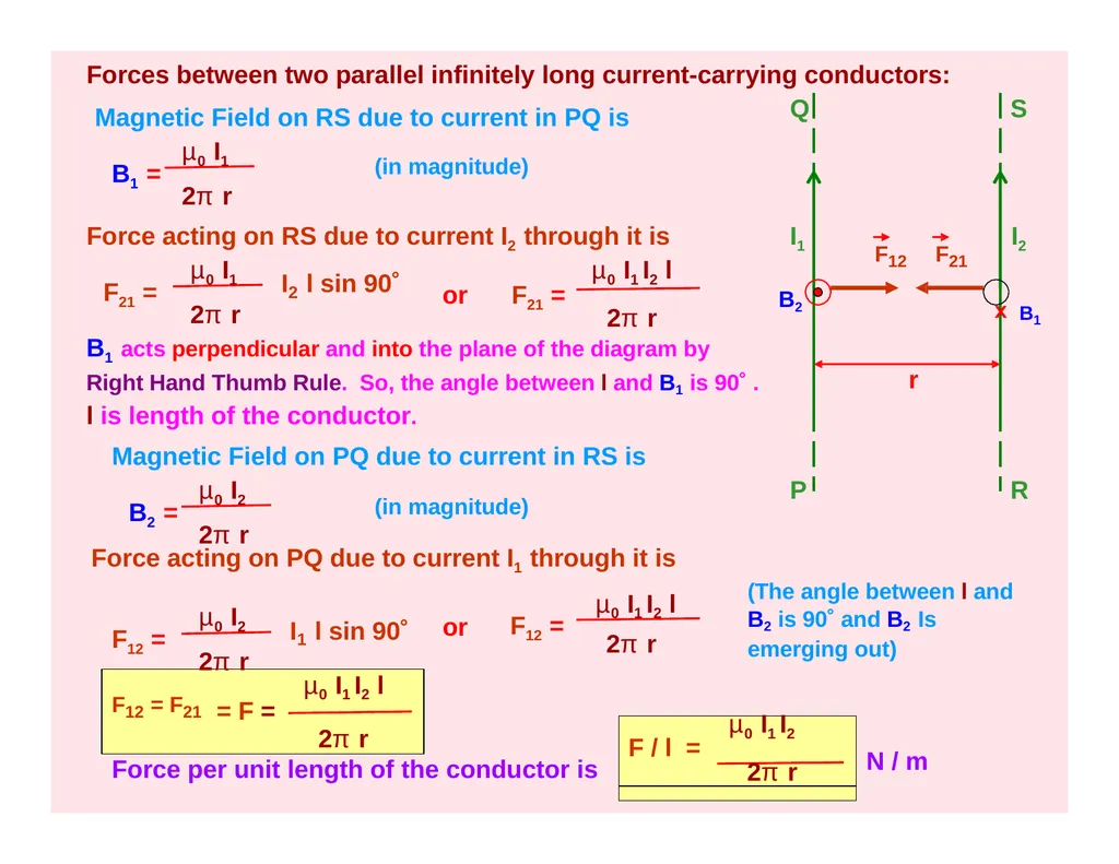
slide18. Forces between two parallel infinitely long current-carrying conductors: r F12 F21 1 2π r I1
B2 P Q I2
x B1 S R B1 = µ0 I1
2π r Magnetic Field on RS due to current in PQ is Force acting on RS due to current I2 through it is F21 = µ0 I1
2π r I l sin 90˚ 2 B1 acts perpendicular and into the plane of the diagram by Right Hand Thumb Rule. So, the angle between l and B1 is 90˚ . l is length of the conductor.
Magnetic Field on PQ due to current in RS is or F21 = µ0 I1 I2 l
2π r B2 = µ0 I2
2π r Force acting on PQ due to current I1 through it is
µ0 I1 I2 l F12 = µ0 I2
2π r I l sin 90˚ F12 = (The angle between l and B2 is 90˚ and B2 Is emerging out) F12 = F21 µ0 I1 I2 l
= F =
2π r µ0 I1 I2
F / l =
2π r or Force per unit length of the conductor is N / m (in magnitude) (in magnitude)<br>
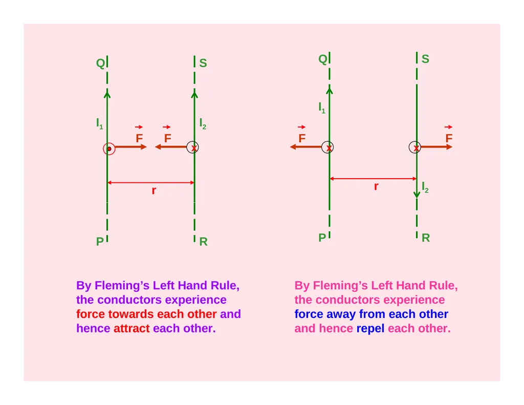
slide19. r F F I1 P Q I2 x S R r I2 F x S R I1 F P Q x By Fleming’s Left Hand Rule, the conductors experience force towards each other and hence attract each other. By Fleming’s Left Hand Rule, the conductors experience force away from each other and hence repel each other.<br>
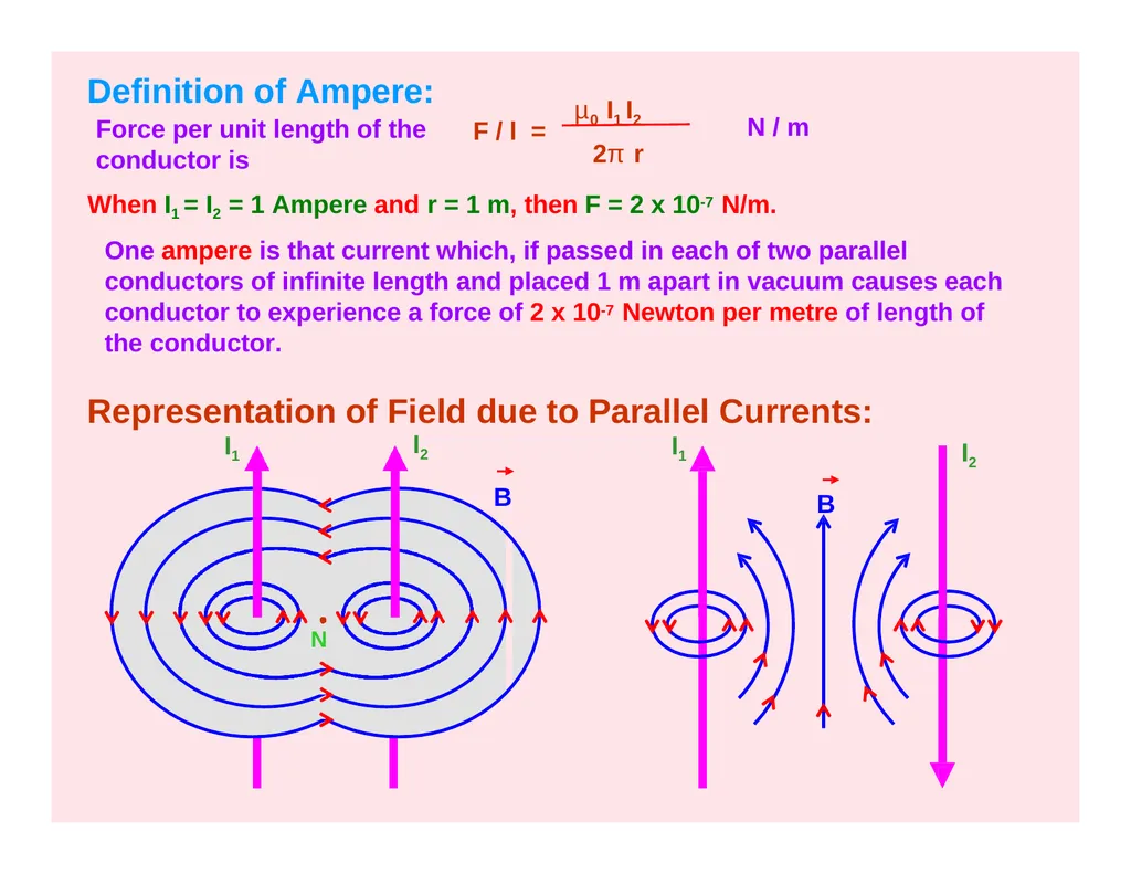
slide20. Definition of Ampere:
Force per unit length of the conductor is F / l = µ0 I1 I2
2π r N / m When I1 = I2 = 1 Ampere and r = 1 m, then F = 2 x 10⁻⁷ N/m.
One ampere is that current which, if passed in each of two parallel conductors of infinite length and placed 1 m apart in vacuum causes each conductor to experience a force of 2 x 10⁻⁷ Newton per metre of length of the conductor.
Representation of Field due to Parallel Currents: I1 I1 I2 B I2 B N<br>
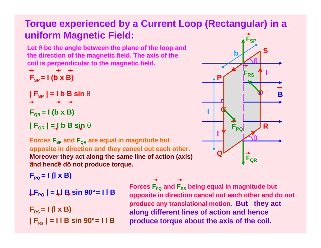
slide21. B Torque experienced by a Current Loop (Rectangular) in a uniform Magnetic Field: P Q R S x θ l I | FPQ | = I l B sin 90°= I l B FRS = I (l x B)
| FRs | = I l B sin 90°= I l B Forces FPQ and FRS being equal in magnitude but opposite in direction cancel out each other and do not produce any translational motion. But they act along different lines of action and hence produce torque about the axis of the coil. FQR θ
FRS Let θ be the angle between the plane of the loop and the direction of the magnetic field. The axis of the coil is perpendicular to the magnetic field. b I FSP = I (b x B)
| FSP | = I b B sin θ
FQR = I (b x B)
| FQR | = I b B sin θ
Forces FSP and FQR are equal in magnitude but opposite in direction and they cancel out each other. Moreover they act along the same line of action (axis) and hence do not produce torque.
FPQ = I (l x B) FSP F PQ<br>
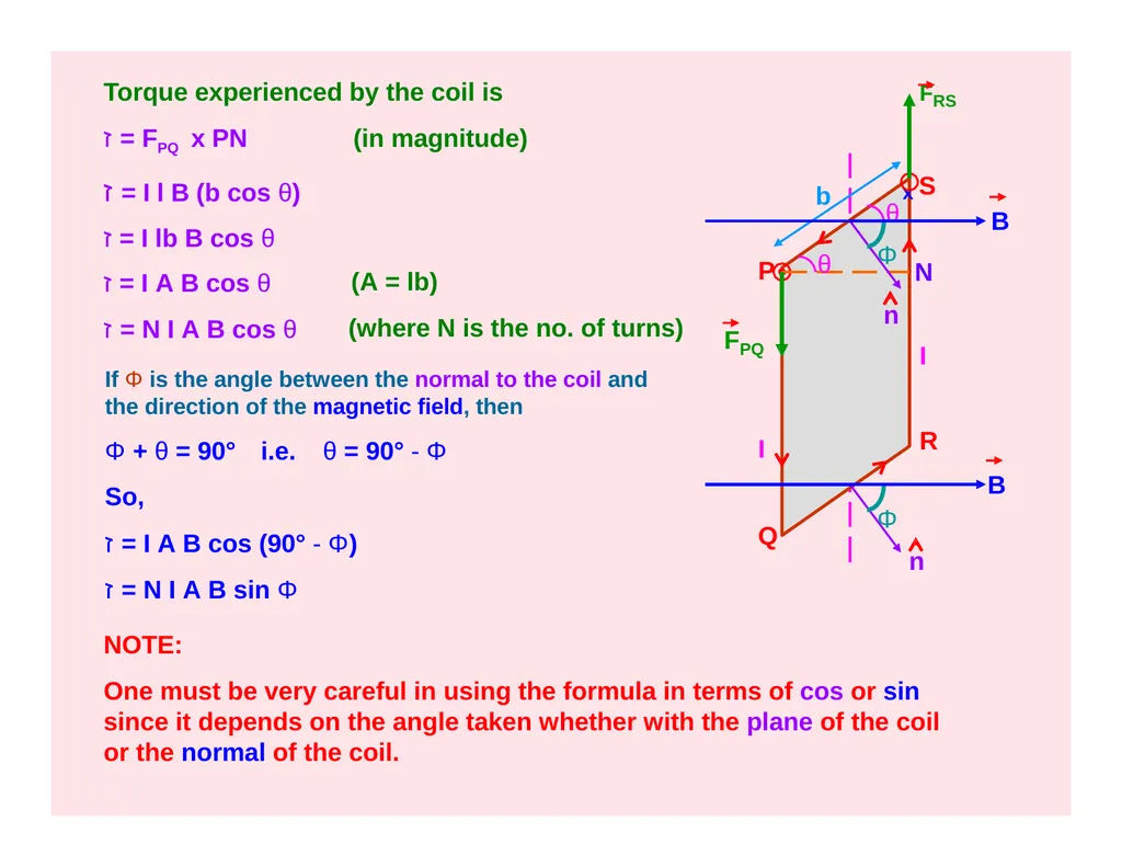
slide22. P Q R x S b θ θ N Torque experienced by the coil is ז = FPQ x PN
ז = I l B (b cos θ) ז = I lb B cos θ ז = I A B cos θ
ז = N I A B cos θ (in magnitude) (A = lb)
(where N is the no. of turns) If Φ is the angle between the normal to the coil and the direction of the magnetic field, then
Φ + θ = 90° i.e. θ = 90° - Φ
So, ז = I A B cos (90° - Φ)
ז = N I A B sin Φ NOTE:
One must be very careful in using the formula in terms of cos or sin since it depends on the angle taken whether with the plane of the coil or the normal of the coil. Φ Φ B B F PQ FRS n n I I<br>
slide23. (since M = I A is the Magnetic Dipole Moment)
Note: The coil will rotate in the anticlockwise direction (from the top view, according to the figure) about the axis of the coil shown by the dotted line.
The torque acts in the upward direction along the dotted line (according to Maxwell’s Screw Rule).
3) If Φ = 0°, then ז = 0.
4)
5)
6) If Φ = 90°, then ז is maximum. i.e. ז max = N I A B Units: B in Tesla, I in Ampere, A in m2 and ז in Nm.
The above formulae for torque can be used for any loop irrespective of its shape. or ז = N I (A x B) ז = N (M x B) Torque in Vector form:
ז = N I A B sin Φ ז = (N I A B sin Φ) n (where n is unit vector normal to the plane of the loop)<br>
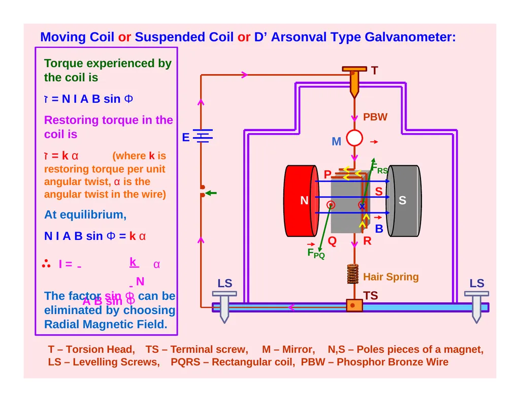
slide24. PBW P T – Torsion Head, TS – Terminal screw, M – Mirror, N,S – Poles pieces of a magnet, LS – Levelling Screws, PQRS – Rectangular coil, PBW – Phosphor Bronze Wire LS FRS S Q R Moving Coil or Suspended Coil or D’ Arsonval Type Galvanometer: N S x T E LS B Torque experienced by the coil is
ז = N I A B sin Φ
Restoring torque in the coil is ז = k α (where k is restoring torque per unit angular twist, α is the angular twist in the wire)
At equilibrium,
N I A B sin Φ = k α I = k N A B sin Φ α The factor sin Φ can be eliminated by choosing Radial Magnetic Field. M Hair Spring
TS FPQ<br>
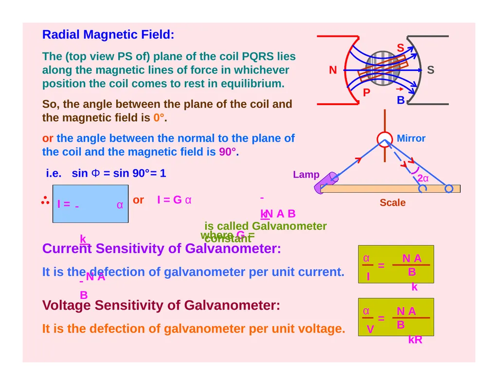
slide25. Lamp Scale Radial Magnetic Field:
The (top view PS of) plane of the coil PQRS lies along the magnetic lines of force in whichever position the coil comes to rest in equilibrium.
So, the angle between the plane of the coil and the magnetic field is 0°.
or the angle between the normal to the plane of the coil and the magnetic field is 90°. N S B P S i.e. sin Φ = sin 90°= 1 I = k N A B α or I = G α k
where G = N A B
is called Galvanometer constant Current Sensitivity of Galvanometer:
It is the defection of galvanometer per unit current. N A B
k α
I = Voltage Sensitivity of Galvanometer:
It is the defection of galvanometer per unit voltage. N A B
kR α
V = Mirror 2α<br>
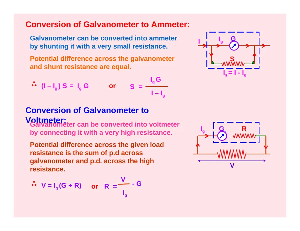
slide26. Conversion of Galvanometer to Ammeter: Galvanometer can be converted into ammeter by shunting it with a very small resistance.
Potential difference across the galvanometer and shunt resistance are equal. (I – Ig ) S = Ig G S = Ig G I – Ig
Conversion of Galvanometer to Voltmeter: Galvanometer can be converted into voltmeter by connecting it with a very high resistance.
Potential difference across the given load resistance is the sum of p.d across galvanometer and p.d. across the high resistance. V = Ig (G + R) G I Ig Is = I - Ig S or R = V
Ig - G Ig G R V or<br>
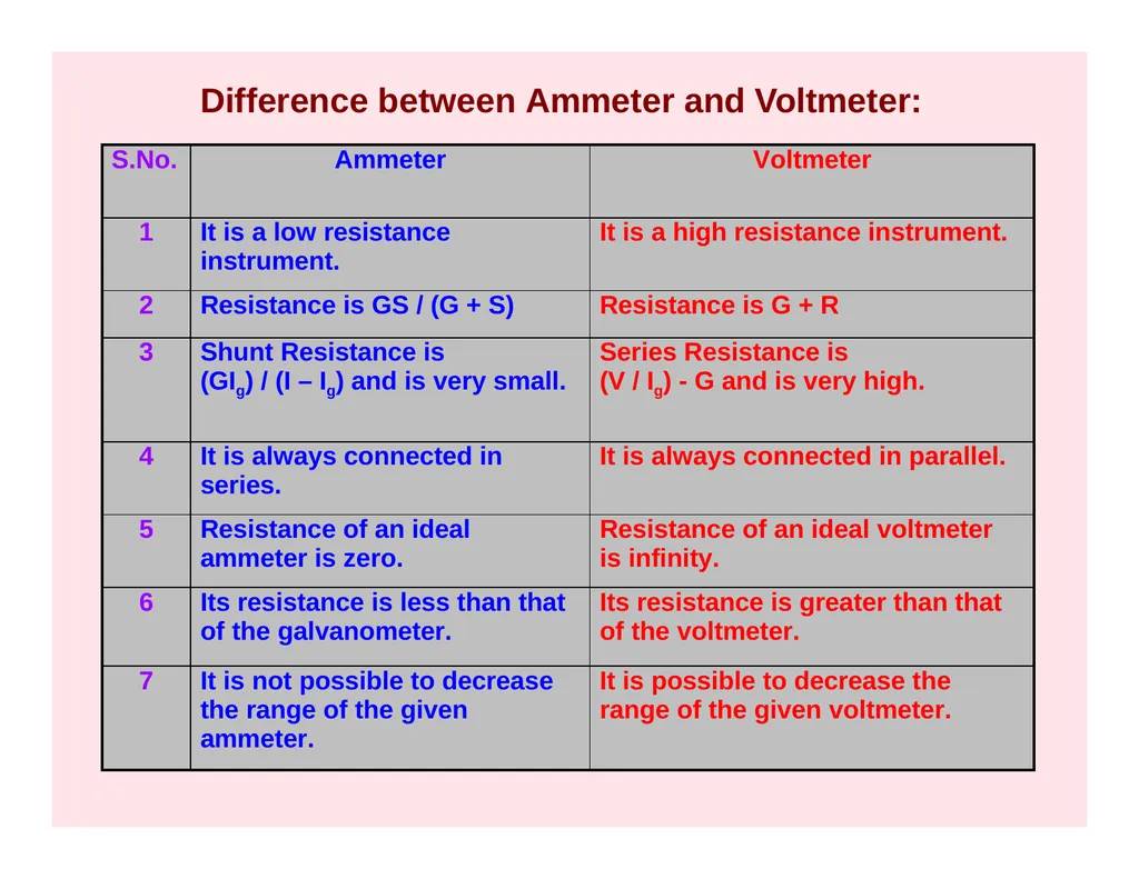
slide27. Difference between Ammeter and Voltmeter:<br>
slide28. MAGNETIC EFFECT OF CURRENT - III Cyclotron
Ampere’s Circuital Law
Magnetic Field due to a Straight Solenoid
Magnetic Field due to a Toroidal Solenoid<br>
slide29. N
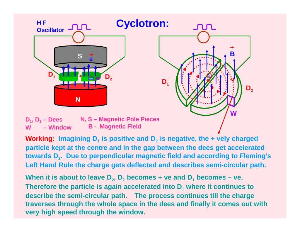
W S D1 D2 + B Cyclotron: D1, D2 – Dees
W – Window N, S – Magnetic Pole Pieces B - Magnetic Field H F
Oscillator D2 D1 Working: Imagining D1 is positive and D2 is negative, the + vely charged particle kept at the centre and in the gap between the dees get accelerated towards D2. Due to perpendicular magnetic field and according to Fleming’s Left Hand Rule the charge gets deflected and describes semi-circular path.
When it is about to leave D2, D2 becomes + ve and D1 becomes – ve. Therefore the particle is again accelerated into D1 where it continues to describe the semi-circular path. The process continues till the charge traverses through the whole space in the dees and finally it comes out with very high speed through the window. W B<br>
slide30. Theory:
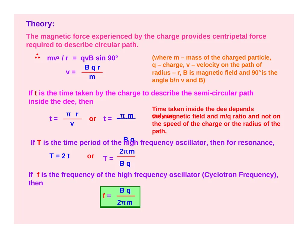
The magnetic force experienced by the charge provides centripetal force required to describe circular path. mv2 / r = qvB sin 90° (where m – mass of the charged particle, q – charge, v – velocity on the path of
radius – r, B is magnetic field and 90°is the angle b/n v and B) v = B q r m If t is the time taken by the charge to describe the semi-circular path inside the dee, then
Time taken inside the dee depends only on t = π r v or t = π m B q the magnetic field and m/q ratio and not on the speed of the charge or the radius of the path. If T is the time period of the high frequency oscillator, then for resonance, T = 2 t or T = 2πm B q If f is the frequency of the high frequency oscillator (Cyclotron Frequency), then B q
f =
2πm<br>
slide31. Maximum Energy of the Particle:
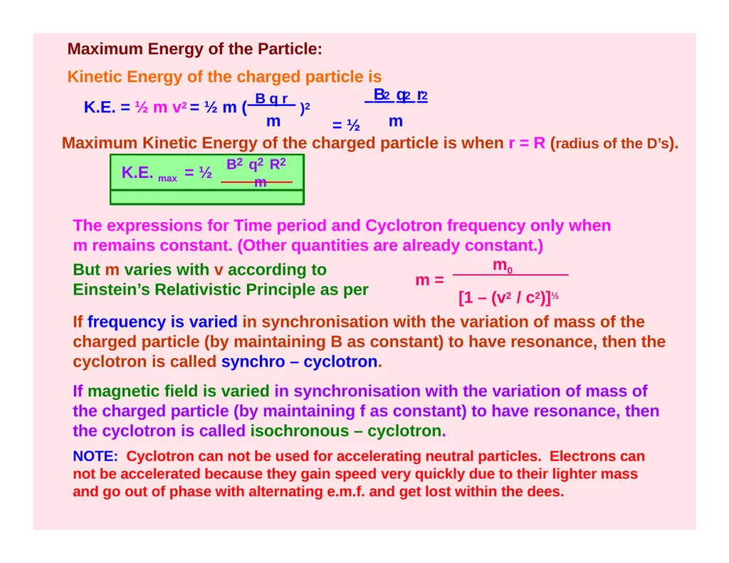
Kinetic Energy of the charged particle is
2 2 2 K.E. = ½ m v2 = ½ m ( B q r )2 m m B q r
= ½ Maximum Kinetic Energy of the charged particle is when r = R (radius of the D’s). B2 q2 R2
K.E. max = ½ m The expressions for Time period and Cyclotron frequency only when m remains constant. (Other quantities are already constant.) m = m0 [1 – (v2 / c2)]½ If frequency is varied in synchronisation with the variation of mass of the charged particle (by maintaining B as constant) to have resonance, then the cyclotron is called synchro – cyclotron.
If magnetic field is varied in synchronisation with the variation of mass of the charged particle (by maintaining f as constant) to have resonance, then the cyclotron is called isochronous – cyclotron.
NOTE: Cyclotron can not be used for accelerating neutral particles. Electrons can not be accelerated because they gain speed very quickly due to their lighter mass and go out of phase with alternating e.m.f. and get lost within the dees. But m varies with v according to Einstein’s Relativistic Principle as per<br>
slide32. Ampere’s Circuital Law:
The line integral ∫ B . dl for a closed curve is equal to µ0 times the net current I threading through the area bounded by the curve. ∫ B . dl = µ0 I ∫ B . dl = ∫ B . dl cos 0°
= ∫ B . dl = B ∫ dl = B (2π r) = ( µ0 I / 2π r) x 2π r ∫ B . dl = µ0 I I B B r O dl I Current is emerging out and the magnetic field is anticlockwise. Proof:<br>
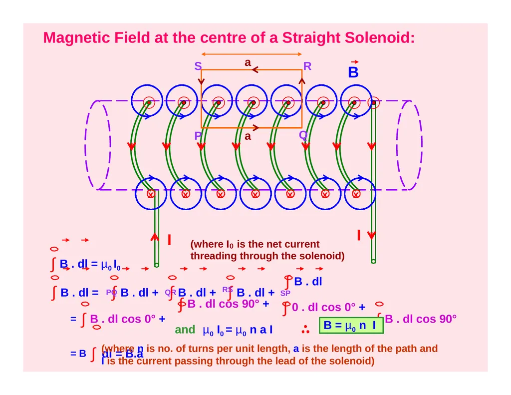
slide33. Magnetic Field at the centre of a Straight Solenoid: I I x x x x x x x P Q S R ∫ B . dl = µ0 I0 (where I is the net current 0
threading through the solenoid) ∫ B . dl = ∫ B . dl + PQ QR ∫ B . dl + ∫ B . dl + RS
∫ B . dl cos 90° + ∫ B . dl
SP
∫ 0 . dl cos 0° + B = ∫ B . dl cos 0° +
= B ∫ dl = B.a ∫ B . dl cos 90° and µ0 I0 = µ0 n a I (where n is no. of turns per unit length, a is the length of the path and I is the current passing through the lead of the solenoid) a a B = µ0 n I<br>
slide34. Magnetic Field due to Toroidal Solenoid (Toroid): I dl B O B = 0 B = 0 Q P
B ≠ 0 ∫ B . dl = µ0 I0 ∫ B . dl cos 0° = B ∫ dl = B (2π r) And µ0 I0 = µ0 n (2π r) I r B = µ0 n I ∫ B . dl = NOTE:
The magnetic field exists only in the tubular area bound by the coil and it does not exist in the area inside and outside the toroid.
i.e. B is zero at O and Q and non-zero at P.<br>
SUBJECT- PHYSICS
CHAPTER- MOVING CHARGES AND MAGNETISM<br>
slide2. MAGNETIC EFFECT OF CURRENT - I Magnetic Effect of Current – Oersted’s Experiment
Ampere’s Swimming Rule
Maxwell’s Cork Screw Rule
Right Hand Thumb Rule
Biot – Savart’s Law
Magnetic Field due to Infinitely Long Straight Current – carrying Conductor
Magnetic Field due to a Circular Loop carrying current
Magnetic Field due to a Solenoid<br>
slide3. N Magnetic Effect of Current:
An electric current (i.e. flow of electric charge) produces magnetic effect in the space around the conductor called strength of Magnetic field or simply Magnetic field.
Oersted’s Experiment: When current was allowed to flow through a wire placed parallel to the axis of a magnetic needle kept directly below the wire, the needle was found to deflect from its normal position. E I
K N K I E When current was reversed through the wire, the needle was found to deflect in the opposite direction to the earlier case.<br>
slide4. B B N Rules to determine the direction of magnetic field: Ampere’s Swimming Rule:
Imagining a man who swims in the direction of current from south to north facing a magnetic needle kept under him such that current enters his feet then the North pole of the needle will deflect towards his left hand, i.e. towards West. Maxwell’s Cork Screw Rule or Right Hand Screw Rule:
If the forward motion of an imaginary right handed screw is in the direction of the current through a linear conductor, then the direction of rotation of the screw gives the direction of the magnetic lines of force around the conductor. S N W I I I<br>
slide5. x
P Right Hand Thumb Rule or Curl Rule:
If a current carrying conductor is imagined to be held in the right hand such that the thumb points in the direction of the current, then the tips of the fingers encircling the conductor will give the direction of the magnetic lines of force. I Biot – Savart’s Law:
The strength of magnetic field dB due to a small current element dl carrying a current I at a point P distant r from the element is directly proportional to I, dl, sin θ and inversely proportional to the square of the distance (r2) where θ is the angle between dl and r. θ dl r dB α I
dB α dl
dB α sin θ
dB α 1 / r2 dB α I dl sin θ r2 dB = µ0 I dl sin θ 4π r2 P’ B I<br>
slide6. Biot – Savart’s Law in vector form: dB = µ0 I dl x r 4π r2 dB = µ0 I dl x r 4π r3 Value of µ0 = 4π x 10-7 Tm A-1 or Wb m-1 A-1 Direction of dB is same as that of direction of dl x r which can be determined by Right Hand Screw Rule. It is emerging at P’ and entering at P into the plane of the diagram. Current element is a vector quantity whose magnitude is the vector product of current and length of small element having the direction of the flow of current. ( I dl) x<br>
slide7. Magnetic Field due to a Straight Wire carrying current: P θ r a I Ф2 Ф 1 Ф l According to Biot – Savart’s law dB = µ0 I dl sin θ 4π r2 sin θ = a / r = cos Ф or r = a / cos Ф tan Ф = l / a
or l = a tan Ф
dl = a sec2 Ф dФ
Substituting for r and dl in dB, dB = µ0 I cos Ф dФ 4π a Magnetic field due to whole conductor is obtained by integrating with limits
- Ф1 to Ф2. ( Ф1 is taken negative since it is anticlockwise) Ф2 µ0 I cos Ф dФ
-Ф1 4π a B = ∫dB = ∫ µ0 I (sin Ф1 + sin Ф2)
B =
4πa dl x B<br>
slide8. If the straight wire is infinitely long, then Ф1 = Ф2 = π / 2 µ0 2I
B =
4πa µ0 I
B =
2πa or B a a 0 B B Direction of B is same as that of direction of dl x r which can be determined by Right Hand Screw Rule.
It is perpendicular to the plane of the diagram and entering into the plane at P. Magnetic Field Lines: I I<br>
slide9. Magnetic Field due to a Circular Loop carrying current: 1) At a point on the axial line: O a r dB dB dB cosФ dB sinФ dB sinФ I I dl C X Y dl
The plane of the coil is considered perpendicular to the plane of the diagram such that the direction of magnetic field can be visualized on the plane of the diagram.
At C and D current elements XY and X’Y’ are considered such that current at C emerges out and at D enters into the plane of the diagram. X’ Y’ D 90° Ф Ф Ф Ф x P dB cosФ<br>
slide10. dB = µ0 I dl sin θ 4π r2 dB = µ0 I dl 4π r2 µ0 I dl sinФ 4π r2 B = ∫dB sin Ф = ∫ or B = µ0 I (2πa) a 4π (a2 + x2) (a2 + x2)½ µ0 I a2
B =
2(a2 + x2)3/2 (µ0 , I, a, sinФ are constants, ∫dl = 2πa and r & sinФ are replaced with measurable and constant values.) or The angle θ between dl and r is 90° because the radius of the loop is very small and since sin 90°= 1
The semi-vertical angle made by r to the loop is Ф and the angle between r and dB is 90° . Therefore, the angle between vertical axis and dB is also Ф.
dB is resolved into components dB cosФ and dB sinФ .
Due to diametrically opposite current elements, cosФ components are always opposite to each other and hence they cancel out each other.
SinФ components due to all current elements dl get added up along the same direction (in the direction away from the loop).<br>
slide11. I I I Different views of direction of current and magnetic field due to circular loop of a coil:
I B x x 0 ii) If the observation point is far away from the coil, then a << x. So, a2 can be neglected in comparison with x2. µ0 I a2
B =
2 x3 Special Cases:
i) At the centre O, x = 0. µ0 I
B =
2a B B B<br>
slide12. dB dB = µ0 I dl sin θ 4π a2
µ0 I dl 4π a2 I dB = µ0 I dl 4π a2 The angle θ between dl and a is 90° because the radius of the loop is very small and since sin 90°= 1 B = ∫dB = ∫ (µ0 , I, a are constants and ∫dl = 2πa ) a
xO 2) B at the centre of the loop: The plane of the coil is lying on the plane of the diagram and the direction of current is clockwise such that the direction of magnetic field is perpendicular and into the plane. I dl
90° µ0 I
B =
2a B a 0<br>
slide13. Magnetic Field due to a Solenoid: I I x x x x x x x TIP:
When we look at any end of the coil carrying current, if the current is in anti-clockwise direction then that end of coil behaves like North Pole and if the current is in clockwise direction then that end of the coil behaves like South Pole. B<br>
slide14. MAGNETIC EFFECT OF CURRENT - II Lorentz Magnetic Force
Fleming’s Left Hand Rule
Force on a moving charge in uniform Electric and Magnetic fields
Force on a current carrying conductor in a uniform Magnetic Field
Force between two infinitely long parallel current-carrying conductors
Definition of ampere
Representation of fields due to parallel currents
Torque experienced by a current-carrying coil in a uniform Magnetic Field
Moving Coil Galvanometer
Conversion of Galvanometer into Ammeter and Voltmeter
Differences between Ammeter and Voltmeter<br>
slide15. Lorentz Magnetic Force: A current carrying conductor placed in a magnetic field experiences a force which means that a moving charge in a magnetic field experiences force.
F Fm = q (v x B) or
Fm = (q v B sin θ) n
where θ is the angle between v and B Special Cases: q + B v I θ q - B v F θ If the charge is at rest, i.e. v = 0, then Fm = 0. So, a stationary charge in a magnetic field does not experience any force.
If θ = 0°or 180°i.e. if the charge moves parallel
or anti-parallel to the direction of the magnetic field, then Fm = 0. iii) If θ = 90°i.e. if the charge moves perpendicular to the magnetic field, then the force is maximum. Fm (max) = q v B I<br>
slide16. Fleming’s Left Hand Rule: Force (F) Magnetic Field
(B) Electric Current (I) If the central finger, fore finger and thumb of left hand are stretched mutually perpendicular to each other and the central finger points to current, fore finger points to magnetic field, then thumb points in the direction of motion (force) on the current carrying conductor. TIP:
Remember the phrase ‘e m f’ to represent electric current, magnetic field and force in anticlockwise direction of the fingers of left hand.
Force on a moving charge in uniform Electric and Magnetic Fields:
When a charge q moves with velocity v in region in which both electric field E and magnetic field B exist, then the Lorentz force is
F = qE + q (v x B) or F = q (E + v x B)<br>
slide17. Force on a current-carrying conductor in a uniform Magnetic Field: θ vd dl F A I I B l Force experienced by each electron in the conductor is f = - e (vd x B) If n be the number density of electrons, A be the area of cross section of the conductor, then no. of electrons in the element dl is n A dl. where I = neAvd and -ve sign represents that the direction of dl is opposite to that of vd) or F = I l B sin θ - Force experienced by the electrons in dl is dF = n A dl [ - e (vd x B)] = - n e A vd (dl X B) = I (dl x B) F = ∫ dF = ∫ I (dl x B) F = I (l x B)<br>
slide18. Forces between two parallel infinitely long current-carrying conductors: r F12 F21 1 2π r I1
B2 P Q I2
x B1 S R B1 = µ0 I1
2π r Magnetic Field on RS due to current in PQ is Force acting on RS due to current I2 through it is F21 = µ0 I1
2π r I l sin 90˚ 2 B1 acts perpendicular and into the plane of the diagram by Right Hand Thumb Rule. So, the angle between l and B1 is 90˚ . l is length of the conductor.
Magnetic Field on PQ due to current in RS is or F21 = µ0 I1 I2 l
2π r B2 = µ0 I2
2π r Force acting on PQ due to current I1 through it is
µ0 I1 I2 l F12 = µ0 I2
2π r I l sin 90˚ F12 = (The angle between l and B2 is 90˚ and B2 Is emerging out) F12 = F21 µ0 I1 I2 l
= F =
2π r µ0 I1 I2
F / l =
2π r or Force per unit length of the conductor is N / m (in magnitude) (in magnitude)<br>
slide19. r F F I1 P Q I2 x S R r I2 F x S R I1 F P Q x By Fleming’s Left Hand Rule, the conductors experience force towards each other and hence attract each other. By Fleming’s Left Hand Rule, the conductors experience force away from each other and hence repel each other.<br>
slide20. Definition of Ampere:
Force per unit length of the conductor is F / l = µ0 I1 I2
2π r N / m When I1 = I2 = 1 Ampere and r = 1 m, then F = 2 x 10⁻⁷ N/m.
One ampere is that current which, if passed in each of two parallel conductors of infinite length and placed 1 m apart in vacuum causes each conductor to experience a force of 2 x 10⁻⁷ Newton per metre of length of the conductor.
Representation of Field due to Parallel Currents: I1 I1 I2 B I2 B N<br>
slide21. B Torque experienced by a Current Loop (Rectangular) in a uniform Magnetic Field: P Q R S x θ l I | FPQ | = I l B sin 90°= I l B FRS = I (l x B)
| FRs | = I l B sin 90°= I l B Forces FPQ and FRS being equal in magnitude but opposite in direction cancel out each other and do not produce any translational motion. But they act along different lines of action and hence produce torque about the axis of the coil. FQR θ
FRS Let θ be the angle between the plane of the loop and the direction of the magnetic field. The axis of the coil is perpendicular to the magnetic field. b I FSP = I (b x B)
| FSP | = I b B sin θ
FQR = I (b x B)
| FQR | = I b B sin θ
Forces FSP and FQR are equal in magnitude but opposite in direction and they cancel out each other. Moreover they act along the same line of action (axis) and hence do not produce torque.
FPQ = I (l x B) FSP F PQ<br>
slide22. P Q R x S b θ θ N Torque experienced by the coil is ז = FPQ x PN
ז = I l B (b cos θ) ז = I lb B cos θ ז = I A B cos θ
ז = N I A B cos θ (in magnitude) (A = lb)
(where N is the no. of turns) If Φ is the angle between the normal to the coil and the direction of the magnetic field, then
Φ + θ = 90° i.e. θ = 90° - Φ
So, ז = I A B cos (90° - Φ)
ז = N I A B sin Φ NOTE:
One must be very careful in using the formula in terms of cos or sin since it depends on the angle taken whether with the plane of the coil or the normal of the coil. Φ Φ B B F PQ FRS n n I I<br>
slide23. (since M = I A is the Magnetic Dipole Moment)
Note: The coil will rotate in the anticlockwise direction (from the top view, according to the figure) about the axis of the coil shown by the dotted line.
The torque acts in the upward direction along the dotted line (according to Maxwell’s Screw Rule).
3) If Φ = 0°, then ז = 0.
4)
5)
6) If Φ = 90°, then ז is maximum. i.e. ז max = N I A B Units: B in Tesla, I in Ampere, A in m2 and ז in Nm.
The above formulae for torque can be used for any loop irrespective of its shape. or ז = N I (A x B) ז = N (M x B) Torque in Vector form:
ז = N I A B sin Φ ז = (N I A B sin Φ) n (where n is unit vector normal to the plane of the loop)<br>
slide24. PBW P T – Torsion Head, TS – Terminal screw, M – Mirror, N,S – Poles pieces of a magnet, LS – Levelling Screws, PQRS – Rectangular coil, PBW – Phosphor Bronze Wire LS FRS S Q R Moving Coil or Suspended Coil or D’ Arsonval Type Galvanometer: N S x T E LS B Torque experienced by the coil is
ז = N I A B sin Φ
Restoring torque in the coil is ז = k α (where k is restoring torque per unit angular twist, α is the angular twist in the wire)
At equilibrium,
N I A B sin Φ = k α I = k N A B sin Φ α The factor sin Φ can be eliminated by choosing Radial Magnetic Field. M Hair Spring
TS FPQ<br>
slide25. Lamp Scale Radial Magnetic Field:
The (top view PS of) plane of the coil PQRS lies along the magnetic lines of force in whichever position the coil comes to rest in equilibrium.
So, the angle between the plane of the coil and the magnetic field is 0°.
or the angle between the normal to the plane of the coil and the magnetic field is 90°. N S B P S i.e. sin Φ = sin 90°= 1 I = k N A B α or I = G α k
where G = N A B
is called Galvanometer constant Current Sensitivity of Galvanometer:
It is the defection of galvanometer per unit current. N A B
k α
I = Voltage Sensitivity of Galvanometer:
It is the defection of galvanometer per unit voltage. N A B
kR α
V = Mirror 2α<br>
slide26. Conversion of Galvanometer to Ammeter: Galvanometer can be converted into ammeter by shunting it with a very small resistance.
Potential difference across the galvanometer and shunt resistance are equal. (I – Ig ) S = Ig G S = Ig G I – Ig
Conversion of Galvanometer to Voltmeter: Galvanometer can be converted into voltmeter by connecting it with a very high resistance.
Potential difference across the given load resistance is the sum of p.d across galvanometer and p.d. across the high resistance. V = Ig (G + R) G I Ig Is = I - Ig S or R = V
Ig - G Ig G R V or<br>
slide27. Difference between Ammeter and Voltmeter:<br>
slide28. MAGNETIC EFFECT OF CURRENT - III Cyclotron
Ampere’s Circuital Law
Magnetic Field due to a Straight Solenoid
Magnetic Field due to a Toroidal Solenoid<br>
slide29. N
W S D1 D2 + B Cyclotron: D1, D2 – Dees
W – Window N, S – Magnetic Pole Pieces B - Magnetic Field H F
Oscillator D2 D1 Working: Imagining D1 is positive and D2 is negative, the + vely charged particle kept at the centre and in the gap between the dees get accelerated towards D2. Due to perpendicular magnetic field and according to Fleming’s Left Hand Rule the charge gets deflected and describes semi-circular path.
When it is about to leave D2, D2 becomes + ve and D1 becomes – ve. Therefore the particle is again accelerated into D1 where it continues to describe the semi-circular path. The process continues till the charge traverses through the whole space in the dees and finally it comes out with very high speed through the window. W B<br>
slide30. Theory:
The magnetic force experienced by the charge provides centripetal force required to describe circular path. mv2 / r = qvB sin 90° (where m – mass of the charged particle, q – charge, v – velocity on the path of
radius – r, B is magnetic field and 90°is the angle b/n v and B) v = B q r m If t is the time taken by the charge to describe the semi-circular path inside the dee, then
Time taken inside the dee depends only on t = π r v or t = π m B q the magnetic field and m/q ratio and not on the speed of the charge or the radius of the path. If T is the time period of the high frequency oscillator, then for resonance, T = 2 t or T = 2πm B q If f is the frequency of the high frequency oscillator (Cyclotron Frequency), then B q
f =
2πm<br>
slide31. Maximum Energy of the Particle:
Kinetic Energy of the charged particle is
2 2 2 K.E. = ½ m v2 = ½ m ( B q r )2 m m B q r
= ½ Maximum Kinetic Energy of the charged particle is when r = R (radius of the D’s). B2 q2 R2
K.E. max = ½ m The expressions for Time period and Cyclotron frequency only when m remains constant. (Other quantities are already constant.) m = m0 [1 – (v2 / c2)]½ If frequency is varied in synchronisation with the variation of mass of the charged particle (by maintaining B as constant) to have resonance, then the cyclotron is called synchro – cyclotron.
If magnetic field is varied in synchronisation with the variation of mass of the charged particle (by maintaining f as constant) to have resonance, then the cyclotron is called isochronous – cyclotron.
NOTE: Cyclotron can not be used for accelerating neutral particles. Electrons can not be accelerated because they gain speed very quickly due to their lighter mass and go out of phase with alternating e.m.f. and get lost within the dees. But m varies with v according to Einstein’s Relativistic Principle as per<br>
slide32. Ampere’s Circuital Law:
The line integral ∫ B . dl for a closed curve is equal to µ0 times the net current I threading through the area bounded by the curve. ∫ B . dl = µ0 I ∫ B . dl = ∫ B . dl cos 0°
= ∫ B . dl = B ∫ dl = B (2π r) = ( µ0 I / 2π r) x 2π r ∫ B . dl = µ0 I I B B r O dl I Current is emerging out and the magnetic field is anticlockwise. Proof:<br>
slide33. Magnetic Field at the centre of a Straight Solenoid: I I x x x x x x x P Q S R ∫ B . dl = µ0 I0 (where I is the net current 0
threading through the solenoid) ∫ B . dl = ∫ B . dl + PQ QR ∫ B . dl + ∫ B . dl + RS
∫ B . dl cos 90° + ∫ B . dl
SP
∫ 0 . dl cos 0° + B = ∫ B . dl cos 0° +
= B ∫ dl = B.a ∫ B . dl cos 90° and µ0 I0 = µ0 n a I (where n is no. of turns per unit length, a is the length of the path and I is the current passing through the lead of the solenoid) a a B = µ0 n I<br>
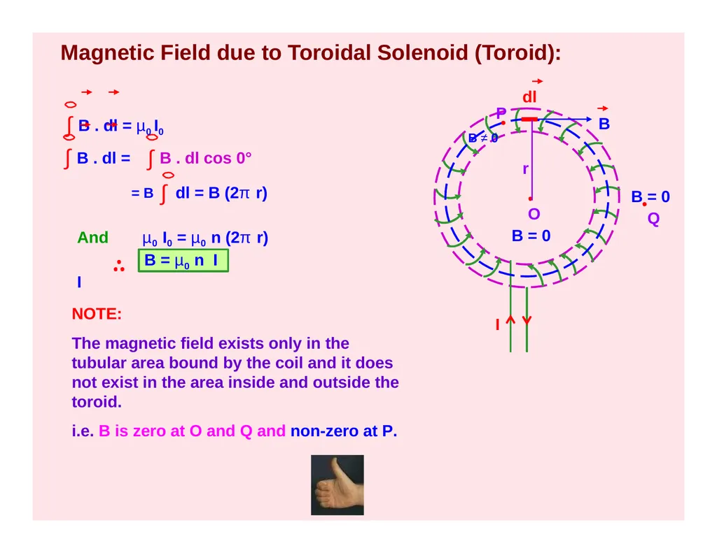
slide34. Magnetic Field due to Toroidal Solenoid (Toroid): I dl B O B = 0 B = 0 Q P
B ≠ 0 ∫ B . dl = µ0 I0 ∫ B . dl cos 0° = B ∫ dl = B (2π r) And µ0 I0 = µ0 n (2π r) I r B = µ0 n I ∫ B . dl = NOTE:
The magnetic field exists only in the tubular area bound by the coil and it does not exist in the area inside and outside the toroid.
i.e. B is zero at O and Q and non-zero at P.<br>