04
Textbook Coverage This material is introduced in different ways in different textbooks. Approximately this same material is covered in the Nilsson and Riedel textbook in the following sections:
Electric Circuits 10th Ed. by Nilsson and Riedel: Section 4.12<br>
05
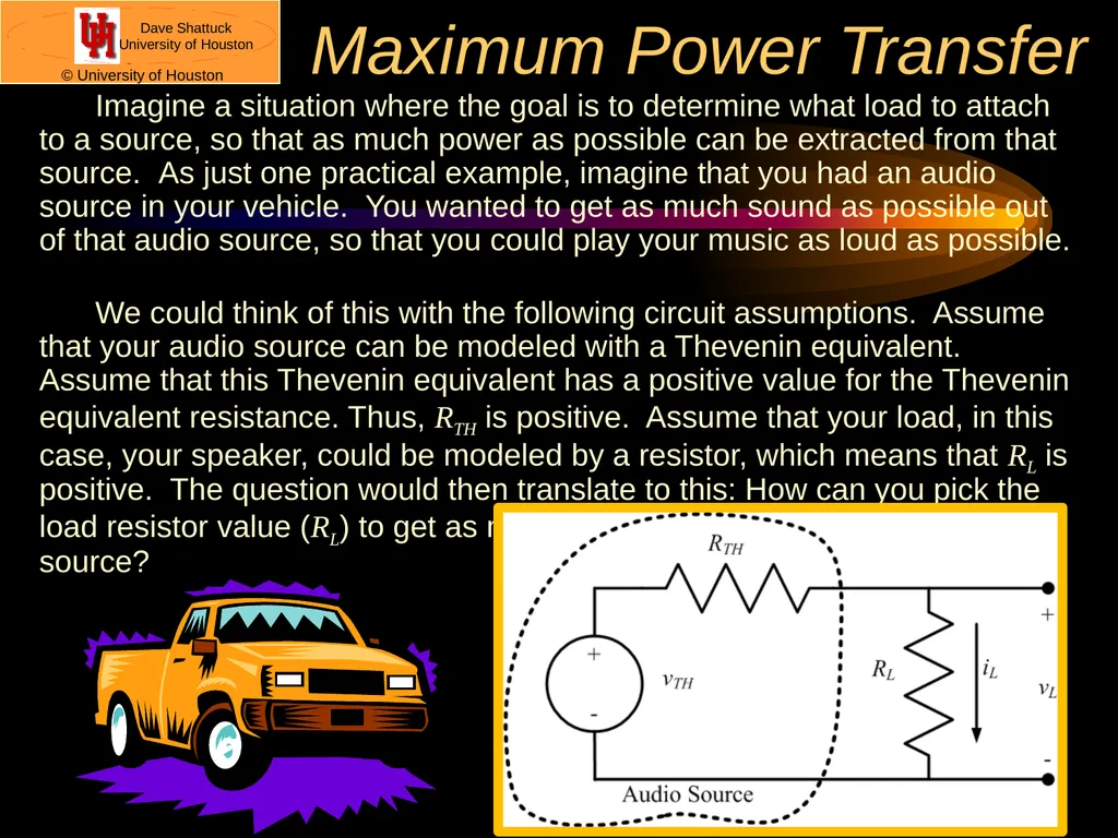
Maximum Power Transfer Imagine a situation where the goal is to determine what load to attach to a source, so that as much power as possible can be extracted from that source. As just one practical example, imagine that you had an audio source in your vehicle. You wanted to get as much sound as possible out of that audio source, so that you could play your music as loud as possible.
We could think of this with the following circuit assumptions. Assume that your audio source can be modeled with a Thevenin equivalent. Assume that this Thevenin equivalent has a positive value for the Thevenin equivalent resistance. Thus, RTH is positive. Assume that your load, in this case, your speaker, could be modeled by a resistor, which means that RL is positive. The question would then translate to this: How can you pick the load resistor value (RL) to get as much power as possible out of the audio source?<br>
06
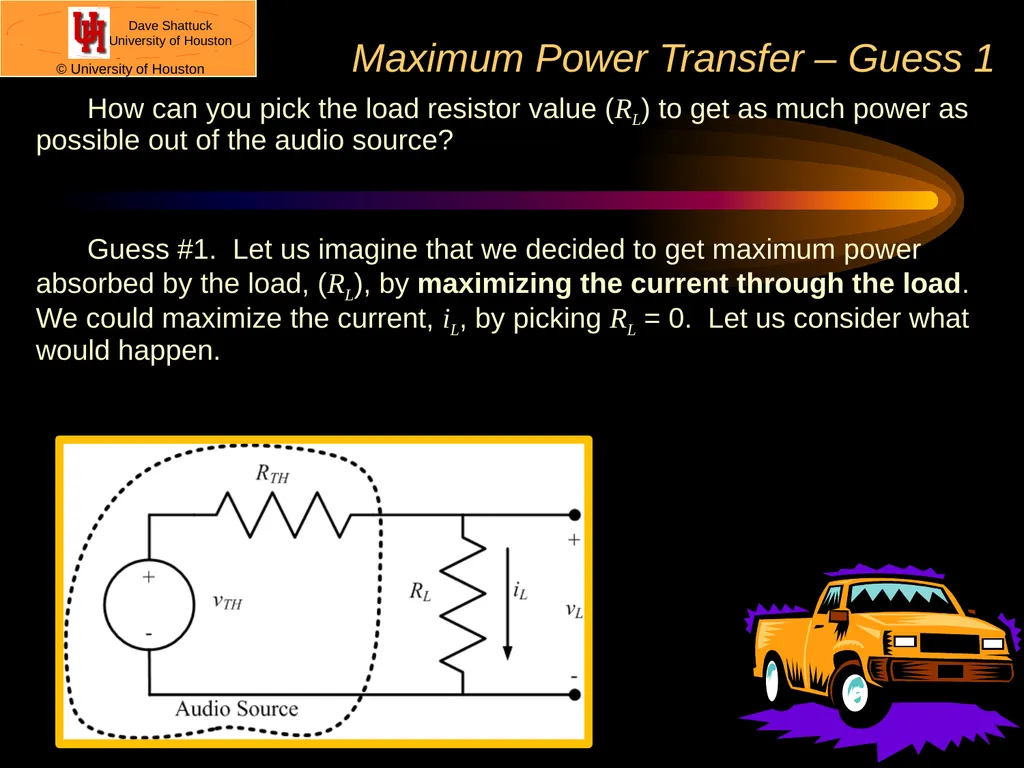
Maximum Power Transfer – Guess 1 How can you pick the load resistor value (RL) to get as much power as possible out of the audio source?
Guess #1. Let us imagine that we decided to get maximum power absorbed by the load, (RL), by maximizing the current through the load. We could maximize the current, iL, by picking RL = 0. Let us consider what would happen.<br>
07
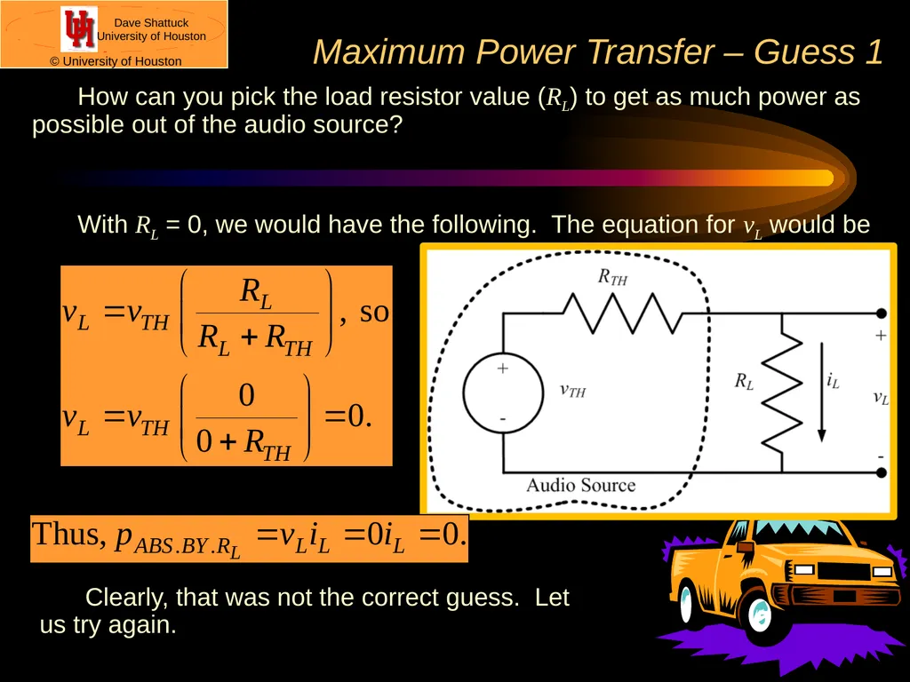
How can you pick the load resistor value (RL) to get as much power as possible out of the audio source?
With RL = 0, we would have the following. The equation for vL would be Maximum Power Transfer – Guess 1 Clearly, that was not the correct guess. Let us try again.<br>
08
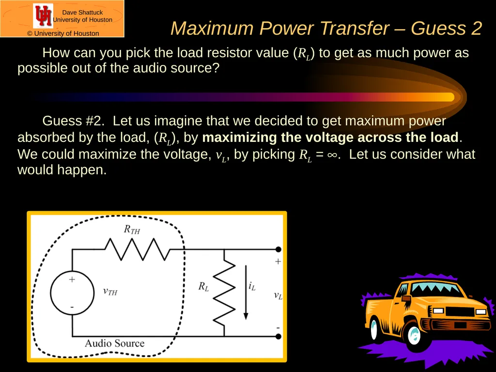
Maximum Power Transfer – Guess 2 How can you pick the load resistor value (RL) to get as much power as possible out of the audio source?
Guess #2. Let us imagine that we decided to get maximum power absorbed by the load, (RL), by maximizing the voltage across the load. We could maximize the voltage, vL, by picking RL = ¥. Let us consider what would happen.<br>
09
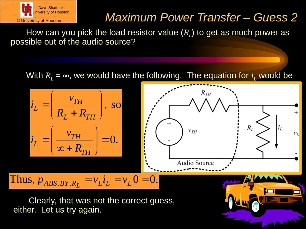
How can you pick the load resistor value (RL) to get as much power as possible out of the audio source?
With RL = ¥, we would have the following. The equation for iL would be Maximum Power Transfer – Guess 2 Clearly, that was not the correct guess, either. Let us try again.<br>
10
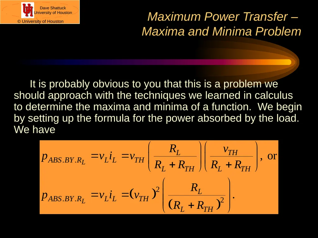
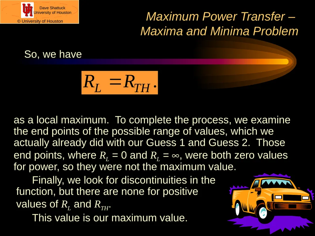
Maximum Power Transfer – �Maxima and Minima Problem It is probably obvious to you that this is a problem we should approach with the techniques we learned in calculus to determine the maxima and minima of a function. We begin by setting up the formula for the power absorbed by the load. We have<br>
11
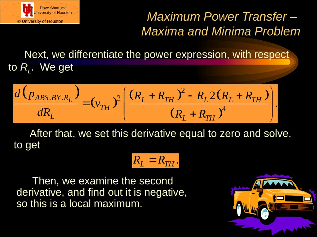
Maximum Power Transfer – �Maxima and Minima Problem Next, we differentiate the power expression, with respect to RL. We get After that, we set this derivative equal to zero and solve, to get Then, we examine the second �derivative, and find out it is negative, �so this is a local maximum.<br>
12
Maximum Power Transfer – �Maxima and Minima Problem So, we have as a local maximum. To complete the process, we examine the end points of the possible range of values, which we actually already did with our Guess 1 and Guess 2. Those end points, where RL = 0 and RL = ¥, were both zero values for power, so they were not the maximum value. Finally, we look for discontinuities in the �function, but there are none for positive �values of RL and RTH.
This value is our maximum value.<br>
13
Notes We found that the maximum power is extracted from the source, when the load resistance is equal to the Thevenin resistance of the source.
So the answer is that we should pick the resistance of the speaker in our vehicle to be equal to the Thevenin resistance of our audio source, to get the maximum power out of that audio source.
However, this conclusion is generally valid, and therefore significantly valuable. We call the rule stated in note 1 as the Maximum Power Transfer rule.
This will be useful in a wide range of applications.<br>
14
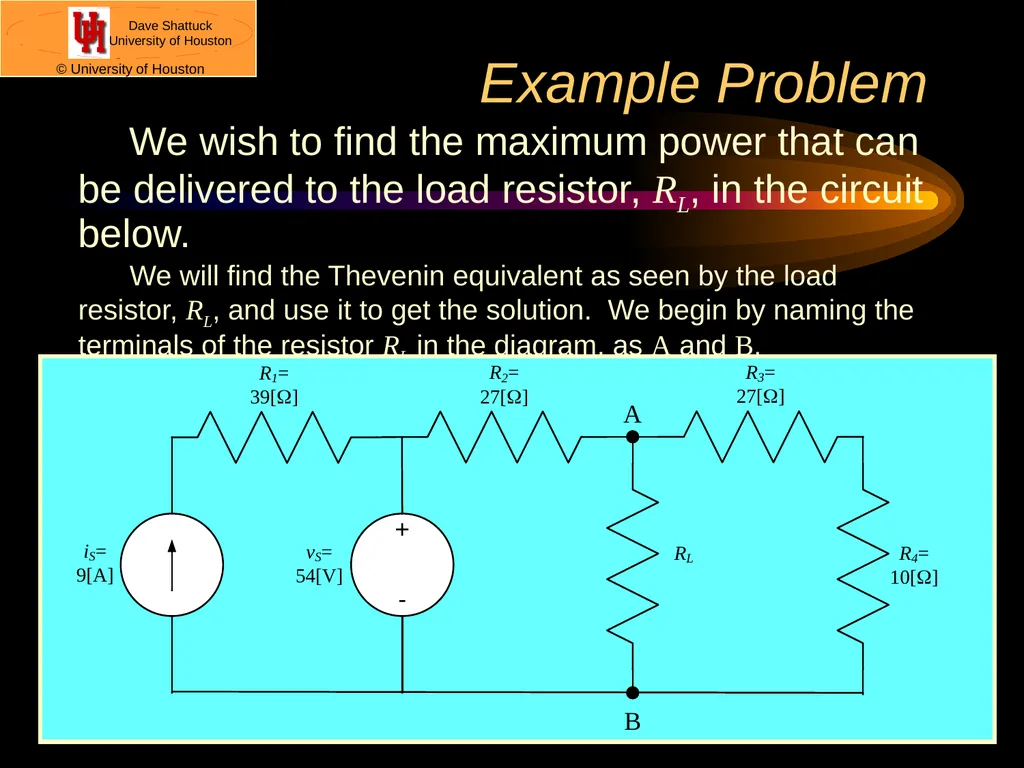
Example Problem We wish to find the maximum power that can be delivered to the load resistor, RL, in the circuit below.
We will find the Thevenin equivalent as seen by the load resistor, RL, and use it to get the solution. We begin by naming the terminals of the resistor RL in the diagram, as A and B.<br>
15
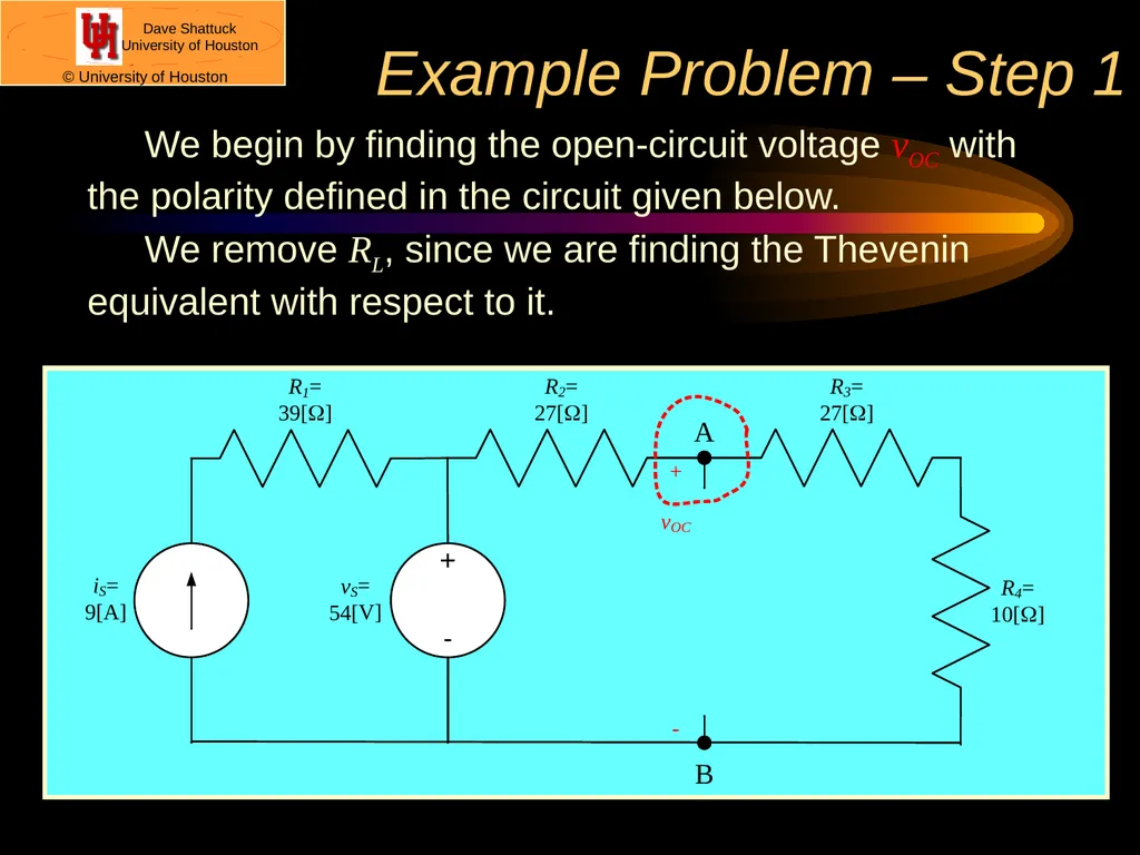
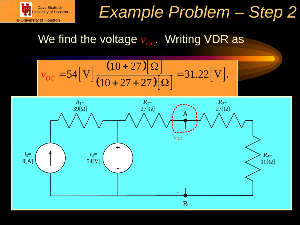
Example Problem – Step 1 We begin by finding the open-circuit voltage vOC with the polarity defined in the circuit given below.
We remove RL, since we are finding the Thevenin equivalent with respect to it.<br>
16
Example Problem – Step 2 We find the voltage vOC. Writing VDR as<br>
17
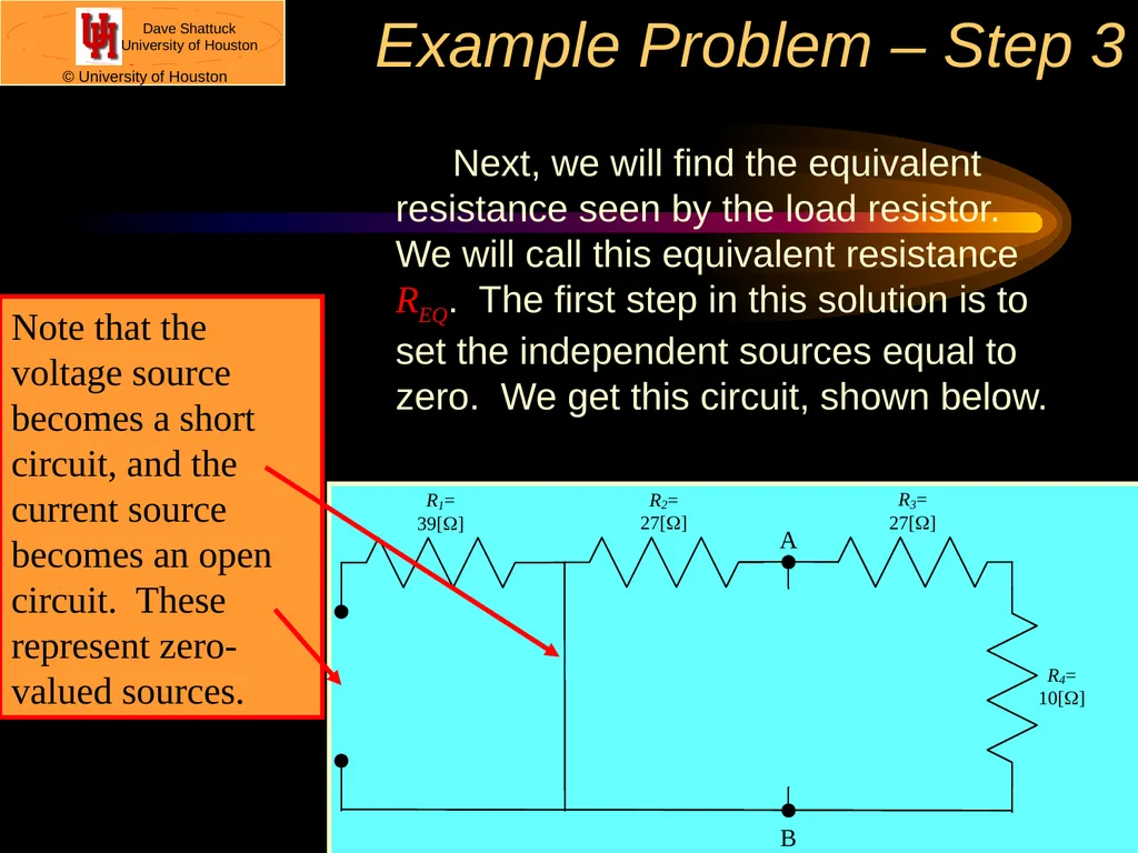
Example Problem – Step 3 Next, we will find the equivalent resistance seen by the load resistor. We will call this equivalent resistance REQ. The first step in this solution is to set the independent sources equal to zero. We get this circuit, shown below.<br>
18
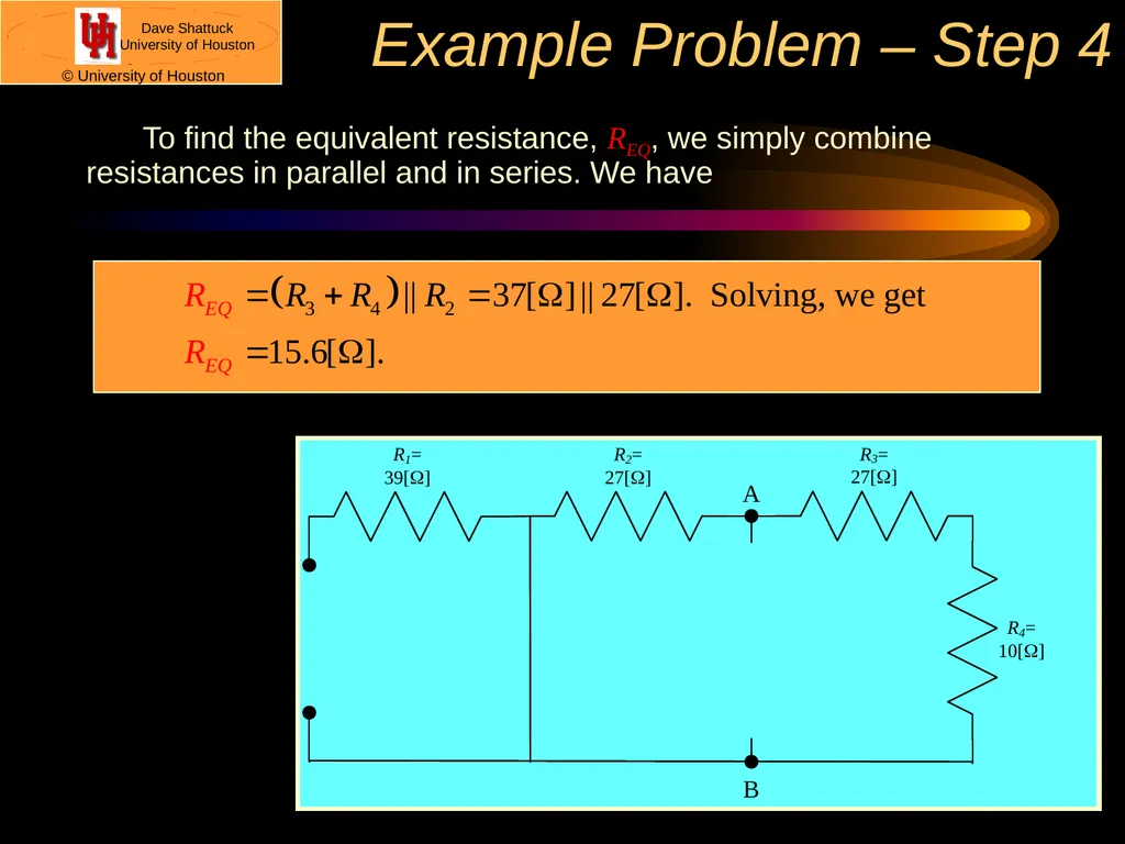
Example Problem – Step 4 To find the equivalent resistance, REQ, we simply combine resistances in parallel and in series. We have<br>
19
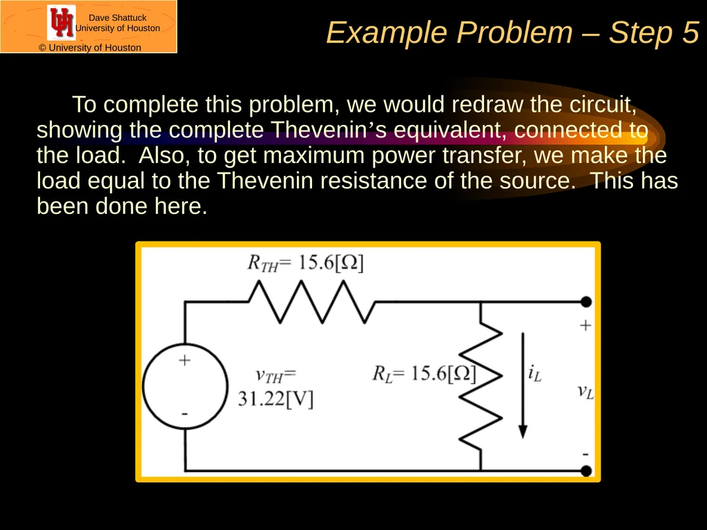
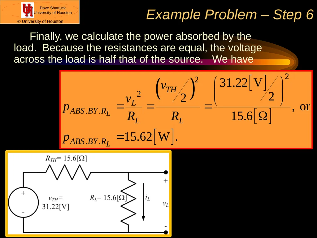
Example Problem – Step 5 To complete this problem, we would redraw the circuit, showing the complete Thevenin’s equivalent, connected to the load. Also, to get maximum power transfer, we make the load equal to the Thevenin resistance of the source. This has been done here.<br>
20
Example Problem – Step 6 Finally, we calculate the power absorbed by the load. Because the resistances are equal, the voltage across the load is half that of the source. We have<br>
21
What is the deal here?�Is this worth all this trouble? This is a good question. Yes, maximum power transfer is a very useful concept. Aside from the issue of getting as much power as possible from a source, there is the issue of reducing the effects from noise sources, which are always present in real world applications. By getting the signal power as large as possible, we increase the ratio of the signal to the noise, which is very helpful. So, yes, this concept is very much worth knowing.<br>