
EE 455 Introduction to Energy Distribution Systems
TF
Published · 48 slides · 0 views
1 / 1

Description
EE 455 Introduction to Energy Distribution Systems Introduction to Power Distribution Systems Dr. Zhaoyu Wang Department of Electrical and Computer Engineering Iowa State University wzyiastate.edu Acknowledgement: The slides are developed
Related Topics
Share
Embed code
Download this presentation From Below
"EE 455 Introduction to Energy Distribution Systems" is the property of its rightful owner. Permission is granted to download and print the materials on this website for personal, non-commercial use only, and to display it on your personal computer provided you do not modify the materials and that you retain all copyright notices contained in the materials. By downloading content from our website, you accept the terms of this agreement.
Presentation Transcript
01
EE 455 Introduction to Energy Distribution Systems Introduction to Power Distribution Systems Dr. Zhaoyu Wang
Department of Electrical and Computer Engineering
Iowa State University
wzy@iastate.edu<br>
Department of Electrical and Computer Engineering
Iowa State University
wzy@iastate.edu<br>
02
Acknowledgement: The slides are developed based in part on Distribution System Modeling and Analysis, 4th edition, William H. Kersting, CRC Press, 2017 and Electric Power Distribution Handbook, 2nd edition, T. A. Short, CRC Press, 2014. 2<br>
03
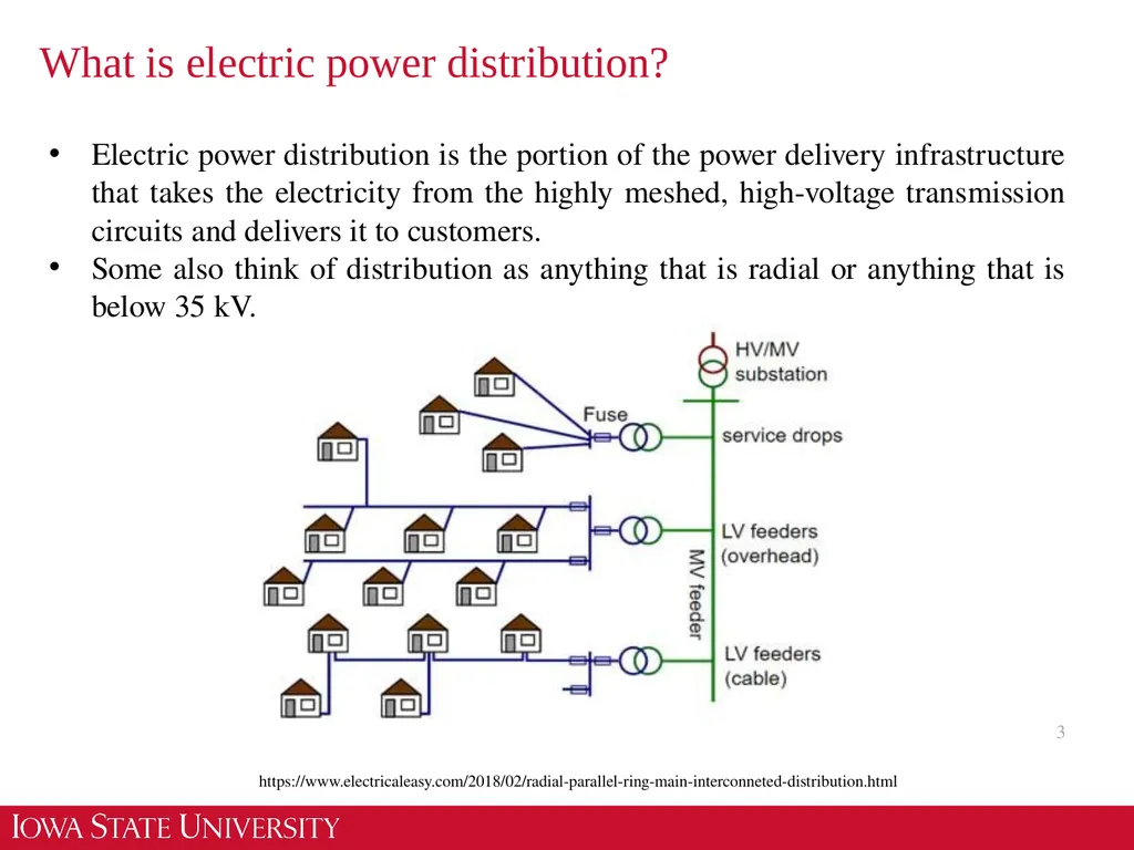
What is electric power distribution? 3 Electric power distribution is the portion of the power delivery infrastructure that takes the electricity from the highly meshed, high-voltage transmission circuits and delivers it to customers.
Some also think of distribution as anything that is radial or anything that is below 35 kV. https://www.electricaleasy.com/2018/02/radial-parallel-ring-main-interconneted-distribution.html<br>
Some also think of distribution as anything that is radial or anything that is below 35 kV. https://www.electricaleasy.com/2018/02/radial-parallel-ring-main-interconneted-distribution.html<br>
04
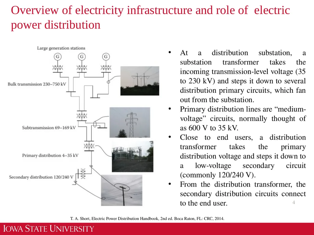
Overview of electricity infrastructure and role of electric power distribution 4 At a distribution substation, a substation transformer takes the incoming transmission-level voltage (35 to 230 kV) and steps it down to several distribution primary circuits, which fan out from the substation.
Primary distribution lines are “medium-voltage” circuits, normally thought of as 600 V to 35 kV.
Close to end users, a distribution transformer takes the primary distribution voltage and steps it down to a low-voltage secondary circuit (commonly 120/240 V).
From the distribution transformer, the secondary distribution circuits connect to the end user. T. A. Short, Electric Power Distribution Handbook, 2nd ed. Boca Raton, FL: CRC, 2014.<br>
05
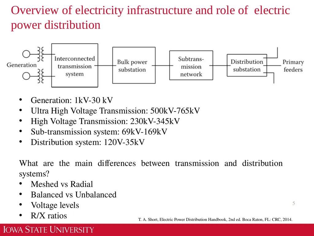
Overview of electricity infrastructure and role of electric power distribution 5 Generation: 1kV-30 kV
Ultra High Voltage Transmission: 500kV-765kV
High Voltage Transmission: 230kV-345kV
Sub-transmission system: 69kV-169kV
Distribution system: 120V-35kV
What are the main differences between transmission and distribution systems?
Meshed vs Radial
Balanced vs Unbalanced
Voltage levels
R/X ratios T. A. Short, Electric Power Distribution Handbook, 2nd ed. Boca Raton, FL: CRC, 2014.<br>
06
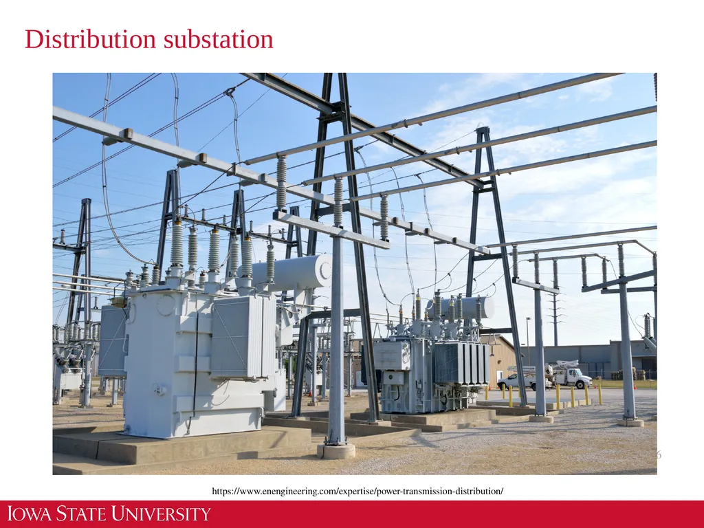
Distribution substation 6 https://www.enengineering.com/expertise/power-transmission-distribution/<br>
07
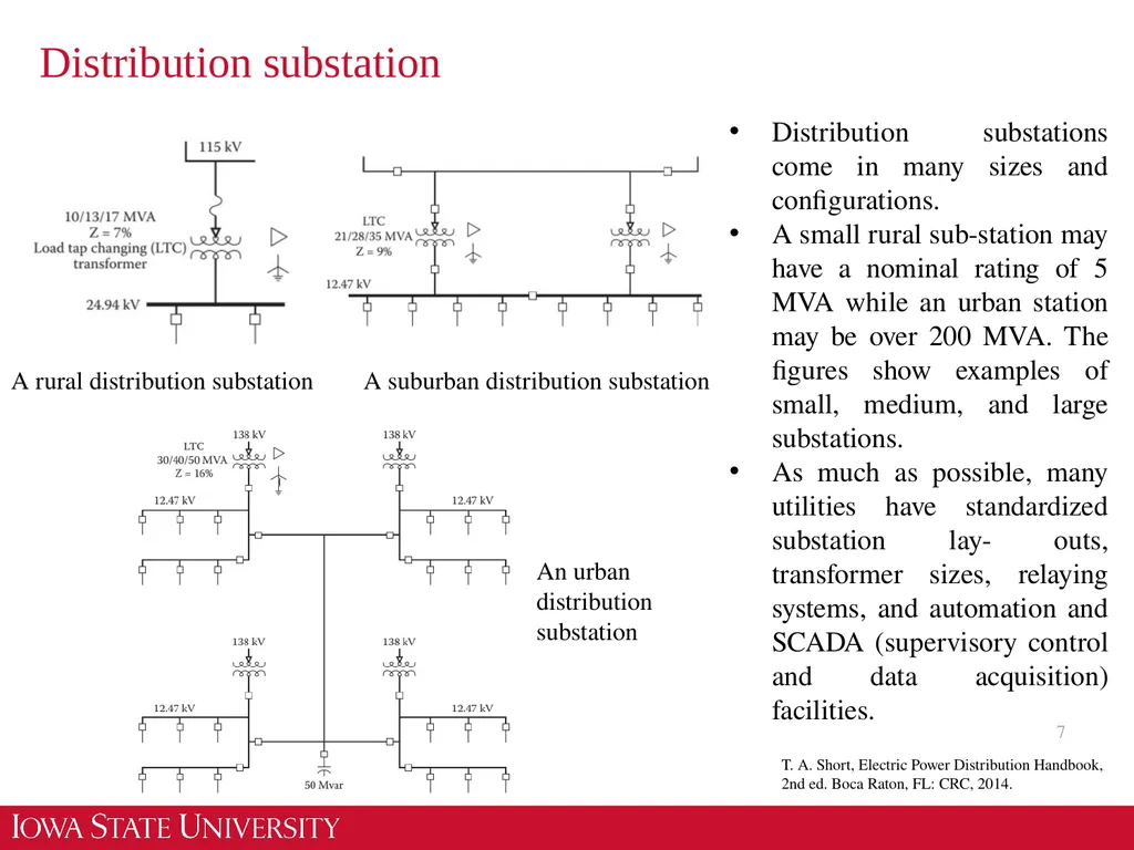
Distribution substation 7 Distribution substations come in many sizes and configurations.
A small rural sub-station may have a nominal rating of 5 MVA while an urban station may be over 200 MVA. The figures show examples of small, medium, and large substations.
As much as possible, many utilities have standardized substation lay- outs, transformer sizes, relaying systems, and automation and SCADA (supervisory control and data acquisition) facilities. A rural distribution substation A suburban distribution substation An urban distribution substation T. A. Short, Electric Power Distribution Handbook, 2nd ed. Boca Raton, FL: CRC, 2014.<br>
08
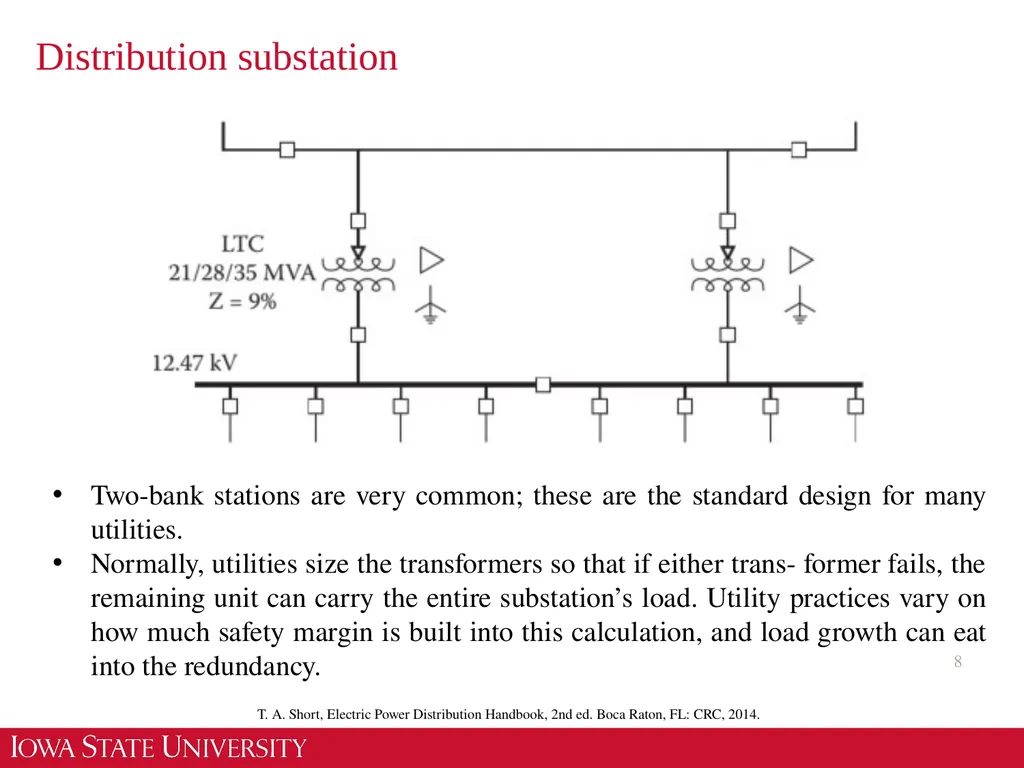
Distribution substation 8 Two-bank stations are very common; these are the standard design for many utilities.
Normally, utilities size the transformers so that if either trans- former fails, the remaining unit can carry the entire substation’s load. Utility practices vary on how much safety margin is built into this calculation, and load growth can eat into the redundancy. T. A. Short, Electric Power Distribution Handbook, 2nd ed. Boca Raton, FL: CRC, 2014.<br>
Normally, utilities size the transformers so that if either trans- former fails, the remaining unit can carry the entire substation’s load. Utility practices vary on how much safety margin is built into this calculation, and load growth can eat into the redundancy. T. A. Short, Electric Power Distribution Handbook, 2nd ed. Boca Raton, FL: CRC, 2014.<br>
09
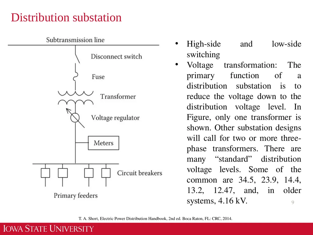
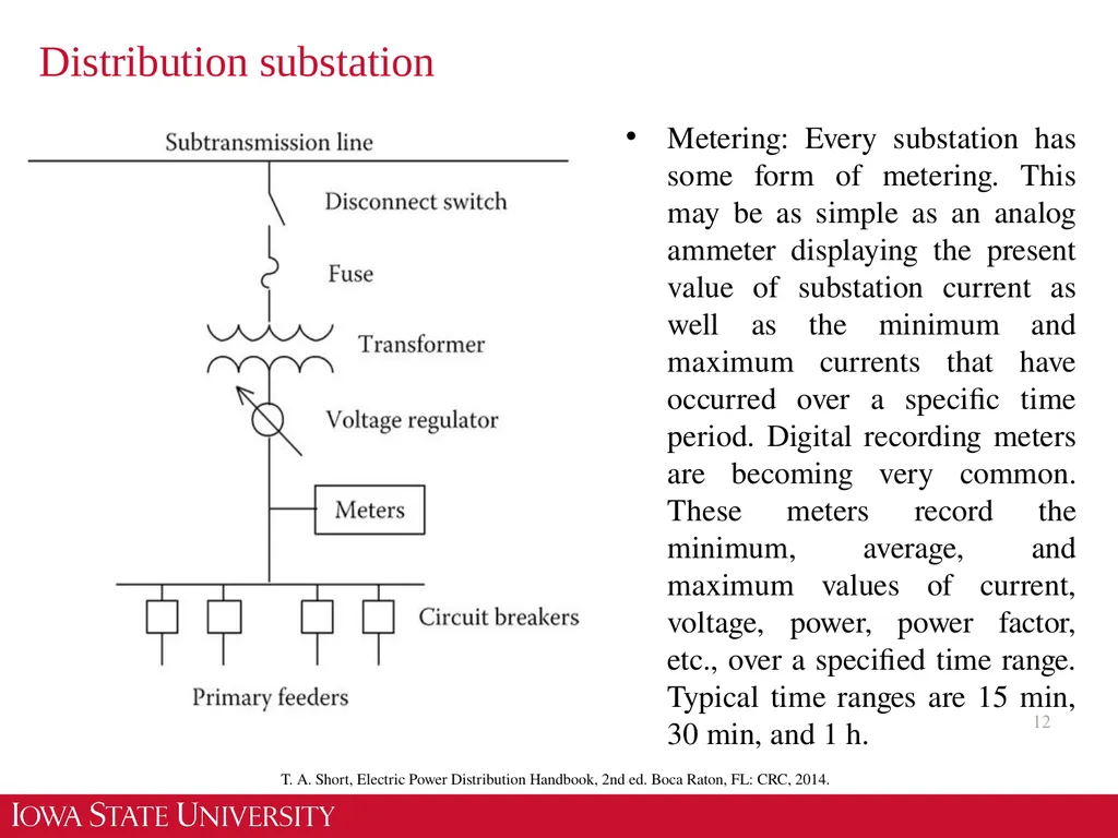
Distribution substation 9 High-side and low-side switching
Voltage transformation: The primary function of a distribution substation is to reduce the voltage down to the distribution voltage level. In Figure, only one transformer is shown. Other substation designs will call for two or more three-phase transformers. There are many “standard” distribution voltage levels. Some of the common are 34.5, 23.9, 14.4, 13.2, 12.47, and, in older systems, 4.16 kV. T. A. Short, Electric Power Distribution Handbook, 2nd ed. Boca Raton, FL: CRC, 2014.<br>
Voltage transformation: The primary function of a distribution substation is to reduce the voltage down to the distribution voltage level. In Figure, only one transformer is shown. Other substation designs will call for two or more three-phase transformers. There are many “standard” distribution voltage levels. Some of the common are 34.5, 23.9, 14.4, 13.2, 12.47, and, in older systems, 4.16 kV. T. A. Short, Electric Power Distribution Handbook, 2nd ed. Boca Raton, FL: CRC, 2014.<br>
10
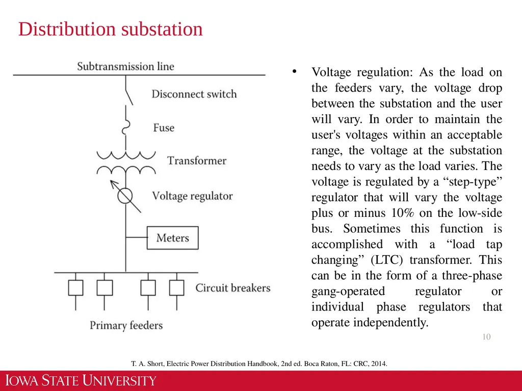
Distribution substation 10 Voltage regulation: As the load on the feeders vary, the voltage drop between the substation and the user will vary. In order to maintain the user's voltages within an acceptable range, the voltage at the substation needs to vary as the load varies. The voltage is regulated by a “step-type” regulator that will vary the voltage plus or minus 10% on the low-side bus. Sometimes this function is accomplished with a “load tap changing” (LTC) transformer. This can be in the form of a three-phase gang-operated regulator or individual phase regulators that operate independently. T. A. Short, Electric Power Distribution Handbook, 2nd ed. Boca Raton, FL: CRC, 2014.<br>
11
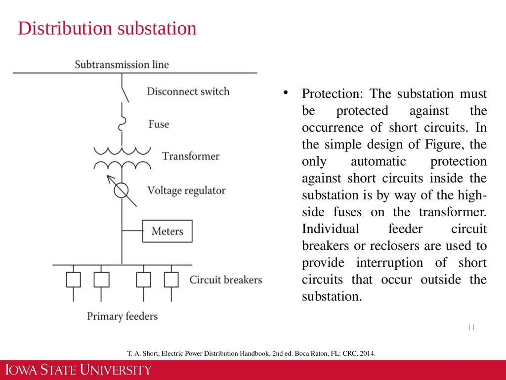
Distribution substation 11 Protection: The substation must be protected against the occurrence of short circuits. In the simple design of Figure, the only automatic protection against short circuits inside the substation is by way of the high-side fuses on the transformer. Individual feeder circuit breakers or reclosers are used to provide interruption of short circuits that occur outside the substation. T. A. Short, Electric Power Distribution Handbook, 2nd ed. Boca Raton, FL: CRC, 2014.<br>
12
Distribution substation 12 Metering: Every substation has some form of metering. This may be as simple as an analog ammeter displaying the present value of substation current as well as the minimum and maximum currents that have occurred over a specific time period. Digital recording meters are becoming very common. These meters record the minimum, average, and maximum values of current, voltage, power, power factor, etc., over a specified time range. Typical time ranges are 15 min, 30 min, and 1 h. T. A. Short, Electric Power Distribution Handbook, 2nd ed. Boca Raton, FL: CRC, 2014.<br>
13
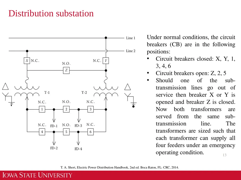
Distribution substation 13 Under normal conditions, the circuit breakers (CB) are in the following positions:
Circuit breakers closed: X, Y, 1, 3, 4, 6
Circuit breakers open: Z, 2, 5
Should one of the sub-transmission lines go out of service then breaker X or Y is opened and breaker Z is closed. Now both transformers are served from the same sub-transmission line. The transformers are sized such that each transformer can supply all four feeders under an emergency operating condition. T. A. Short, Electric Power Distribution Handbook, 2nd ed. Boca Raton, FL: CRC, 2014.<br>
14
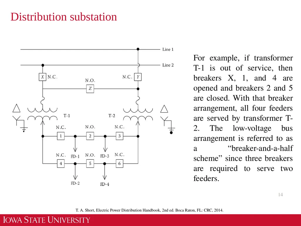
Distribution substation 14 For example, if transformer T-1 is out of service, then breakers X, 1, and 4 are opened and breakers 2 and 5 are closed. With that breaker arrangement, all four feeders are served by transformer T-2. The low-voltage bus arrangement is referred to as a “breaker-and-a-half scheme” since three breakers are required to serve two feeders. T. A. Short, Electric Power Distribution Handbook, 2nd ed. Boca Raton, FL: CRC, 2014.<br>
15
Distribution substation 15 Consider a typical substation that might be fed by two incoming 138 kV lines feeding two 32 MVA, 138/12.47 kV transformers, each with a low-voltage bus. Each bus has four outgoing distribution feeders of 9 MVA peak capacity each. The total site cost of the substation is $600,000. The total transmission cost including high-side bus circuit breakers is estimated to be $900,000. The total costs of the two transformers and associated equipment is $1,100,000. The feeder bus-work/getaway cost is $400,000.
The total cost of this substation=$600,000+$900,000+$1,100,000+$400,000=$3,000,000<br>
The total cost of this substation=$600,000+$900,000+$1,100,000+$400,000=$3,000,000<br>
16
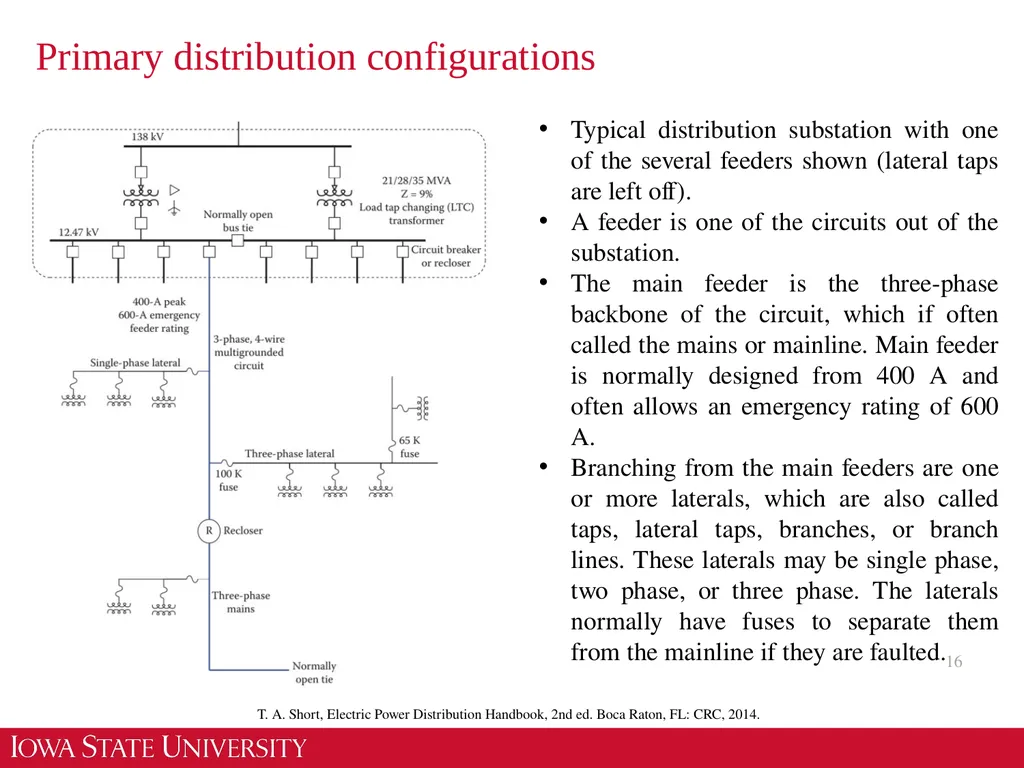
Primary distribution configurations 16 Typical distribution substation with one of the several feeders shown (lateral taps are left off).
A feeder is one of the circuits out of the substation.
The main feeder is the three-phase backbone of the circuit, which if often called the mains or mainline. Main feeder is normally designed from 400 A and often allows an emergency rating of 600 A.
Branching from the main feeders are one or more laterals, which are also called taps, lateral taps, branches, or branch lines. These laterals may be single phase, two phase, or three phase. The laterals normally have fuses to separate them from the mainline if they are faulted. T. A. Short, Electric Power Distribution Handbook, 2nd ed. Boca Raton, FL: CRC, 2014.<br>
17
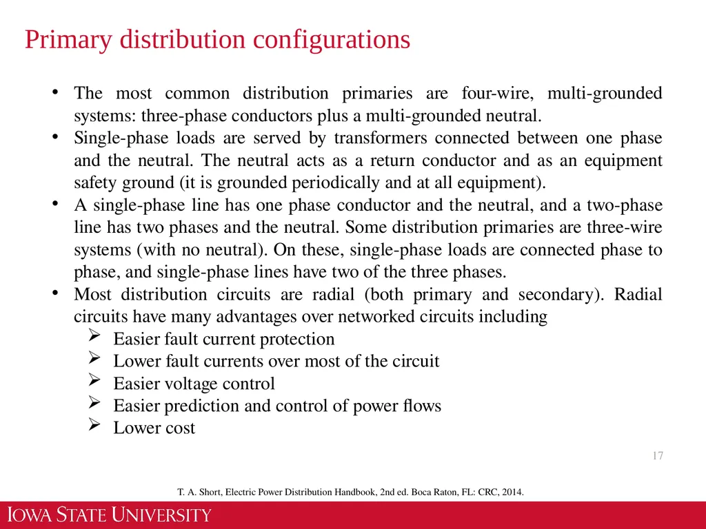
Primary distribution configurations 17 The most common distribution primaries are four-wire, multi-grounded systems: three-phase conductors plus a multi-grounded neutral.
Single-phase loads are served by transformers connected between one phase and the neutral. The neutral acts as a return conductor and as an equipment safety ground (it is grounded periodically and at all equipment).
A single-phase line has one phase conductor and the neutral, and a two-phase line has two phases and the neutral. Some distribution primaries are three-wire systems (with no neutral). On these, single-phase loads are connected phase to phase, and single-phase lines have two of the three phases.
Most distribution circuits are radial (both primary and secondary). Radial circuits have many advantages over networked circuits including
Easier fault current protection
Lower fault currents over most of the circuit
Easier voltage control
Easier prediction and control of power flows
Lower cost T. A. Short, Electric Power Distribution Handbook, 2nd ed. Boca Raton, FL: CRC, 2014.<br>
18
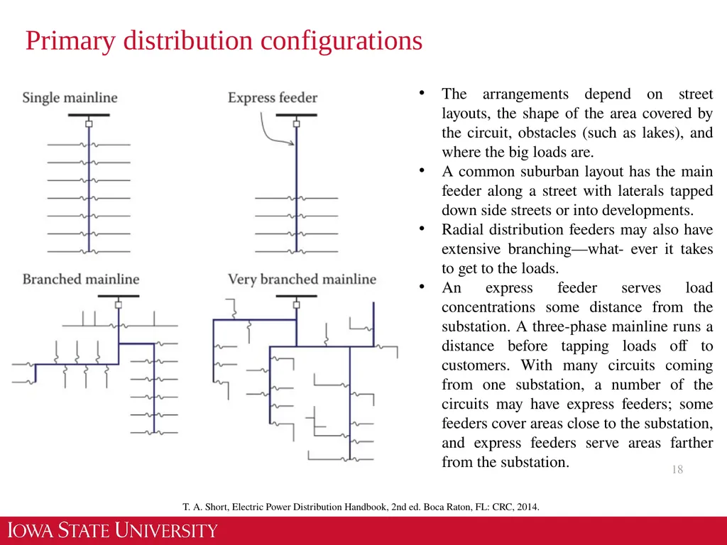
Primary distribution configurations 18 The arrangements depend on street layouts, the shape of the area covered by the circuit, obstacles (such as lakes), and where the big loads are.
A common suburban layout has the main feeder along a street with laterals tapped down side streets or into developments.
Radial distribution feeders may also have extensive branching—what- ever it takes to get to the loads.
An express feeder serves load concentrations some distance from the substation. A three-phase mainline runs a distance before tapping loads off to customers. With many circuits coming from one substation, a number of the circuits may have express feeders; some feeders cover areas close to the substation, and express feeders serve areas farther from the substation. T. A. Short, Electric Power Distribution Handbook, 2nd ed. Boca Raton, FL: CRC, 2014.<br>
19
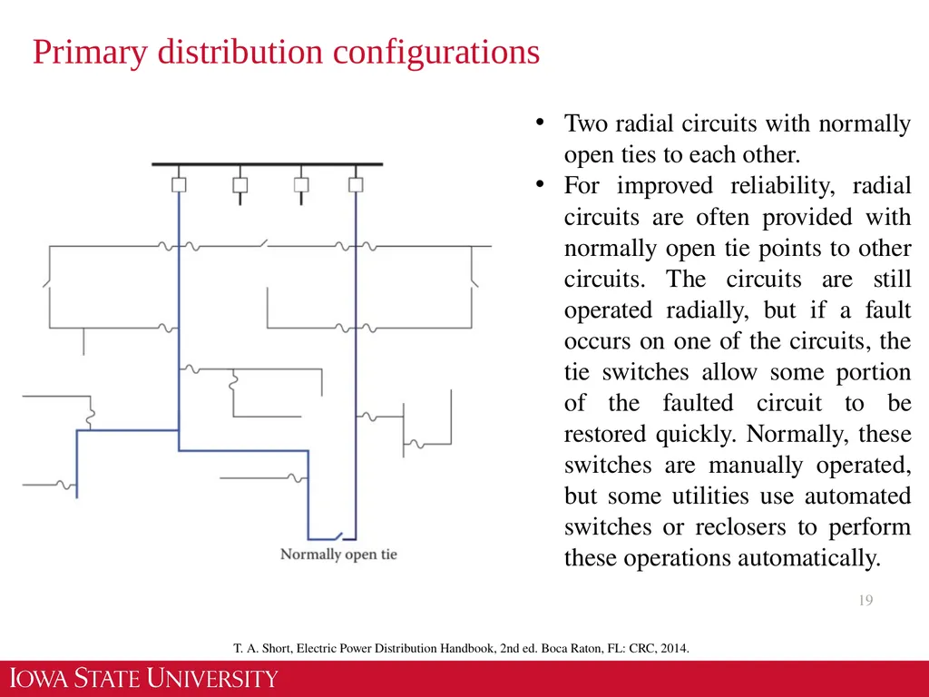
Primary distribution configurations 19 Two radial circuits with normally open ties to each other.
For improved reliability, radial circuits are often provided with normally open tie points to other circuits. The circuits are still operated radially, but if a fault occurs on one of the circuits, the tie switches allow some portion of the faulted circuit to be restored quickly. Normally, these switches are manually operated, but some utilities use automated switches or reclosers to perform these operations automatically. T. A. Short, Electric Power Distribution Handbook, 2nd ed. Boca Raton, FL: CRC, 2014.<br>
For improved reliability, radial circuits are often provided with normally open tie points to other circuits. The circuits are still operated radially, but if a fault occurs on one of the circuits, the tie switches allow some portion of the faulted circuit to be restored quickly. Normally, these switches are manually operated, but some utilities use automated switches or reclosers to perform these operations automatically. T. A. Short, Electric Power Distribution Handbook, 2nd ed. Boca Raton, FL: CRC, 2014.<br>
20
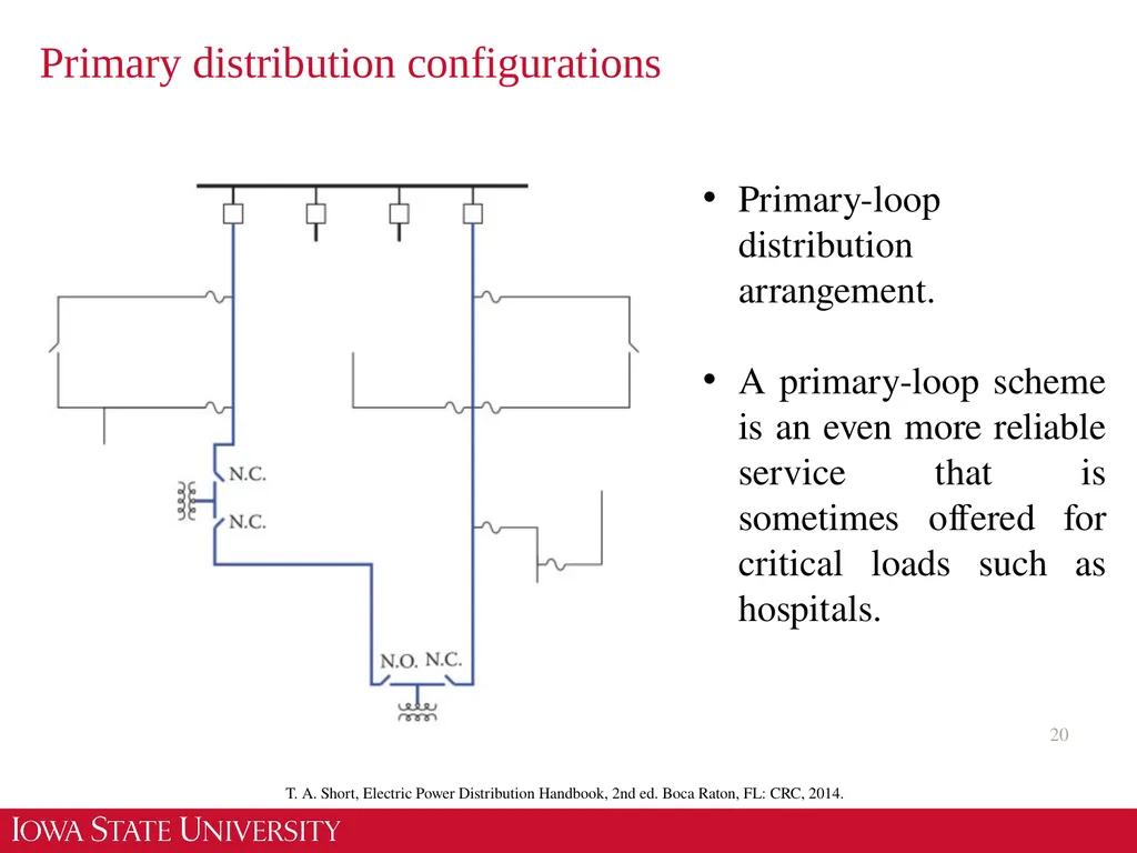
Primary distribution configurations 20 Primary-loop distribution arrangement.
A primary-loop scheme is an even more reliable service that is sometimes offered for critical loads such as hospitals. T. A. Short, Electric Power Distribution Handbook, 2nd ed. Boca Raton, FL: CRC, 2014.<br>
A primary-loop scheme is an even more reliable service that is sometimes offered for critical loads such as hospitals. T. A. Short, Electric Power Distribution Handbook, 2nd ed. Boca Raton, FL: CRC, 2014.<br>
21
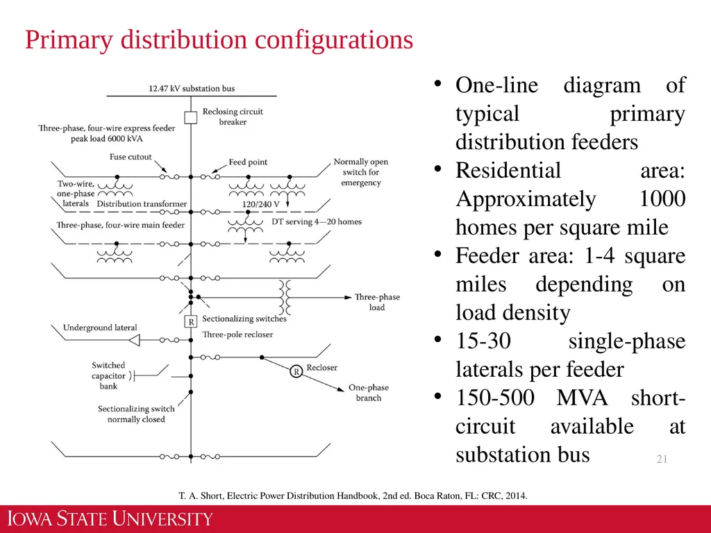
Primary distribution configurations 21 One-line diagram of typical primary distribution feeders
Residential area: Approximately 1000 homes per square mile
Feeder area: 1-4 square miles depending on load density
15-30 single-phase laterals per feeder
150-500 MVA short-circuit available at substation bus T. A. Short, Electric Power Distribution Handbook, 2nd ed. Boca Raton, FL: CRC, 2014.<br>
Residential area: Approximately 1000 homes per square mile
Feeder area: 1-4 square miles depending on load density
15-30 single-phase laterals per feeder
150-500 MVA short-circuit available at substation bus T. A. Short, Electric Power Distribution Handbook, 2nd ed. Boca Raton, FL: CRC, 2014.<br>
22
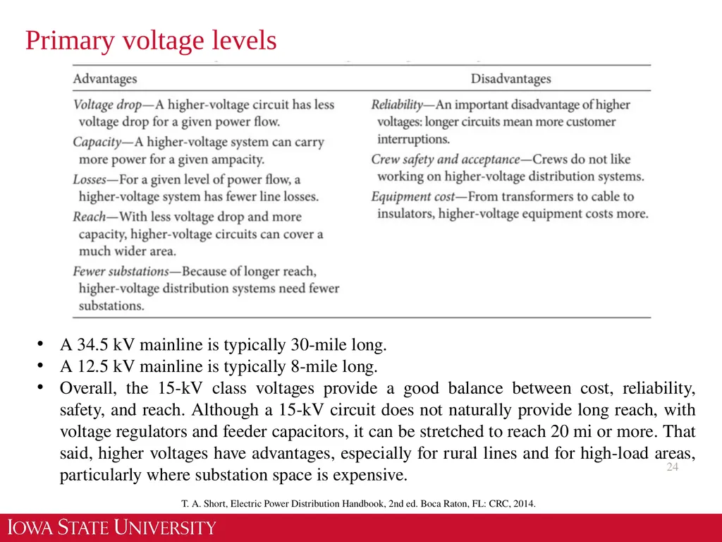
Primary voltage levels 22 Most primary distribution voltages are between 4 and 35 kV. In this class, unless otherwise specified, voltages are given as line-to-line voltages; this follows the normal industry practice.
The four major voltage classes are 5, 15, 25, and 35 kV. A voltage class is a term applied to a set of distribution voltages and the equipment common to them; it is not the actual system voltage. For example, a 15-kV insulator is suitable for application on any 15-kV class voltage, including 12.47, 13.2, and 13.8 kV.
Utilities most widely use the 15-kV voltages. The most common 15-kV voltage is 12.47 kV, which has a line-to-ground voltage of 7.2 kV.
The dividing line between distribution and sub-transmission is often gray. Some lines act as both sub-transmission and distribution circuits. A 34.5-kV circuit may feed a few 12.5-kV distribution substations, but it may also serve some load directly. Some utilities would refer to this as sub-transmission; others would refer to this as distribution.
We saw a move to higher-voltage primary distribution systems. Higher-voltage distribution systems have advantages and disadvantage. T. A. Short, Electric Power Distribution Handbook, 2nd ed. Boca Raton, FL: CRC, 2014.<br>
23
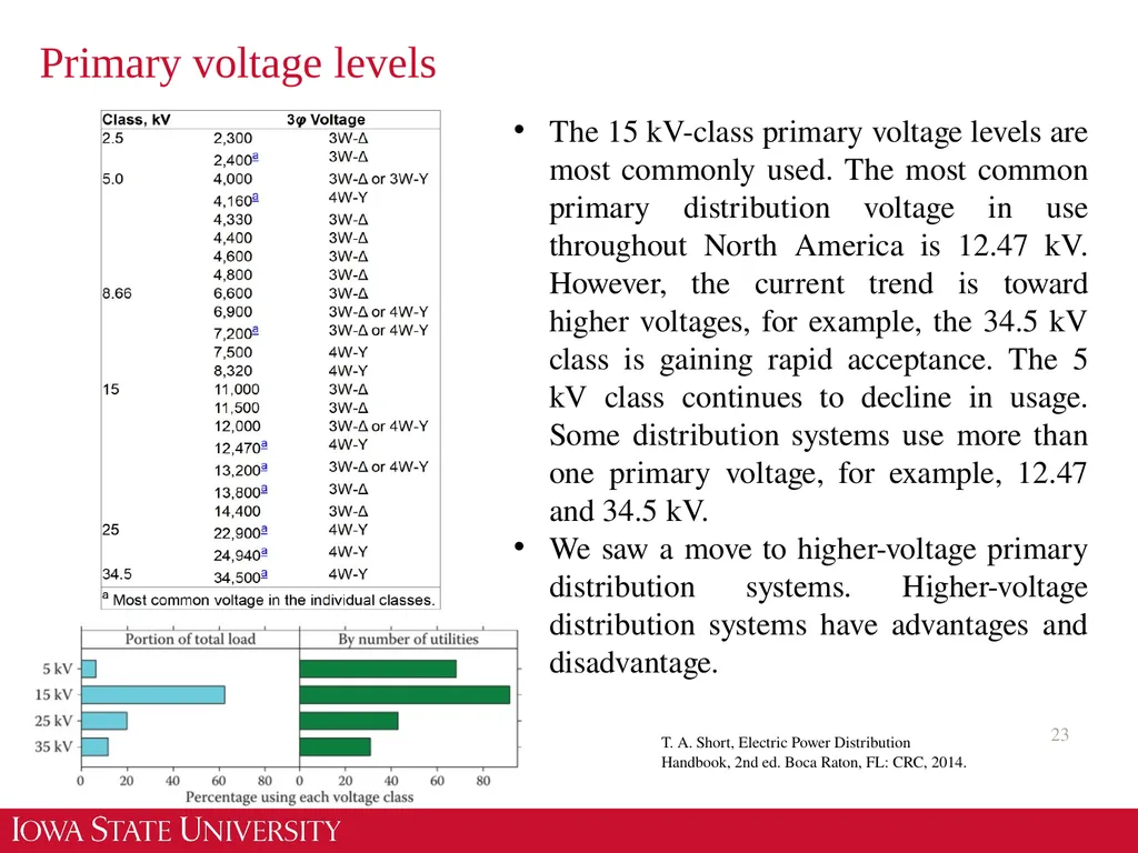
Primary voltage levels 23 The 15 kV-class primary voltage levels are most commonly used. The most common primary distribution voltage in use throughout North America is 12.47 kV. However, the current trend is toward higher voltages, for example, the 34.5 kV class is gaining rapid acceptance. The 5 kV class continues to decline in usage. Some distribution systems use more than one primary voltage, for example, 12.47 and 34.5 kV.
We saw a move to higher-voltage primary distribution systems. Higher-voltage distribution systems have advantages and disadvantage. T. A. Short, Electric Power Distribution Handbook, 2nd ed. Boca Raton, FL: CRC, 2014.<br>
We saw a move to higher-voltage primary distribution systems. Higher-voltage distribution systems have advantages and disadvantage. T. A. Short, Electric Power Distribution Handbook, 2nd ed. Boca Raton, FL: CRC, 2014.<br>
24
Primary voltage levels 24 A 34.5 kV mainline is typically 30-mile long.
A 12.5 kV mainline is typically 8-mile long.
Overall, the 15-kV class voltages provide a good balance between cost, reliability, safety, and reach. Although a 15-kV circuit does not naturally provide long reach, with voltage regulators and feeder capacitors, it can be stretched to reach 20 mi or more. That said, higher voltages have advantages, especially for rural lines and for high-load areas, particularly where substation space is expensive. T. A. Short, Electric Power Distribution Handbook, 2nd ed. Boca Raton, FL: CRC, 2014.<br>
25
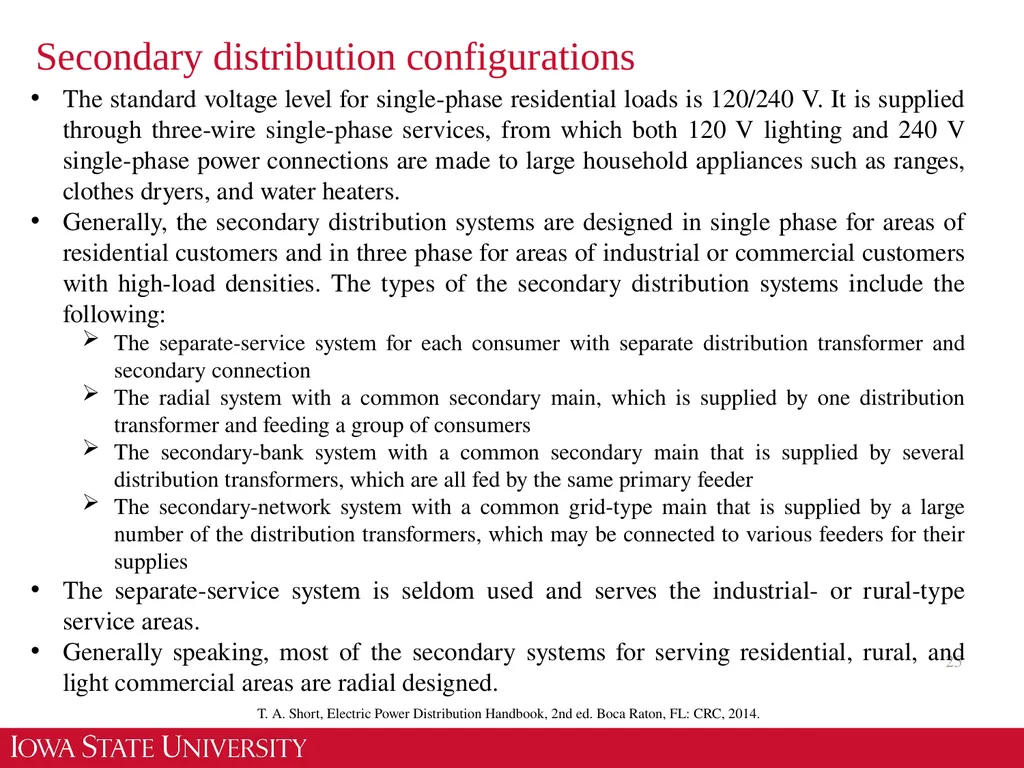
Secondary distribution configurations 25 The standard voltage level for single-phase residential loads is 120/240 V. It is supplied through three-wire single-phase services, from which both 120 V lighting and 240 V single-phase power connections are made to large household appliances such as ranges, clothes dryers, and water heaters.
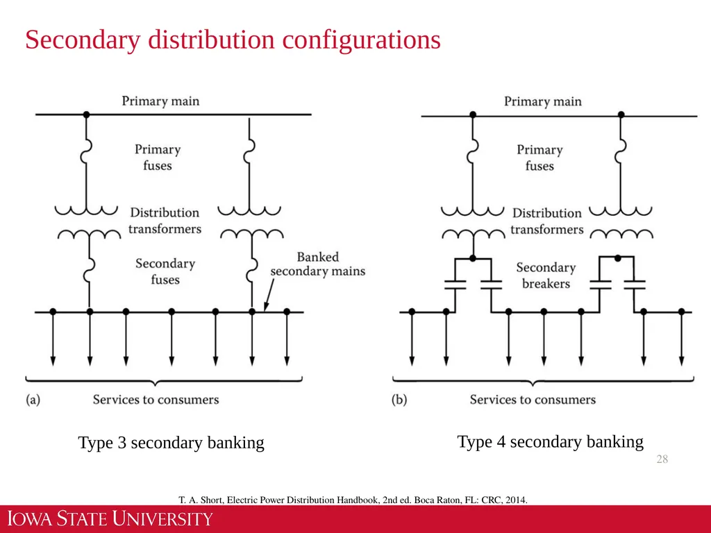
Generally, the secondary distribution systems are designed in single phase for areas of residential customers and in three phase for areas of industrial or commercial customers with high-load densities. The types of the secondary distribution systems include the following:
The separate-service system for each consumer with separate distribution transformer and secondary connection
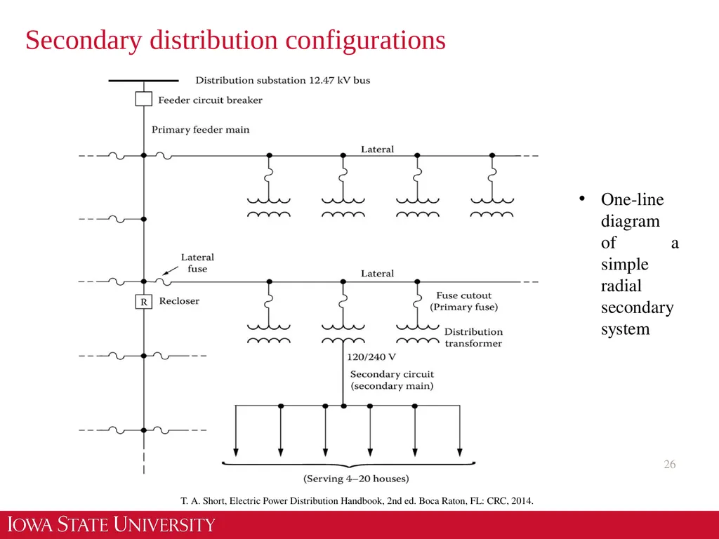
The radial system with a common secondary main, which is supplied by one distribution transformer and feeding a group of consumers
The secondary-bank system with a common secondary main that is supplied by several distribution transformers, which are all fed by the same primary feeder
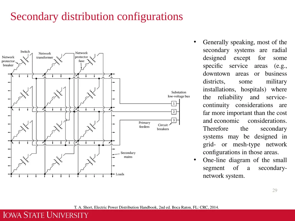
The secondary-network system with a common grid-type main that is supplied by a large number of the distribution transformers, which may be connected to various feeders for their supplies
The separate-service system is seldom used and serves the industrial- or rural-type service areas.
Generally speaking, most of the secondary systems for serving residential, rural, and light commercial areas are radial designed. T. A. Short, Electric Power Distribution Handbook, 2nd ed. Boca Raton, FL: CRC, 2014.<br>
26
Secondary distribution configurations 26 One-line diagram of a simple radial secondary system T. A. Short, Electric Power Distribution Handbook, 2nd ed. Boca Raton, FL: CRC, 2014.<br>
27
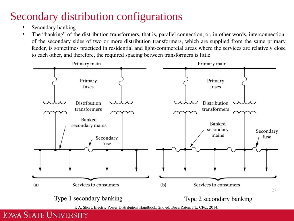
Secondary distribution configurations 27 Secondary banking
The “banking” of the distribution transformers, that is, parallel connection, or, in other words, interconnection, of the secondary sides of two or more distribution transformers, which are supplied from the same primary feeder, is sometimes practiced in residential and light-commercial areas where the services are relatively close to each other, and therefore, the required spacing between transformers is little. T. A. Short, Electric Power Distribution Handbook, 2nd ed. Boca Raton, FL: CRC, 2014. Type 1 secondary banking Type 2 secondary banking<br>
The “banking” of the distribution transformers, that is, parallel connection, or, in other words, interconnection, of the secondary sides of two or more distribution transformers, which are supplied from the same primary feeder, is sometimes practiced in residential and light-commercial areas where the services are relatively close to each other, and therefore, the required spacing between transformers is little. T. A. Short, Electric Power Distribution Handbook, 2nd ed. Boca Raton, FL: CRC, 2014. Type 1 secondary banking Type 2 secondary banking<br>
28
Secondary distribution configurations 28 T. A. Short, Electric Power Distribution Handbook, 2nd ed. Boca Raton, FL: CRC, 2014. Type 3 secondary banking Type 4 secondary banking<br>
29
Secondary distribution configurations 29 T. A. Short, Electric Power Distribution Handbook, 2nd ed. Boca Raton, FL: CRC, 2014. Generally speaking, most of the secondary systems are radial designed except for some specific service areas (e.g., downtown areas or business districts, some military installations, hospitals) where the reliability and service-continuity considerations are far more important than the cost and economic considerations. Therefore the secondary systems may be designed in grid- or mesh-type network configurations in those areas.
One-line diagram of the small segment of a secondary-network system.<br>
One-line diagram of the small segment of a secondary-network system.<br>
30
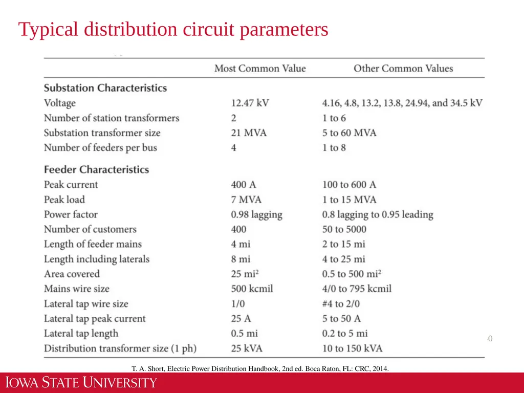
Typical distribution circuit parameters 30 T. A. Short, Electric Power Distribution Handbook, 2nd ed. Boca Raton, FL: CRC, 2014.<br>
31
Radial Feeders 31 T. A. Short, Electric Power Distribution Handbook, 2nd ed. Boca Raton, FL: CRC, 2014. Components of the feeder may consist of the following:
1. Three-phase primary “main” feeder
2. Three-phase, two-phase (“V” phase), and single-phase laterals
3. Step-type voltage regulators
4. In-line transformers
5. Shunt capacitor banks
6. Distribution transformers
7. Secondaries
8. Three-phase, two-phase, and single-phase loads The loading of a distribution feeder is inherently unbalanced because of the large number of unequal single-phase loads that must be served.
An additional unbalance is introduced by the nonequilateral conductor spacings of the three-phase overhead and underground line segments.
Conventional power-flow and short-circuit programs used for transmission system studies are not adequate.
Three-phase models of the major components must be utilized.<br>
32
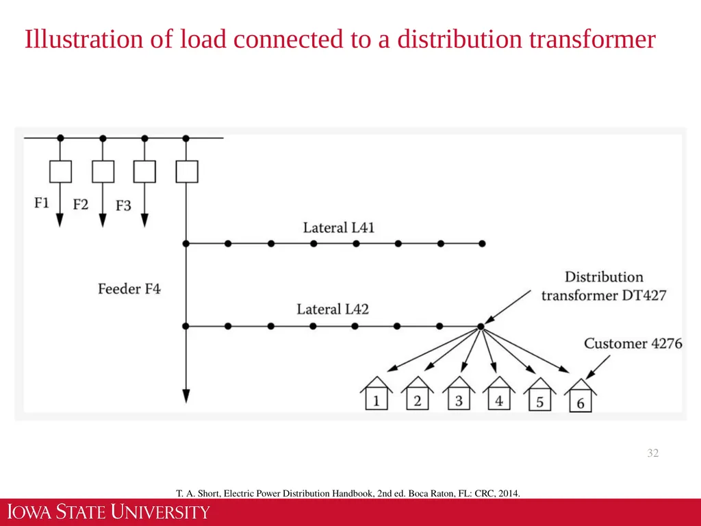
Illustration of load connected to a distribution transformer 32 T. A. Short, Electric Power Distribution Handbook, 2nd ed. Boca Raton, FL: CRC, 2014.<br>
33
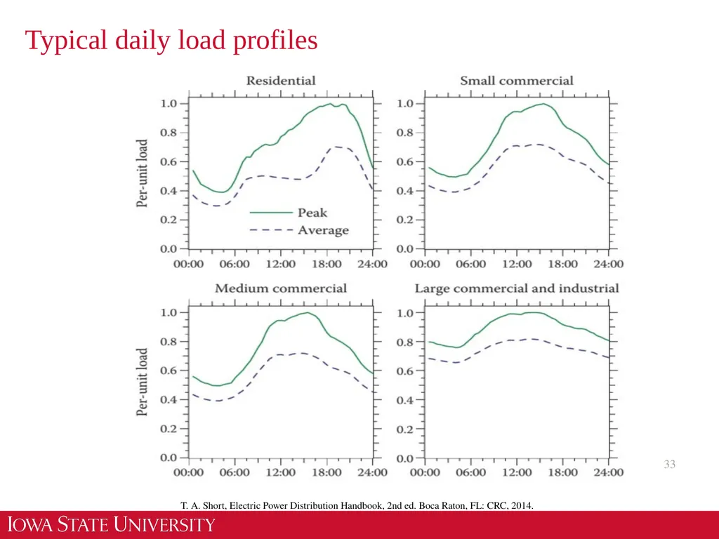
Typical daily load profiles 33 T. A. Short, Electric Power Distribution Handbook, 2nd ed. Boca Raton, FL: CRC, 2014.<br>
34
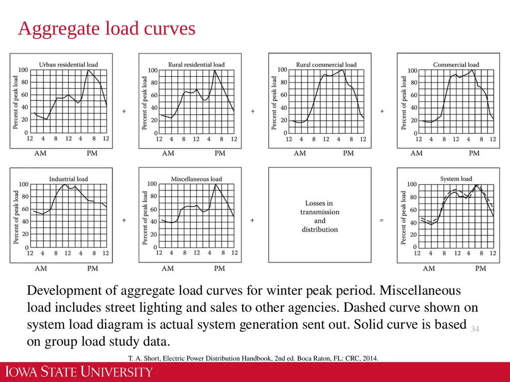
Aggregate load curves 34 T. A. Short, Electric Power Distribution Handbook, 2nd ed. Boca Raton, FL: CRC, 2014. Development of aggregate load curves for winter peak period. Miscellaneous load includes street lighting and sales to other agencies. Dashed curve shown on system load diagram is actual system generation sent out. Solid curve is based on group load study data.<br>
35
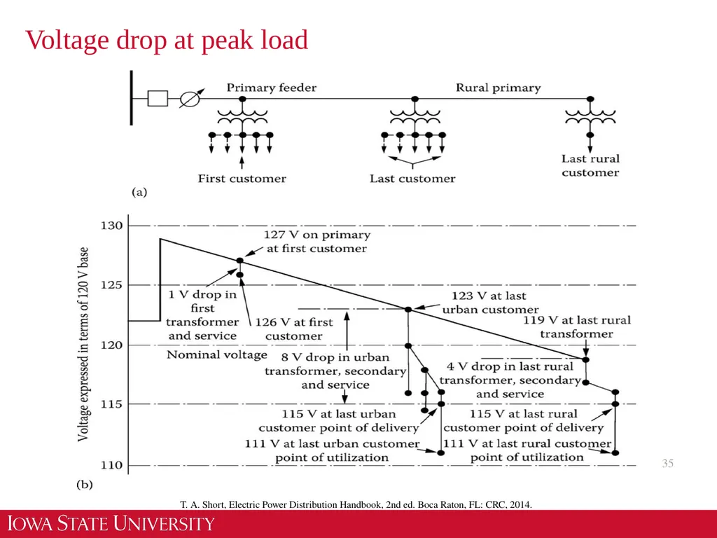
Voltage drop at peak load 35 T. A. Short, Electric Power Distribution Handbook, 2nd ed. Boca Raton, FL: CRC, 2014.<br>
36
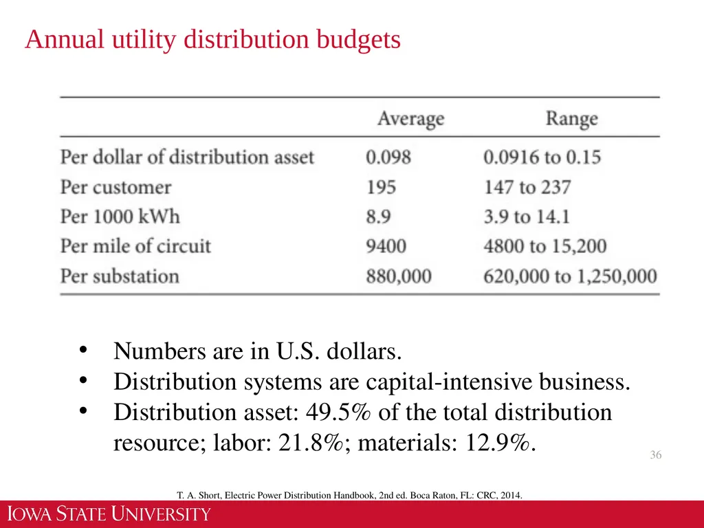
Annual utility distribution budgets 36 T. A. Short, Electric Power Distribution Handbook, 2nd ed. Boca Raton, FL: CRC, 2014. Numbers are in U.S. dollars.
Distribution systems are capital-intensive business.
Distribution asset: 49.5% of the total distribution resource; labor: 21.8%; materials: 12.9%.<br>
Distribution systems are capital-intensive business.
Distribution asset: 49.5% of the total distribution resource; labor: 21.8%; materials: 12.9%.<br>
37
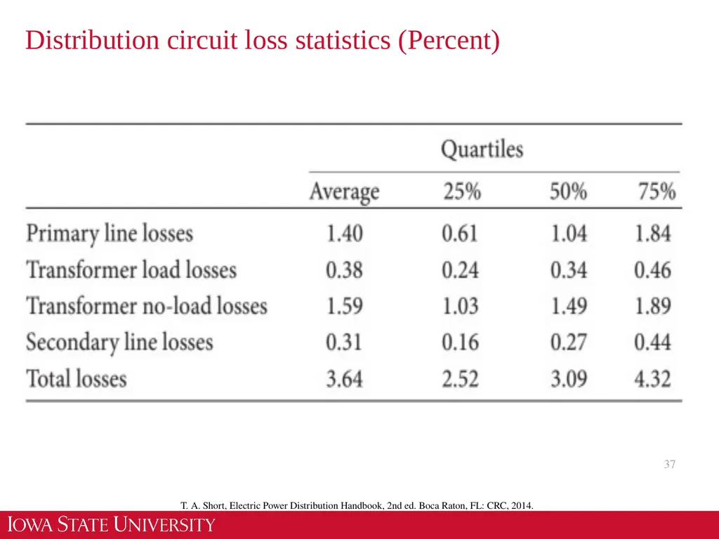
Distribution circuit loss statistics (Percent) 37 T. A. Short, Electric Power Distribution Handbook, 2nd ed. Boca Raton, FL: CRC, 2014.<br>
38
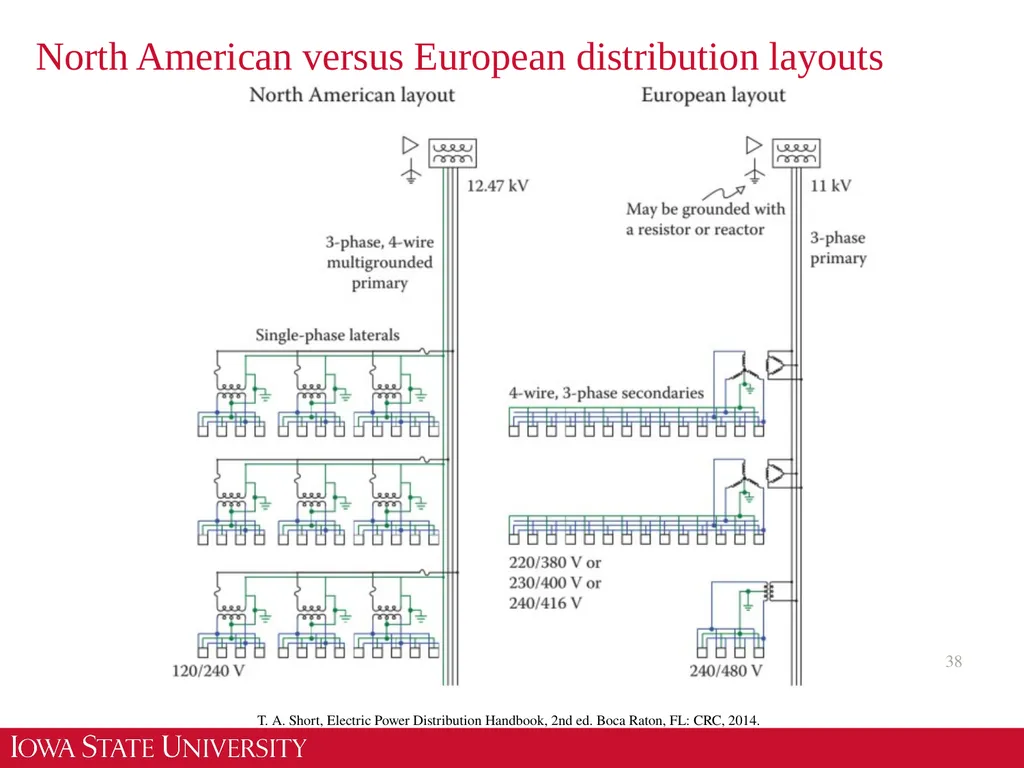
North American versus European distribution layouts 38 T. A. Short, Electric Power Distribution Handbook, 2nd ed. Boca Raton, FL: CRC, 2014.<br>
39
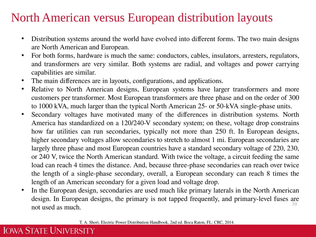
North American versus European distribution layouts 39 T. A. Short, Electric Power Distribution Handbook, 2nd ed. Boca Raton, FL: CRC, 2014. Distribution systems around the world have evolved into different forms. The two main designs are North American and European.
For both forms, hardware is much the same: conductors, cables, insulators, arresters, regulators, and transformers are very similar. Both systems are radial, and voltages and power carrying capabilities are similar.
The main differences are in layouts, configurations, and applications.
Relative to North American designs, European systems have larger transformers and more customers per transformer. Most European transformers are three phase and on the order of 300 to 1000 kVA, much larger than the typical North American 25- or 50-kVA single-phase units.
Secondary voltages have motivated many of the differences in distribution systems. North America has standardized on a 120/240-V secondary system; on these, voltage drop constrains how far utilities can run secondaries, typically not more than 250 ft. In European designs, higher secondary voltages allow secondaries to stretch to almost 1 mi. European secondaries are largely three phase and most European countries have a standard secondary voltage of 220, 230, or 240 V, twice the North American standard. With twice the voltage, a circuit feeding the same load can reach 4 times the distance. And, because three-phase secondaries can reach over twice the length of a single-phase secondary, overall, a European secondary can reach 8 times the length of an American secondary for a given load and voltage drop.
In the European design, secondaries are used much like primary laterals in the North American design. In European designs, the primary is not tapped frequently, and primary-level fuses are not used as much.<br>
40
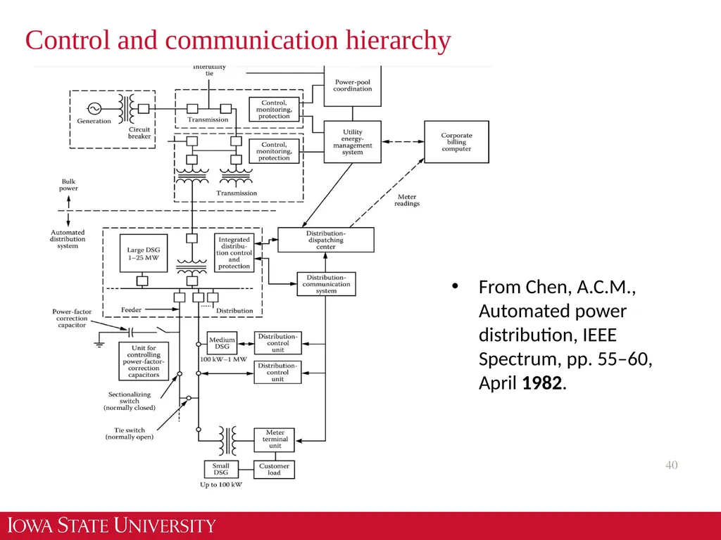
Control and communication hierarchy 40 From Chen, A.C.M., Automated power distribution, IEEE Spectrum, pp. 55–60, April 1982.<br>
41
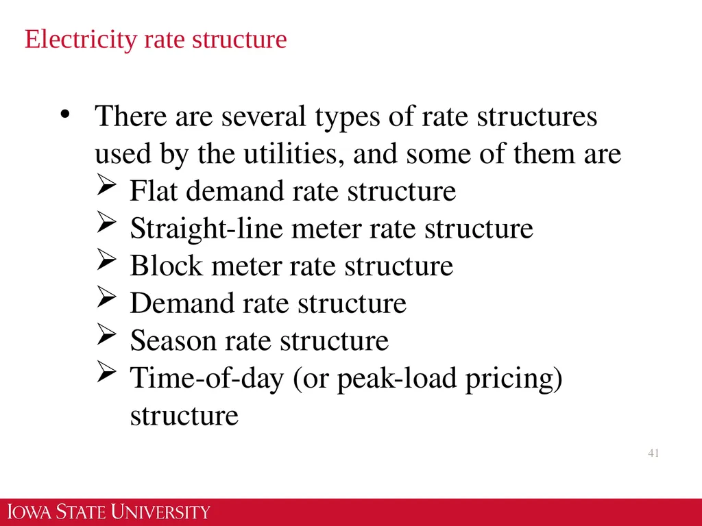
Electricity rate structure 41 There are several types of rate structures used by the utilities, and some of them are
Flat demand rate structure
Straight-line meter rate structure
Block meter rate structure
Demand rate structure
Season rate structure
Time-of-day (or peak-load pricing) structure<br>
Flat demand rate structure
Straight-line meter rate structure
Block meter rate structure
Demand rate structure
Season rate structure
Time-of-day (or peak-load pricing) structure<br>
42
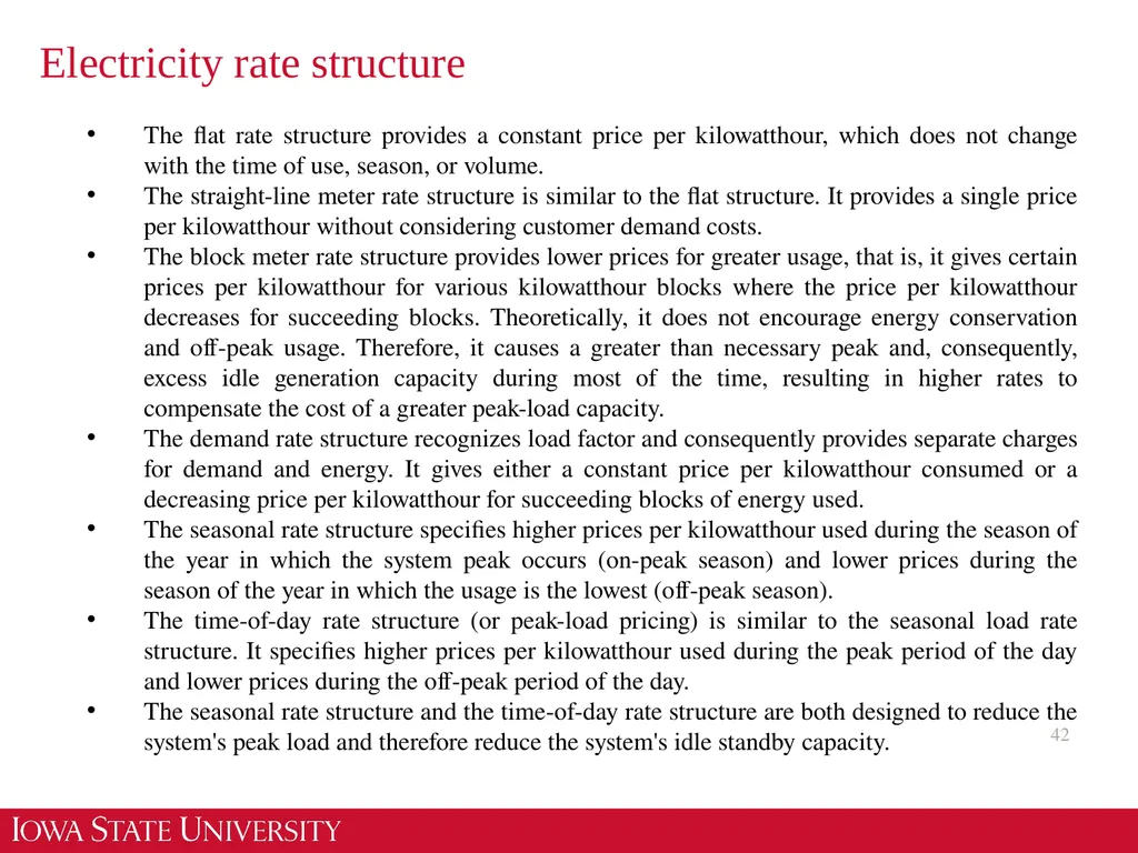
Electricity rate structure 42 The flat rate structure provides a constant price per kilowatthour, which does not change with the time of use, season, or volume.
The straight-line meter rate structure is similar to the flat structure. It provides a single price per kilowatthour without considering customer demand costs.
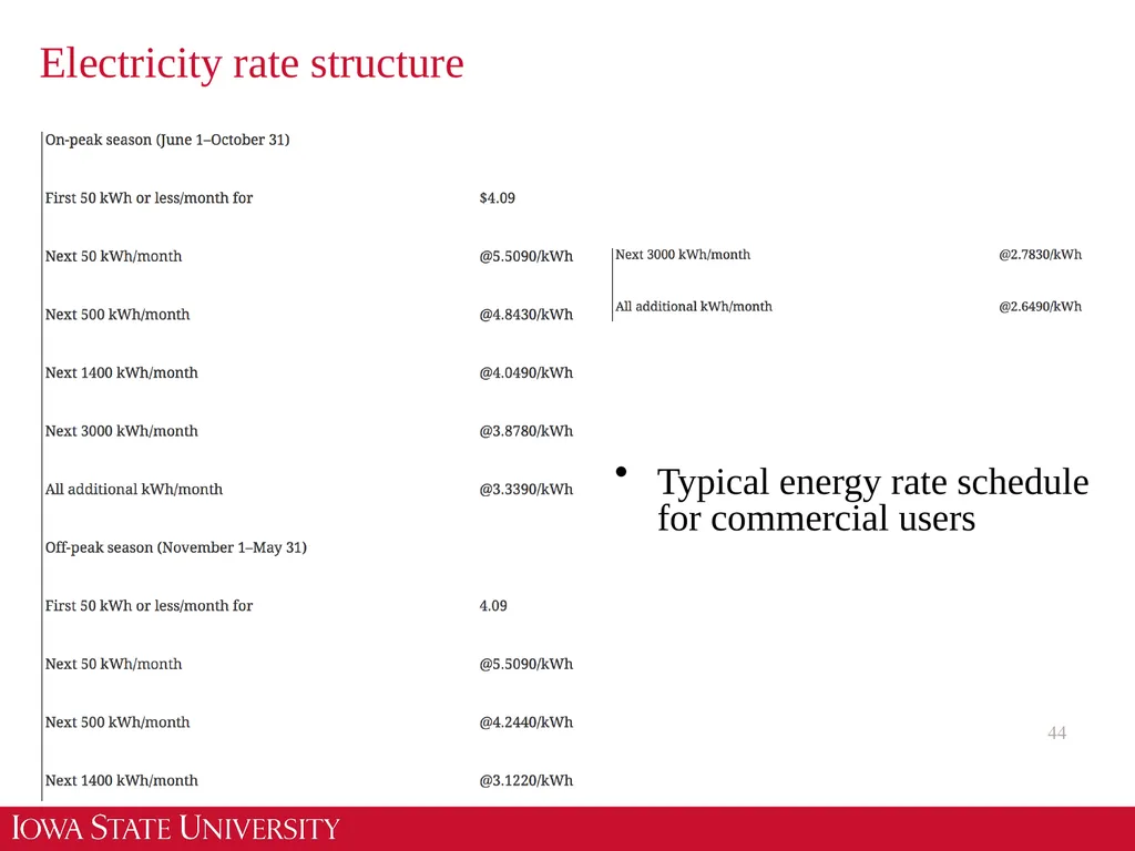
The block meter rate structure provides lower prices for greater usage, that is, it gives certain prices per kilowatthour for various kilowatthour blocks where the price per kilowatthour decreases for succeeding blocks. Theoretically, it does not encourage energy conservation and off-peak usage. Therefore, it causes a greater than necessary peak and, consequently, excess idle generation capacity during most of the time, resulting in higher rates to compensate the cost of a greater peak-load capacity.
The demand rate structure recognizes load factor and consequently provides separate charges for demand and energy. It gives either a constant price per kilowatthour consumed or a decreasing price per kilowatthour for succeeding blocks of energy used.
The seasonal rate structure specifies higher prices per kilowatthour used during the season of the year in which the system peak occurs (on-peak season) and lower prices during the season of the year in which the usage is the lowest (off-peak season).
The time-of-day rate structure (or peak-load pricing) is similar to the seasonal load rate structure. It specifies higher prices per kilowatthour used during the peak period of the day and lower prices during the off-peak period of the day.
The seasonal rate structure and the time-of-day rate structure are both designed to reduce the system's peak load and therefore reduce the system's idle standby capacity.<br>
43
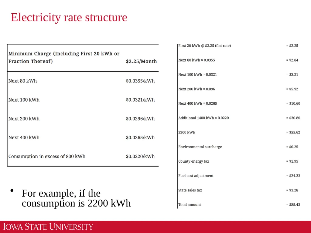
Electricity rate structure 43 For example, if the consumption is 2200 kWh<br>
44
Electricity rate structure 44 Typical energy rate schedule for commercial users<br>
45
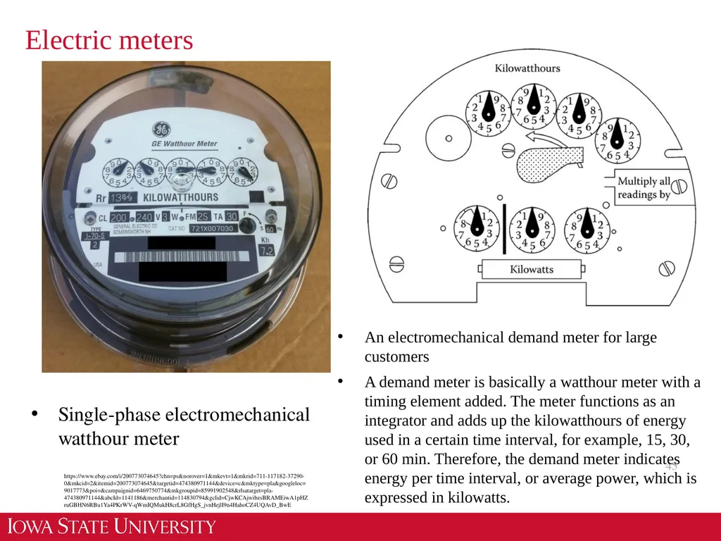
Electric meters 45 Single-phase electromechanical watthour meter https://www.ebay.com/i/200773074645?chn=ps&norover=1&mkevt=1&mkrid=711-117182-37290-0&mkcid=2&itemid=200773074645&targetid=474380971144&device=c&mktype=pla&googleloc=9017773&poi=&campaignid=6469750774&mkgroupid=85991902548&rlsatarget=pla-474380971144&abcId=1141186&merchantid=114830794&gclid=CjwKCAjwibzsBRAMEiwA1pHZruGBHN6RBu1Ya4PKrWV-qWmIQMukH8crL8GfHgS_jvnHejlI9n4HahoCZ4UQAvD_BwE An electromechanical demand meter for large customers
A demand meter is basically a watthour meter with a timing element added. The meter functions as an integrator and adds up the kilowatthours of energy used in a certain time interval, for example, 15, 30, or 60 min. Therefore, the demand meter indicates energy per time interval, or average power, which is expressed in kilowatts.<br>
A demand meter is basically a watthour meter with a timing element added. The meter functions as an integrator and adds up the kilowatthours of energy used in a certain time interval, for example, 15, 30, or 60 min. Therefore, the demand meter indicates energy per time interval, or average power, which is expressed in kilowatts.<br>
46
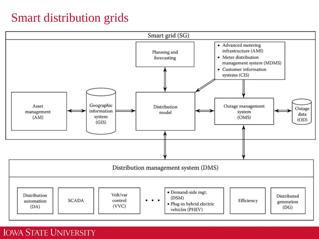
Smart distribution grids 46<br>
47
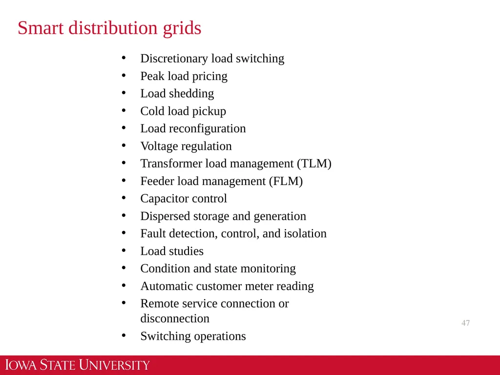
Smart distribution grids 47 Discretionary load switching
Peak load pricing
Load shedding
Cold load pickup
Load reconfiguration
Voltage regulation
Transformer load management (TLM)
Feeder load management (FLM)
Capacitor control
Dispersed storage and generation
Fault detection, control, and isolation
Load studies
Condition and state monitoring
Automatic customer meter reading
Remote service connection or disconnection
Switching operations<br>
48
48 Thank you!<br>