
Engine Break-In Guidance and Procedures 1 The



Description: Engine Break-In Guidance and Procedures 1 The Civil Air Patrol fleet of 545 powered aircraft experiences 40 engine replacements per year. Each of these replacements cost 53,000 each representing a significant CAP investment. CAP had no
Related Topics
Download Presentation
"Engine Break-In Guidance and Procedures 1 The" is the property of its rightful owner. Permission is granted to download and print the materials on this website for personal, non-commercial use only, and to display it on your personal computer provided you do not modify the materials and that you retain all copyright notices contained in the materials. By downloading content from our website, you accept the terms of this agreement.
Presentation Transcript
slide1. Engine Break-In Guidance and Procedures 1<br>
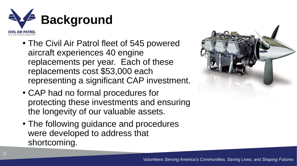
slide2. The Civil Air Patrol fleet of 545 powered aircraft experiences 40 engine replacements per year. Each of these replacements cost $53,000 each representing a significant CAP investment.
CAP had no formal procedures for protecting these investments and ensuring the longevity of our valuable assets.
The following guidance and procedures were developed to address that shortcoming. Background 2<br>
slide3. The goal of the break-in process is to wear the piston rings into the cylinder surface in a process known as ring-to-bore seating.
Piston rings and cylinder wall surfaces are not completely smooth from manufacturing. The break-in process removes high spots and creates a tight gas seal that is necessary for normal engine operation.
This process is usually completed in the first 50 flight hours with most ring seating occurring within the first 10 hours making initial engine operation a critical step of this process. Objective 3<br>
slide4. Aircraft that have a new or overhaul engine or an engine that has had cylinder repair/replacement (single or multiple) are required to follow the engine break-in procedures to preserve the life of the engine to maximum extent possible.
The aircraft will be analyzed by CAP/LGM staff for oil consumption, oil temperature and cylinder head temperature stabilization over the course of the first 10 tach hours post component replacement.
Once stabilization has occurred, CAP/LGM Director, Rob Fleming, will release the aircraft from the break-in profile.
These flights will all be performed utilizing A9 funding with the aircraft prohibited from other missions during the break-in profile. Guidance 4<br>
slide5. A training course has been created in Absorb to educate pilots on the proper steps and procedures of the break-in process.
This training is mandatory for every pilot that will participate in break-in flights.
The training course is an annually recurring event tied directly to pilot qualifications. Training 5<br>
slide6. Once an aircraft has been identified as new, overhauled or cylinder rework has occurred; the Maintenance Officer, MX Coordinator or Plans Scheduling and Documentation will generate a discrepancy in the aircraft records that the aircraft requires engine break-in.
During the new/overhauled engine break-in phase, certain operational restrictions and data collection requirements are mandatory. Only flight crew specifically authorized are permitted to operate the airplane during the break in phase utilizing A9 sorties only. This discrepancy will be closed when CAP/LGM is satisfied that the break in phase is concluded.
Pilots will use one of four checklists during all break-in flights, which dictate flight parameters for the aircraft, engine, and propeller. Proper adherence to these procedures is essential to avoid glazing and ensure correct ring seating. Procedures 6<br>
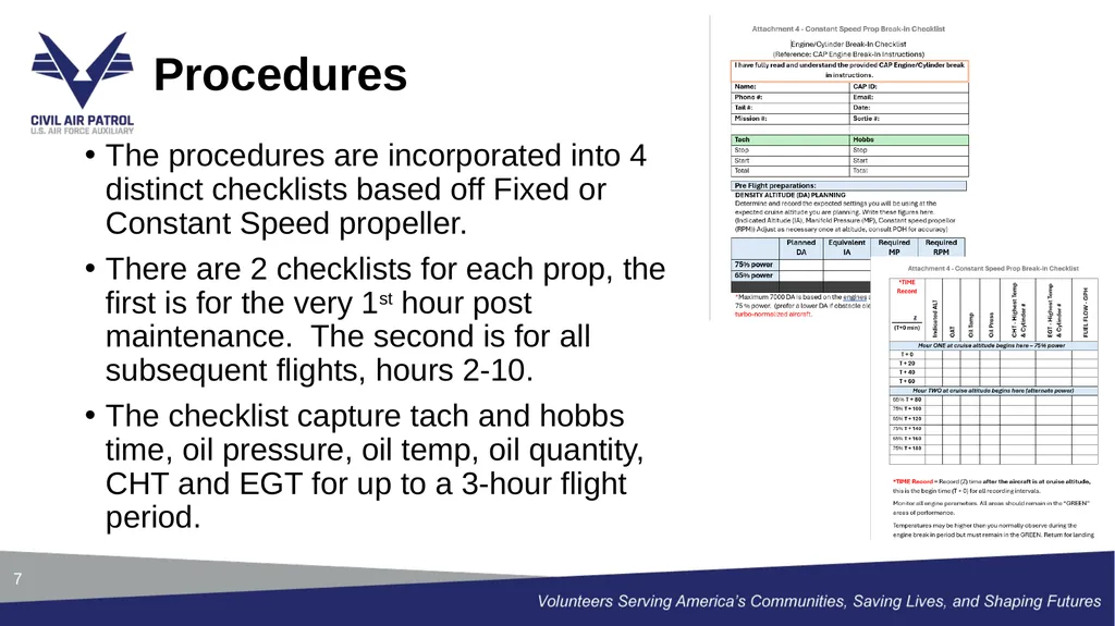
slide7. Procedures 7 The procedures are incorporated into 4 distinct checklists based off Fixed or Constant Speed propeller.
There are 2 checklists for each prop, the first is for the very 1st hour post maintenance. The second is for all subsequent flights, hours 2-10.
The checklist capture tach and hobbs time, oil pressure, oil temp, oil quantity, CHT and EGT for up to a 3-hour flight period.<br>
slide8. The engine, during break-in, will consume oil at a decreasing rate as it wears together. Oil loss is measured in quarts per flight hour. Measuring and observing when oil consumption stabilizes is the critical factor in determining when engine break has been completed.
During the preflight inspection annotate the oil level and if any oil is added. The oil level for each engine is found in the aircraft POH. Reference guide: 206’s=11 qts/182’s=8 qts/172’s=8 qts
The oil consumed on the previous flight will be calculated against the flight time to graph how much oil is being consumed per flight hour. Procedures 8<br>
slide9. The first hour of flight is to be conducted within glide distance of the departure airport runway at a power setting of 75%.
Subsequent flights allow for repositioning of the aircraft alternating between 75% and 65% power at 20 min intervals.
Throughout each flight, the pilot not flying will record OAT, PA, Oil Temp, Oil Press, CHT Temp, EGT Temp and Fuel flow.
This data is to be recorded every 20 mins during the duration of the flight at cruise altitude. Expect high fuel flow, near full rich mixture and low CHT temperatures.
*At no time should recording engine perimeters jeopardize flight safety. Procedures 9<br>
slide10. All flight data is collected in a database called Smartsheets.
https://app.smartsheet.com/b/form/630e9e4368b34a84ab74cd0d131c7bda
The hyperlink above, also on each checklist, will allow the pilot to input all collected data directly into the database. If there is a technical issue, forward all data to LGPSD@capnhq.gov
This database will remain as a repository for all aircraft data to analyze for trends and historical reference. Procedures 10<br>
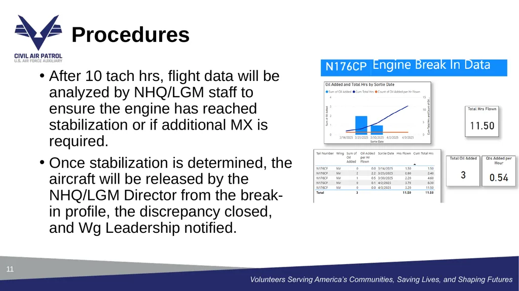
slide11. After 10 tach hrs, flight data will be analyzed by NHQ/LGM staff to ensure the engine has reached stabilization or if additional MX is required.
Once stabilization is determined, the aircraft will be released by the NHQ/LGM Director from the break-in profile, the discrepancy closed, and Wg Leadership notified. Procedures 11<br>
slide12. All break-in publications are located on the CAP Publications page.
https://www.gocivilairpatrol.com/members/publications/other-publications-1709
Logistics Section
Engine Break-In Procedure (May 25 Version 9)
Engine Break-In Checklist for Verification Flight - Fixed Pitch Prop (Feb 25 Version 5)
Engine Break-In Checklist - Fixed Pitch Prop (Feb 25 Version 5)
Engine Break-In Checklist for Verification Flight - Constant Speed Prop (Feb 25 Version 5)
Engine Break-In Checklist - Constant Speed Prop (May 25 Version 7) Publications 12<br>
slide13. Rob Fleming, Director Aviation Maintenance and Management
jfleming@capnhq.gov
Zachary Motley, Plans Scheduling and Documentation PM
zmotley@capnhq.gov
Rodger Kirkpatrick, Aircraft Maintenance PM
rkirkpatrick@capnhq.gov
Joe Keller, Standards and Evaluations PM
jkeller@capnhq.gov Points of Contact 13<br>
slide2. The Civil Air Patrol fleet of 545 powered aircraft experiences 40 engine replacements per year. Each of these replacements cost $53,000 each representing a significant CAP investment.
CAP had no formal procedures for protecting these investments and ensuring the longevity of our valuable assets.
The following guidance and procedures were developed to address that shortcoming. Background 2<br>
slide3. The goal of the break-in process is to wear the piston rings into the cylinder surface in a process known as ring-to-bore seating.
Piston rings and cylinder wall surfaces are not completely smooth from manufacturing. The break-in process removes high spots and creates a tight gas seal that is necessary for normal engine operation.
This process is usually completed in the first 50 flight hours with most ring seating occurring within the first 10 hours making initial engine operation a critical step of this process. Objective 3<br>
slide4. Aircraft that have a new or overhaul engine or an engine that has had cylinder repair/replacement (single or multiple) are required to follow the engine break-in procedures to preserve the life of the engine to maximum extent possible.
The aircraft will be analyzed by CAP/LGM staff for oil consumption, oil temperature and cylinder head temperature stabilization over the course of the first 10 tach hours post component replacement.
Once stabilization has occurred, CAP/LGM Director, Rob Fleming, will release the aircraft from the break-in profile.
These flights will all be performed utilizing A9 funding with the aircraft prohibited from other missions during the break-in profile. Guidance 4<br>
slide5. A training course has been created in Absorb to educate pilots on the proper steps and procedures of the break-in process.
This training is mandatory for every pilot that will participate in break-in flights.
The training course is an annually recurring event tied directly to pilot qualifications. Training 5<br>
slide6. Once an aircraft has been identified as new, overhauled or cylinder rework has occurred; the Maintenance Officer, MX Coordinator or Plans Scheduling and Documentation will generate a discrepancy in the aircraft records that the aircraft requires engine break-in.
During the new/overhauled engine break-in phase, certain operational restrictions and data collection requirements are mandatory. Only flight crew specifically authorized are permitted to operate the airplane during the break in phase utilizing A9 sorties only. This discrepancy will be closed when CAP/LGM is satisfied that the break in phase is concluded.
Pilots will use one of four checklists during all break-in flights, which dictate flight parameters for the aircraft, engine, and propeller. Proper adherence to these procedures is essential to avoid glazing and ensure correct ring seating. Procedures 6<br>
slide7. Procedures 7 The procedures are incorporated into 4 distinct checklists based off Fixed or Constant Speed propeller.
There are 2 checklists for each prop, the first is for the very 1st hour post maintenance. The second is for all subsequent flights, hours 2-10.
The checklist capture tach and hobbs time, oil pressure, oil temp, oil quantity, CHT and EGT for up to a 3-hour flight period.<br>
slide8. The engine, during break-in, will consume oil at a decreasing rate as it wears together. Oil loss is measured in quarts per flight hour. Measuring and observing when oil consumption stabilizes is the critical factor in determining when engine break has been completed.
During the preflight inspection annotate the oil level and if any oil is added. The oil level for each engine is found in the aircraft POH. Reference guide: 206’s=11 qts/182’s=8 qts/172’s=8 qts
The oil consumed on the previous flight will be calculated against the flight time to graph how much oil is being consumed per flight hour. Procedures 8<br>
slide9. The first hour of flight is to be conducted within glide distance of the departure airport runway at a power setting of 75%.
Subsequent flights allow for repositioning of the aircraft alternating between 75% and 65% power at 20 min intervals.
Throughout each flight, the pilot not flying will record OAT, PA, Oil Temp, Oil Press, CHT Temp, EGT Temp and Fuel flow.
This data is to be recorded every 20 mins during the duration of the flight at cruise altitude. Expect high fuel flow, near full rich mixture and low CHT temperatures.
*At no time should recording engine perimeters jeopardize flight safety. Procedures 9<br>
slide10. All flight data is collected in a database called Smartsheets.
https://app.smartsheet.com/b/form/630e9e4368b34a84ab74cd0d131c7bda
The hyperlink above, also on each checklist, will allow the pilot to input all collected data directly into the database. If there is a technical issue, forward all data to LGPSD@capnhq.gov
This database will remain as a repository for all aircraft data to analyze for trends and historical reference. Procedures 10<br>
slide11. After 10 tach hrs, flight data will be analyzed by NHQ/LGM staff to ensure the engine has reached stabilization or if additional MX is required.
Once stabilization is determined, the aircraft will be released by the NHQ/LGM Director from the break-in profile, the discrepancy closed, and Wg Leadership notified. Procedures 11<br>
slide12. All break-in publications are located on the CAP Publications page.
https://www.gocivilairpatrol.com/members/publications/other-publications-1709
Logistics Section
Engine Break-In Procedure (May 25 Version 9)
Engine Break-In Checklist for Verification Flight - Fixed Pitch Prop (Feb 25 Version 5)
Engine Break-In Checklist - Fixed Pitch Prop (Feb 25 Version 5)
Engine Break-In Checklist for Verification Flight - Constant Speed Prop (Feb 25 Version 5)
Engine Break-In Checklist - Constant Speed Prop (May 25 Version 7) Publications 12<br>
slide13. Rob Fleming, Director Aviation Maintenance and Management
jfleming@capnhq.gov
Zachary Motley, Plans Scheduling and Documentation PM
zmotley@capnhq.gov
Rodger Kirkpatrick, Aircraft Maintenance PM
rkirkpatrick@capnhq.gov
Joe Keller, Standards and Evaluations PM
jkeller@capnhq.gov Points of Contact 13<br>