Finite element simulation of particle impact on protective elastomer coatings for wind turbine blades Ali Eftekhar Introduction to leading edge erosion 2 Wind turbine blade length has increased over time to generate more power and
"Finite element simulation of particle impact on" is the property of its rightful owner. Permission is granted to
download and print the materials on this website for personal, non-commercial use only, and to display it
on your personal computer provided you do not modify the materials and that you retain all copyright
notices contained in the materials. By downloading content from our website, you accept the terms of this
agreement.
Presentation Transcript
01
Finite element simulation of particle impact on protective elastomer coatings for wind turbine blades Ali Eftekhar<br>
02
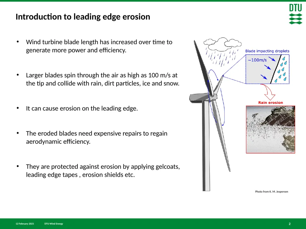
Introduction to leading edge erosion 2 Wind turbine blade length has increased over time to generate more power and efficiency.
Larger blades spin through the air as high as 100 m/s at the tip and collide with rain, dirt particles, ice and snow.
It can cause erosion on the leading edge.
The eroded blades need expensive repairs to regain aerodynamic efficiency.
They are protected against erosion by applying gelcoats, leading edge tapes , erosion shields etc. Photo from K. M. Jespersen<br>
03
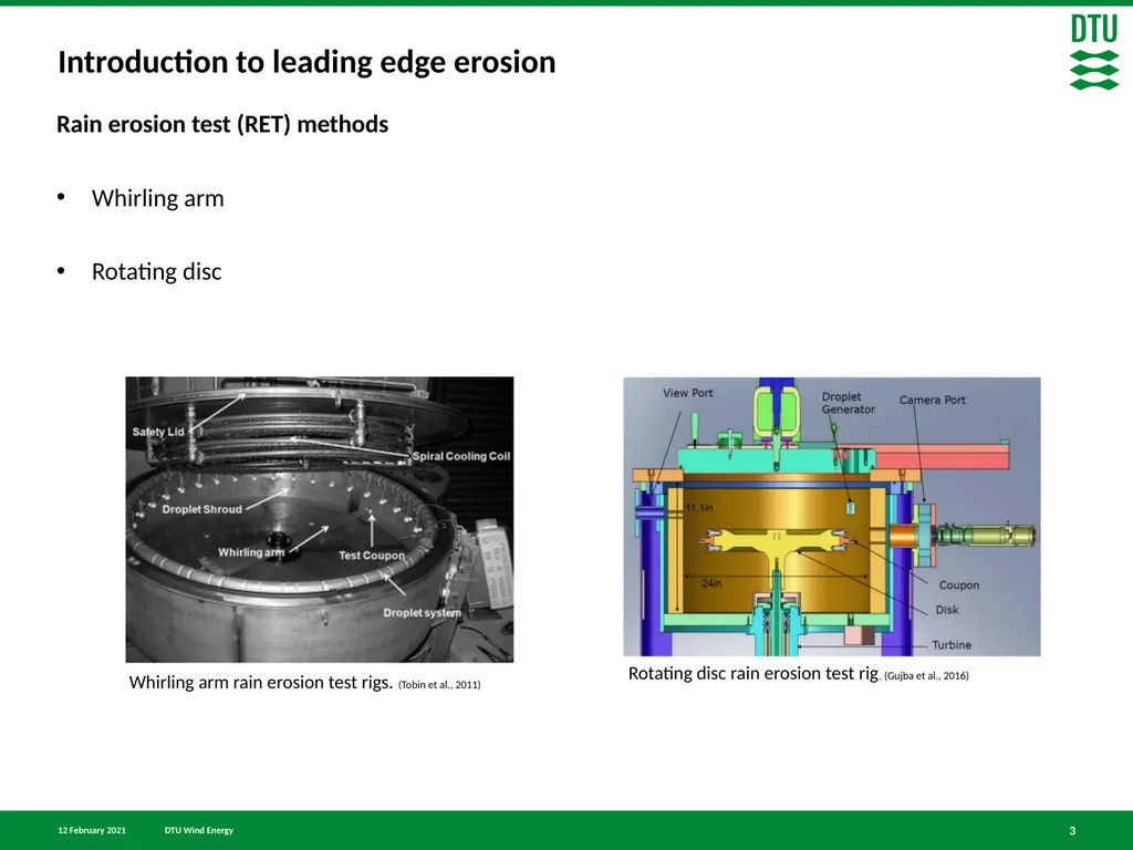
Introduction to leading edge erosion 3 Rain erosion test (RET) methods
Whirling arm
Rotating disc Rotating disc rain erosion test rig. (Gujba et al., 2016)<br>
04
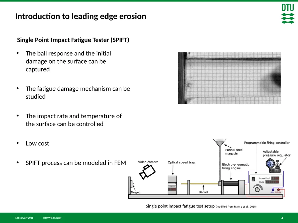
Introduction to leading edge erosion 4 Single Point Impact Fatigue Tester (SPIFT) Single point impact fatigue test setup (modified from Fraisse et al., 2018) The ball response and the initial damage on the surface can be captured
The fatigue damage mechanism can be studied
The impact rate and temperature of the surface can be controlled
Low cost
SPIFT process can be modeled in FEM<br>
05
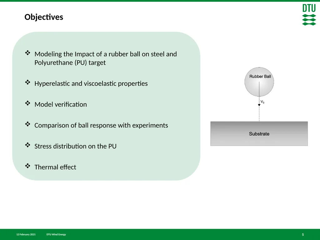
Objectives 5 Modeling the Impact of a rubber ball on steel and Polyurethane (PU) target
Hyperelastic and viscoelastic properties
Model verification
Comparison of ball response with experiments
Stress distribution on the PU
Thermal effect<br>
06
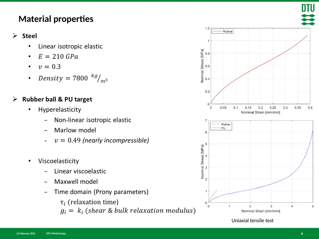
Material properties 6<br>
07
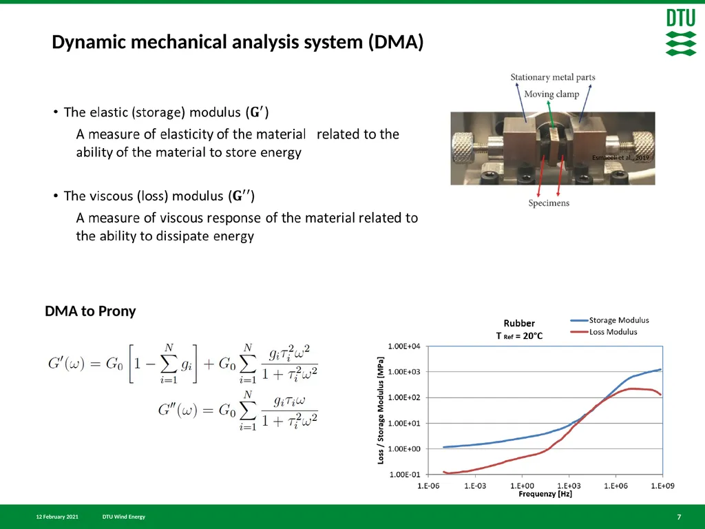
7 Dynamic mechanical analysis system (DMA) DMA to Prony Esmaeeli et al., 2019<br>
08
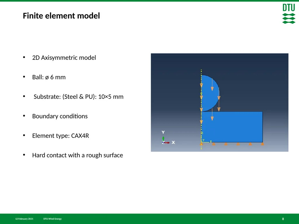
Finite element model 8 2D Axisymmetric model
Ball: ø 6 mm
Substrate: (Steel & PU): 10×5 mm
Boundary conditions
Element type: CAX4R
Hard contact with a rough surface<br>
09
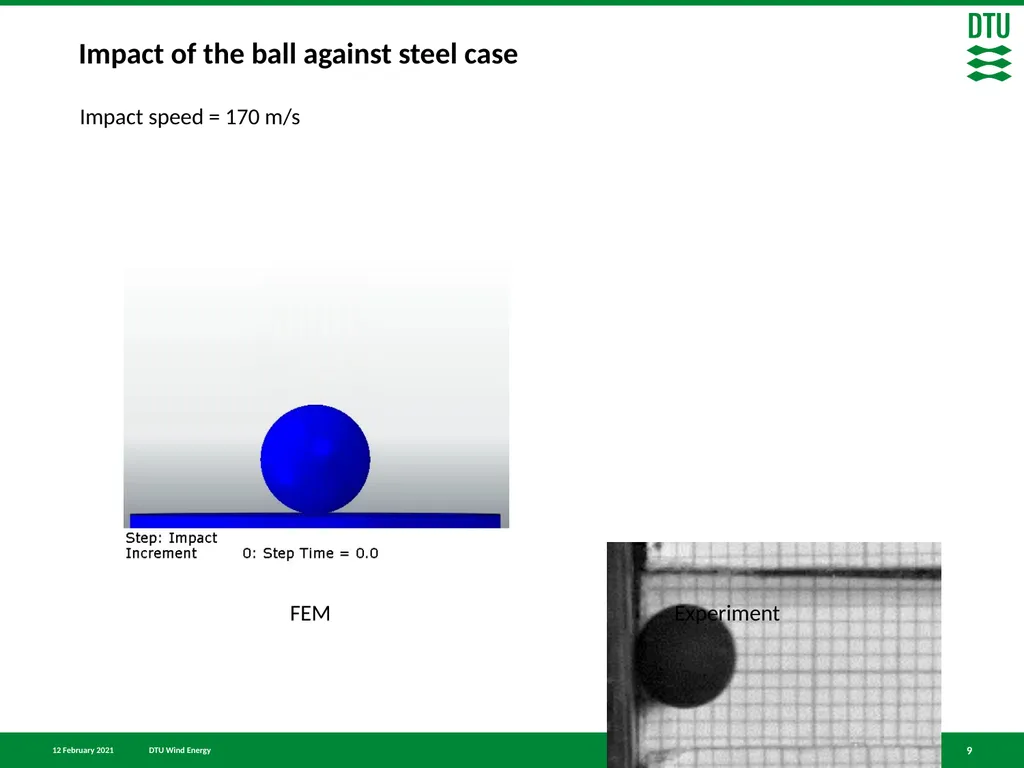
Impact of the ball against steel case 9 FEM Experiment Impact speed = 170 m/s<br>
10
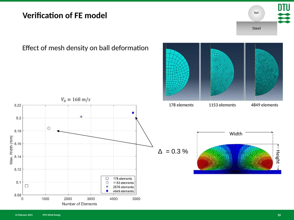
Verification of FE model Effect of mesh density on ball deformation 10 Δ = 0.3 %<br>
11
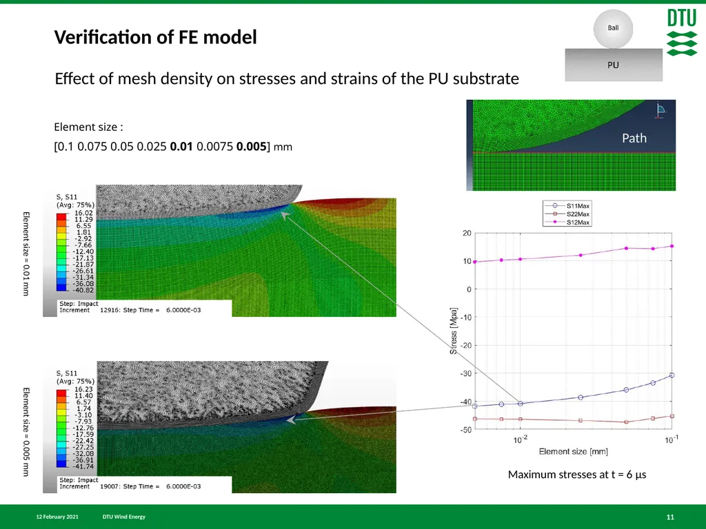
Verification of FE model Effect of mesh density on stresses and strains of the PU substrate 11 Element size :
[0.1 0.075 0.05 0.025 0.01 0.0075 0.005] mm Maximum stresses at t = 6 μs Path<br>
12
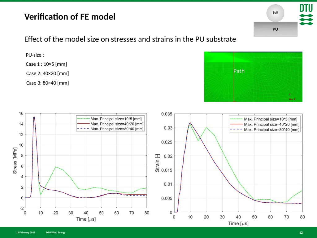
Verification of FE model Effect of the model size on stresses and strains in the PU substrate 12 Path<br>
13
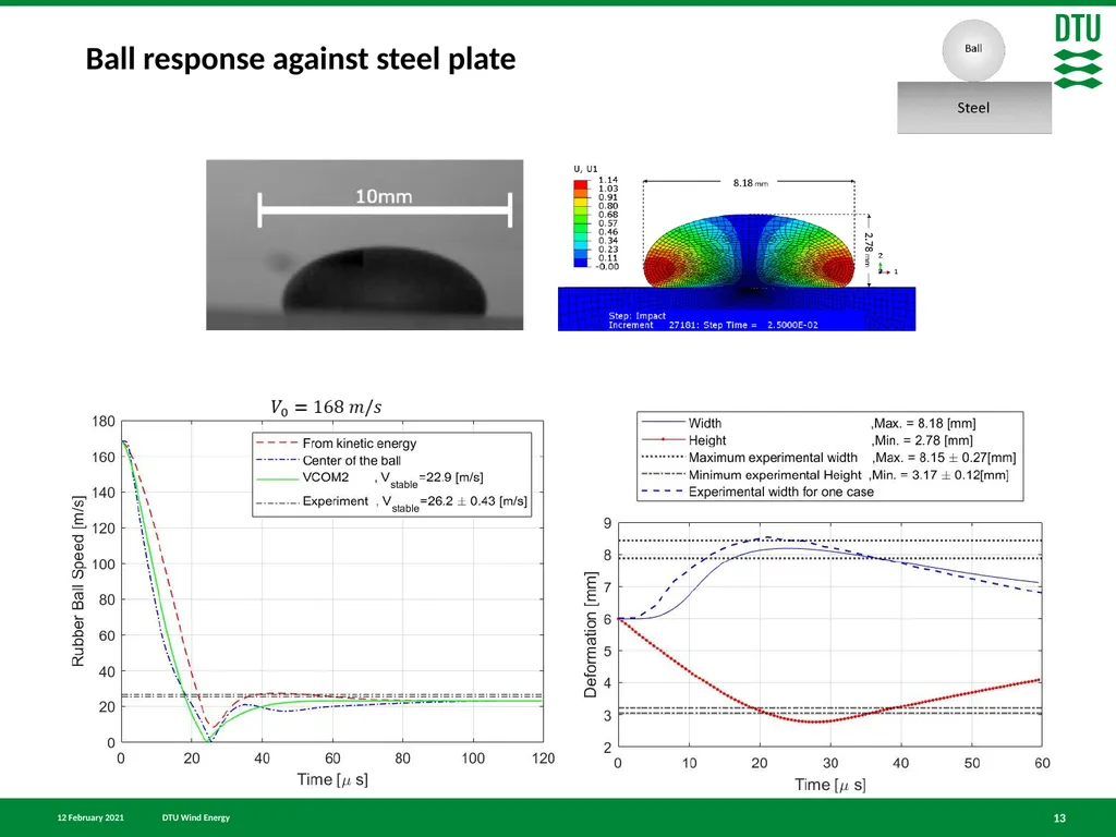
Ball response against steel plate 13<br>
14
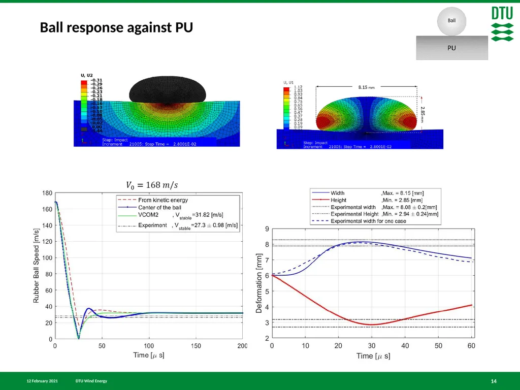
Ball response against PU 14<br>
15
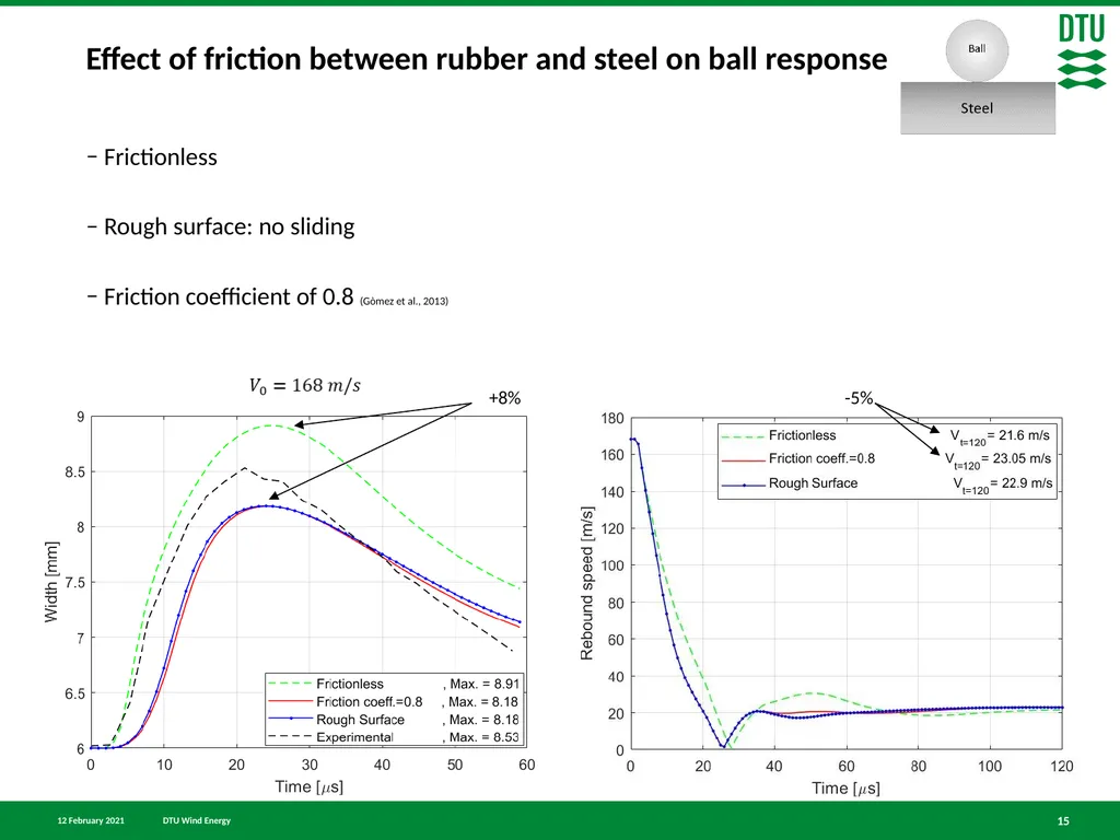
Effect of friction between rubber and steel on ball response Frictionless
Rough surface: no sliding
Friction coefficient of 0.8 (Gòmez et al., 2013) 15 +8% -5%<br>
16
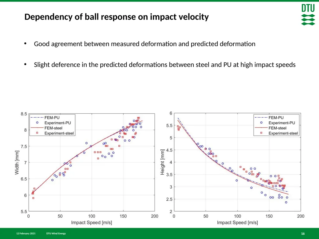
Dependency of ball response on impact velocity 16 Good agreement between measured deformation and predicted deformation
Slight deference in the predicted deformations between steel and PU at high impact speeds<br>
17
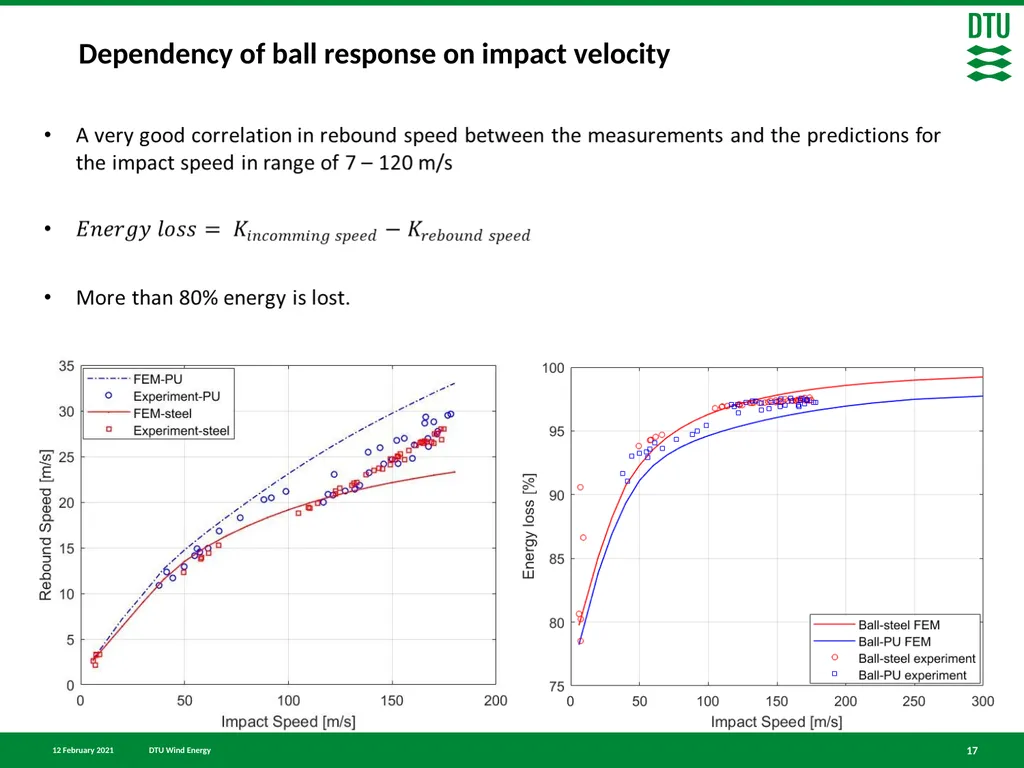
Dependency of ball response on impact velocity 17<br>
18
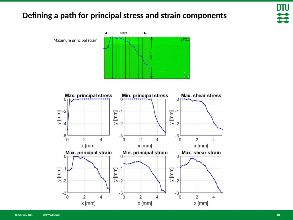
Defining a path for principal stress and strain components 18 Maximum principal strain<br>
19
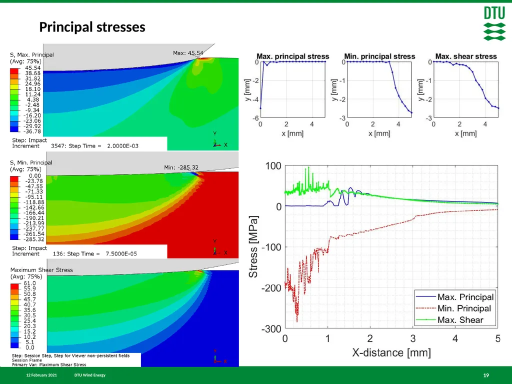
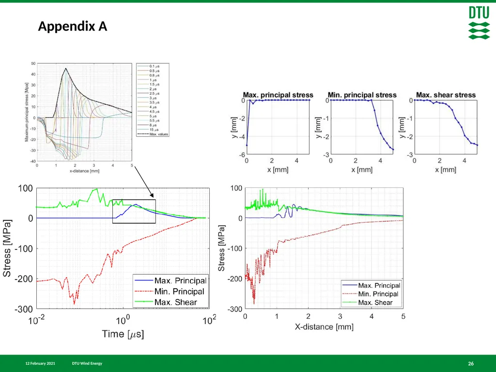
Principal stresses 19<br>
20
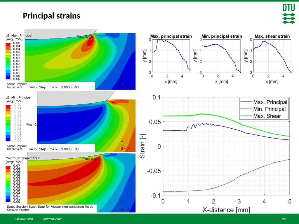
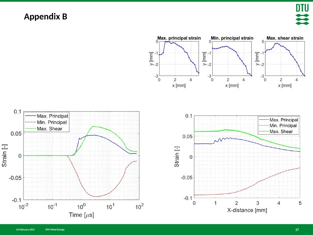
Principal strains 20<br>
21
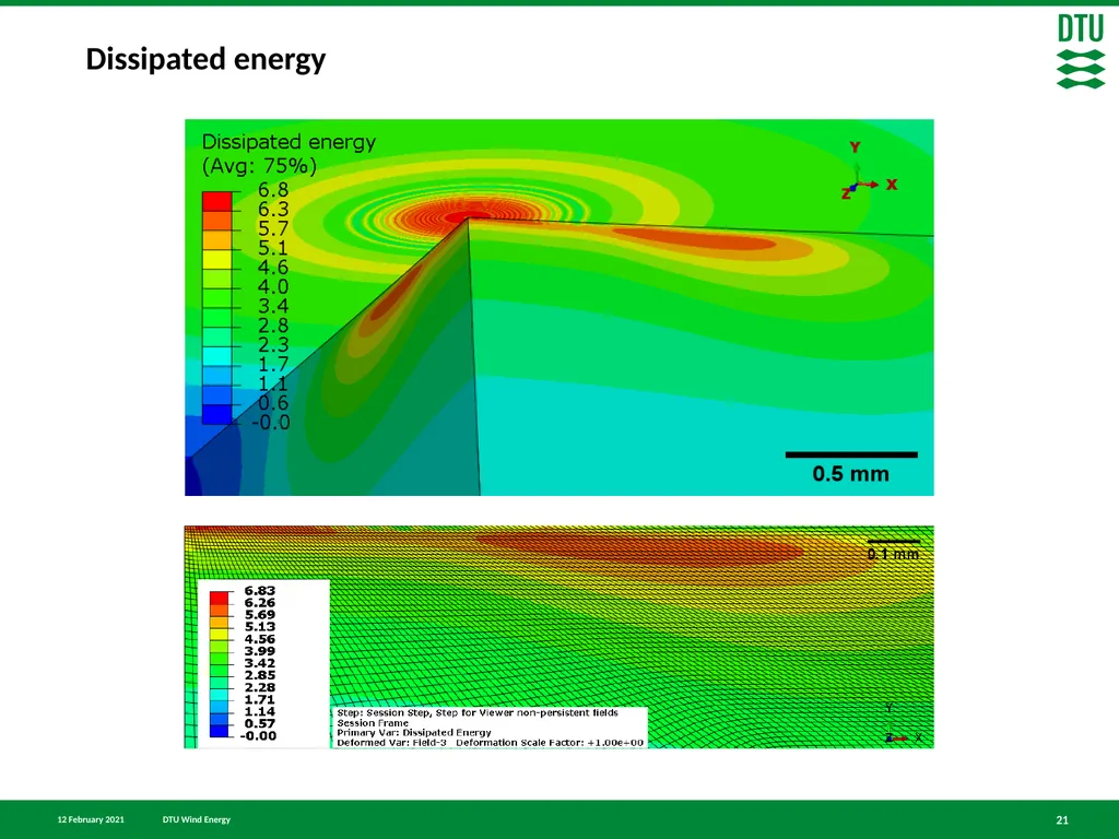
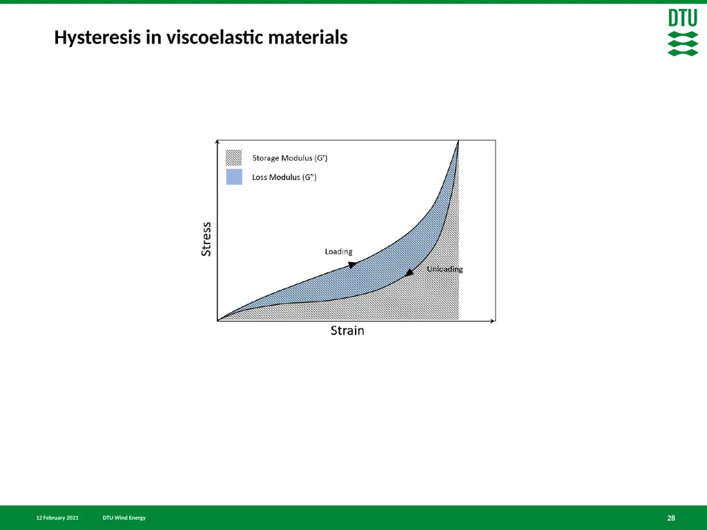
21 Dissipated energy<br>
22
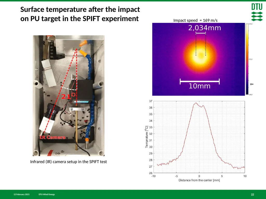
Surface temperature after the impact on PU target in the SPIFT experiment 22 Impact speed = 169 m/s Infrared (IR) camera setup in the SPIFT test<br>
23
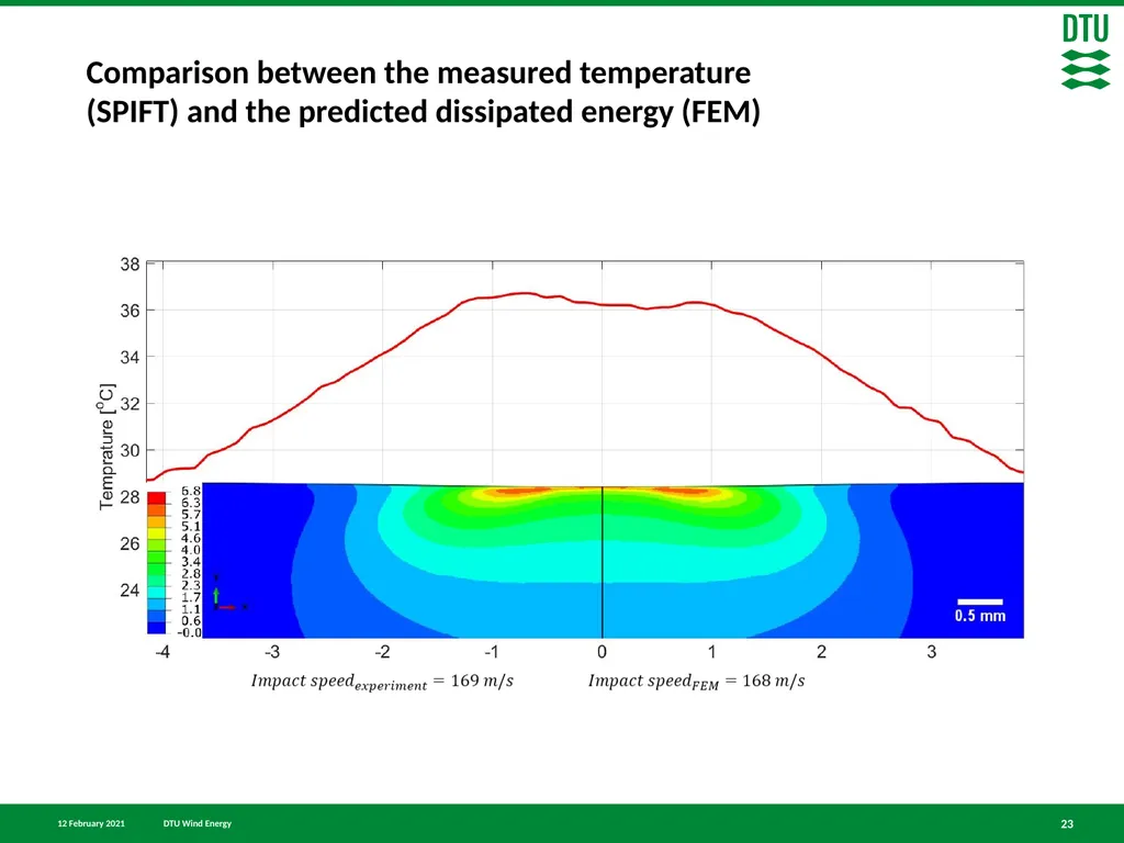
Comparison between the measured temperature (SPIFT) and the predicted dissipated energy (FEM) 23<br>
24
Conclusion 24 Finite element model of a rubber ball impacting coating substrate was developed and validated.
We were able to capture about 97% energy loss in rubber ball at high impact rates.
Different paths through the critical points in the substrate were obtained
The critical stress and strain values were in radius of 1.5 mm and in depth of 0.5 mm
A very good agreement between the dissipated energy in the FE model and the measured temperature of the PU surface in the SPIFT experiment were able to capture.<br>
25
25 Thank you for your attention! Supervisor
Associate Professor Lars Pilgaard Mikkelsen
Co supervisors
Scientist Kristine Munk Jespersen
Senior Development Engineer Jakob Ilsted Bech
Senior Scientist Leon Mishnaevsky
Experimental work and analysis
Scientist Nicolai Frost-Jensen Johansen<br>