Finite State Machines Hakim Weatherspoon CS 3410
Description: Finite State Machines Hakim Weatherspoon CS 3410 Computer Science Cornell University The slides are the product of many rounds of teaching CS 3410 by Professors Weatherspoon, Bala, Bracy, and Sirer. Goals for Today Finite State Machines
Related Topics
Download Presentation
"Finite State Machines Hakim Weatherspoon CS 3410" is the property of its rightful owner. Permission is granted to download and print the materials on this website for personal, non-commercial use only, and to display it on your personal computer provided you do not modify the materials and that you retain all copyright notices contained in the materials. By downloading content from our website, you accept the terms of this agreement.
Presentation Transcript
slide1. Finite State Machines Hakim Weatherspoon
CS 3410
Computer Science
Cornell University The slides are the product of many rounds of teaching CS 3410 by Professors Weatherspoon, Bala, Bracy, and Sirer.<br>
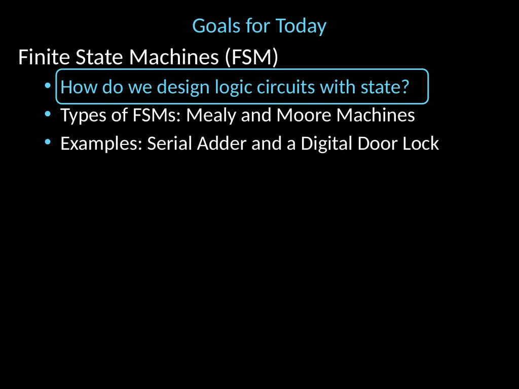
slide2. Goals for Today Finite State Machines (FSM)
How do we design logic circuits with state?
Types of FSMs: Mealy and Moore Machines
Examples: Serial Adder and a Digital Door Lock<br>
slide3. Finite State Machines<br>
slide4. Next Goal How do we design logic circuits with state?<br>
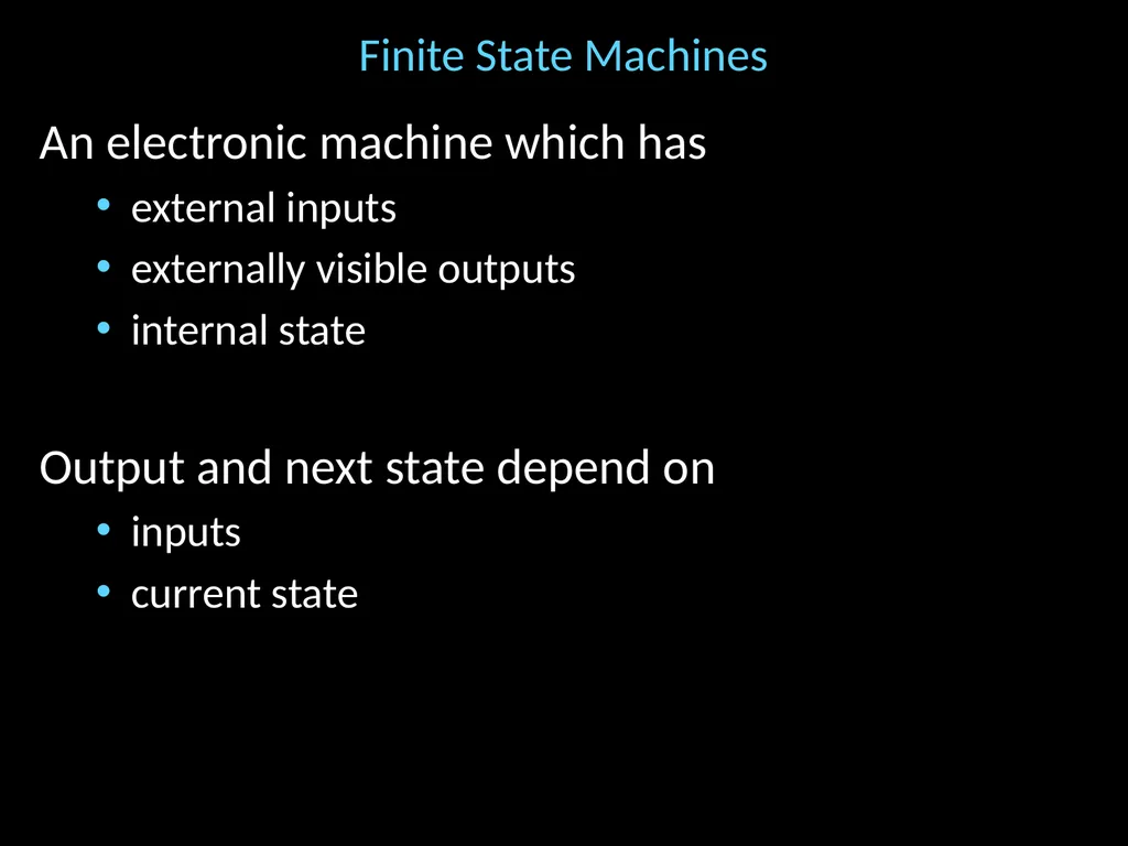
slide5. Finite State Machines An electronic machine which has
external inputs
externally visible outputs
internal state
Output and next state depend on
inputs
current state<br>
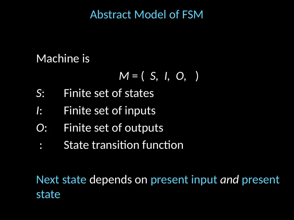
slide6. Abstract Model of FSM Machine is
M = ( S, I, O, )
S: Finite set of states
I: Finite set of inputs
O: Finite set of outputs
: State transition function
Next state depends on present input and present state<br>
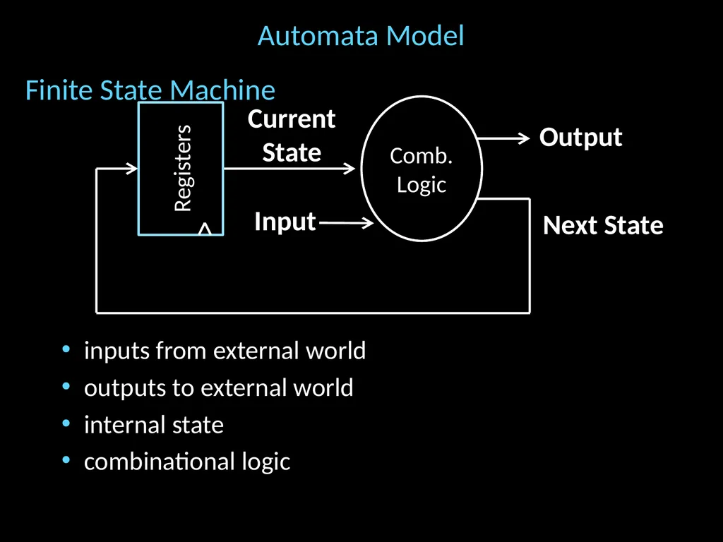
slide7. Automata Model Finite State Machine
inputs from external world
outputs to external world
internal state
combinational logic Next State Current State Input Output Registers Comb.Logic<br>
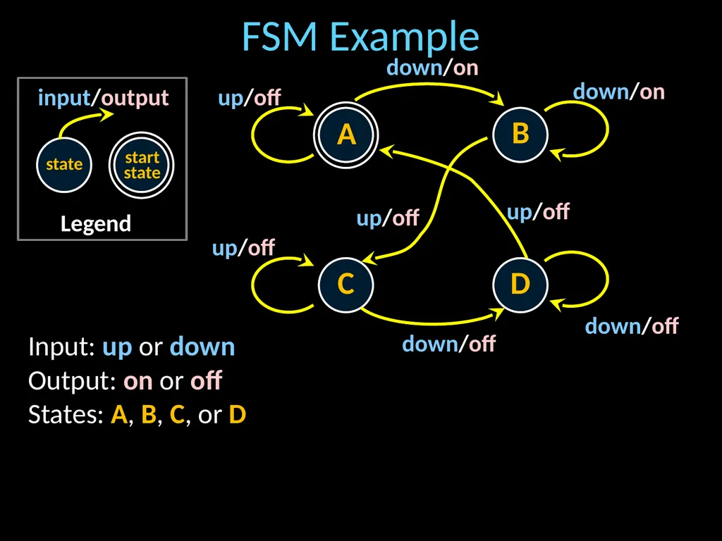
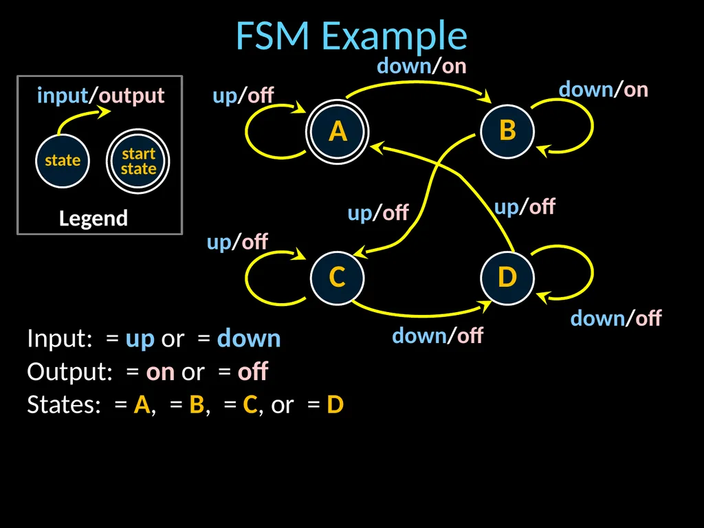
slide8. FSM Example Legend state input/output startstate A B C D down/on up/off down/on down/off up/off down/off up/off up/off Input: up or down
Output: on or off
States: A, B, C, or D<br>
slide9. FSM Example Legend state input/output startstate A B C D down/on up/off down/on down/off up/off down/off up/off up/off Input: = up or = down
Output: = on or = off
States: = A, = B, = C, or = D<br>
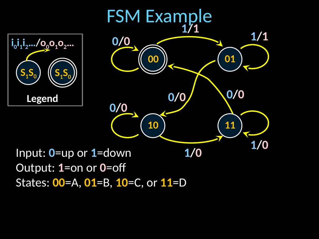
slide10. FSM Example Legend S1S0 i0i1i2…/o0o1o2… S1S0 00 01 10 11 1/1 0/0 1/1 1/0 0/0 1/0 0/0 0/0 Input: 0=up or 1=down
Output: 1=on or 0=off
States: 00=A, 01=B, 10=C, or 11=D<br>
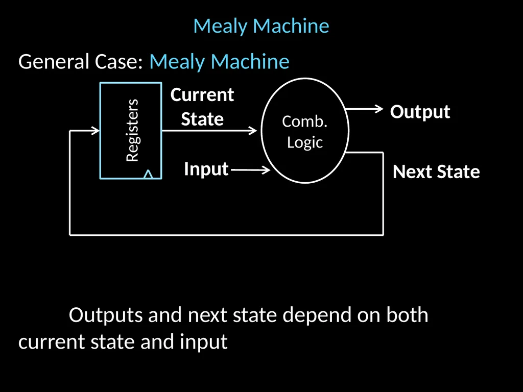
slide11. General Case: Mealy Machine
Outputs and next state depend on bothcurrent state and input Mealy Machine Next State Current State Input Output Registers Comb.Logic<br>
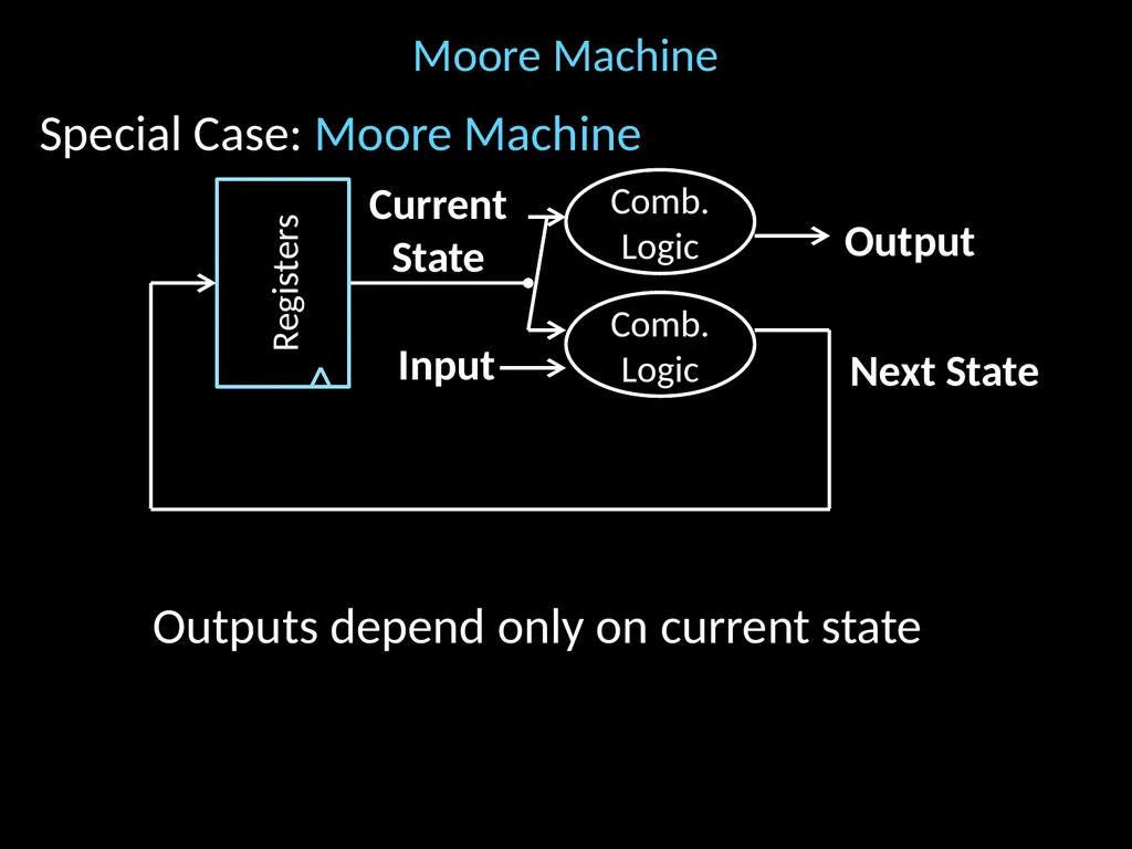
slide12. Moore Machine Special Case: Moore Machine
Outputs depend only on current state Next State Current State Input Output Registers Comb.Logic Comb.Logic<br>
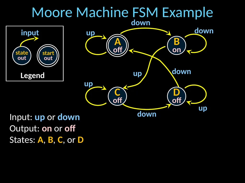
slide13. Moore Machine FSM Example Legend stateout input startout A off Bon C off D off down up down down up up down up Input: up or down
Output: on or off
States: A, B, C, or D<br>
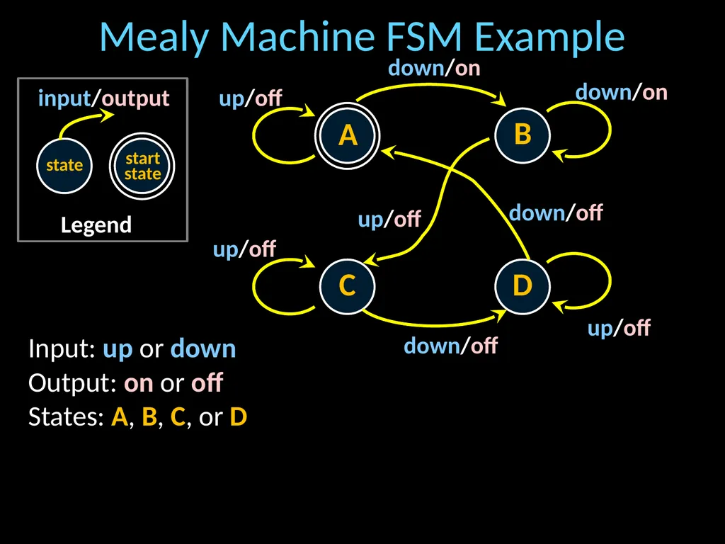
slide14. Mealy Machine FSM Example Legend state input/output startstate A B C D down/on up/off down/on down/off up/off up/off down/off up/off Input: up or down
Output: on or off
States: A, B, C, or D<br>
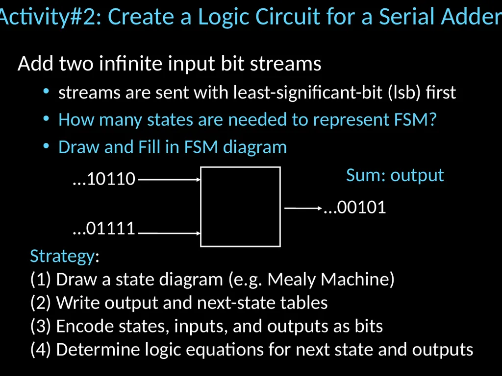
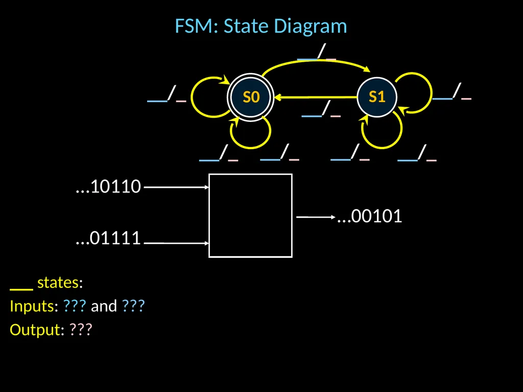
slide15. Activity#2: Create a Logic Circuit for a Serial Adder Add two infinite input bit streams
streams are sent with least-significant-bit (lsb) first
How many states are needed to represent FSM?
Draw and Fill in FSM diagram …10110 …01111 …00101 Strategy:
(1) Draw a state diagram (e.g. Mealy Machine)
(2) Write output and next-state tables
(3) Encode states, inputs, and outputs as bits
(4) Determine logic equations for next state and outputs Sum: output<br>
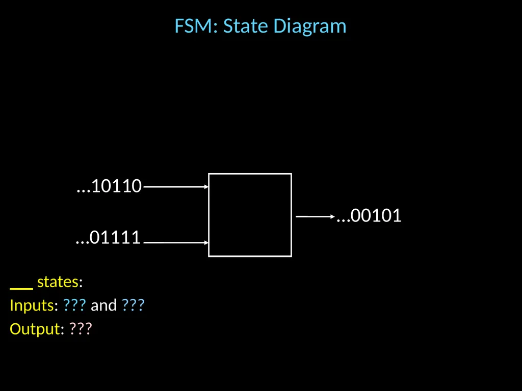
slide16. FSM: State Diagram states:
Inputs: ??? and ???
Output: ???
. …10110 …01111 …00101<br>
slide17. FSM: State Diagram S0 S1 __/_ __/_ __/_ __/_ __/_ __/_ __/_ __/_ …10110 …01111 …00101 states:
Inputs: ??? and ???
Output: ???
.<br>
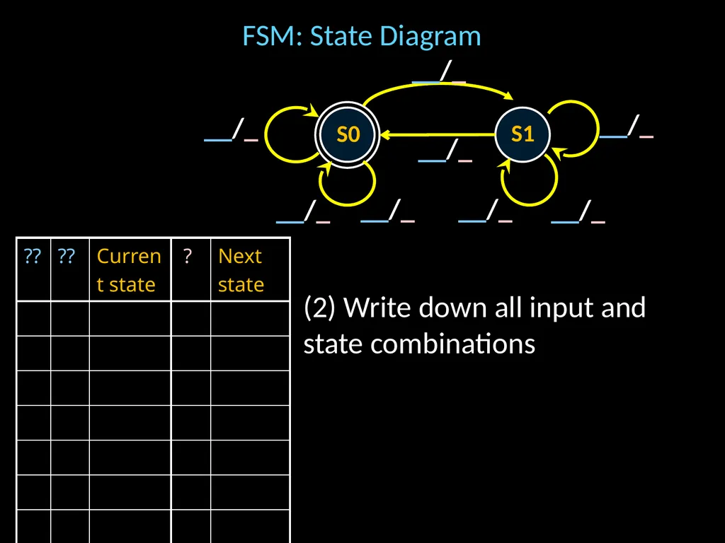
slide18. FSM: State Diagram (2) Write down all input and state combinations S0 S1 __/_ __/_ __/_ __/_ __/_ __/_ __/_ __/_<br>
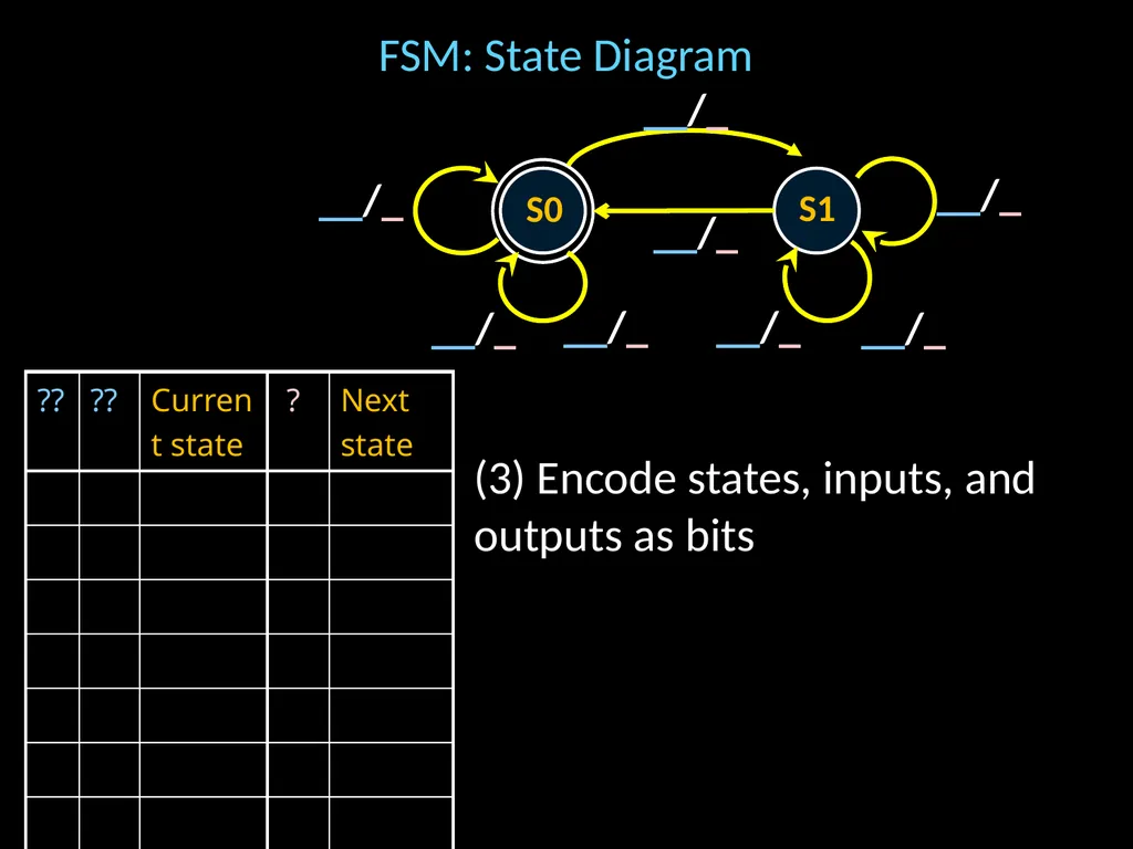
slide19. FSM: State Diagram (3) Encode states, inputs, and outputs as bits S0 S1 __/_ __/_ __/_ __/_ __/_ __/_ __/_ __/_<br>
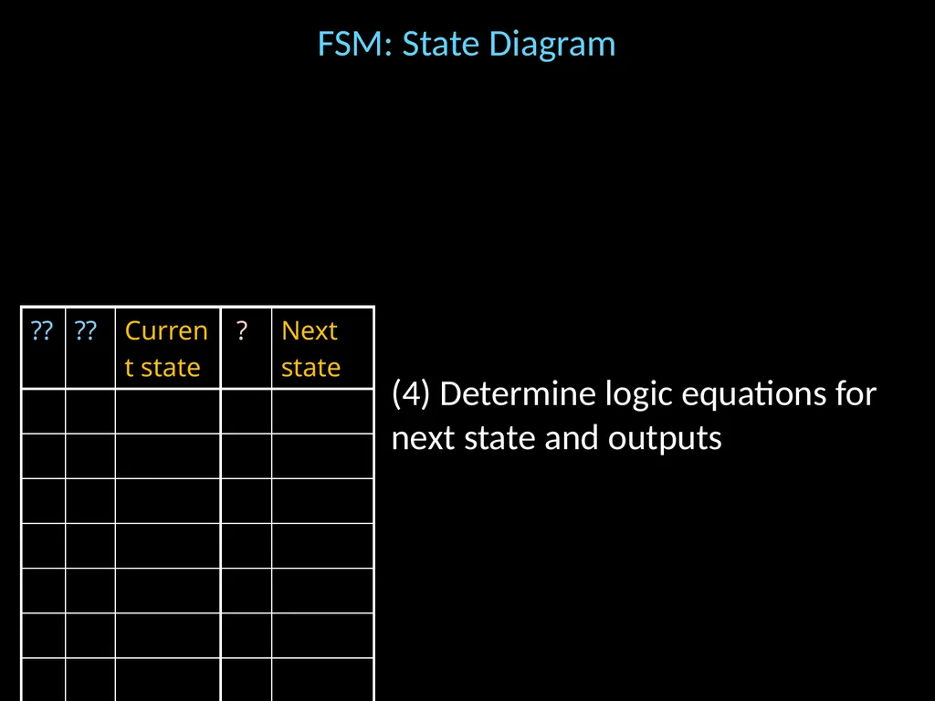
slide20. FSM: State Diagram (4) Determine logic equations for next state and outputs<br>
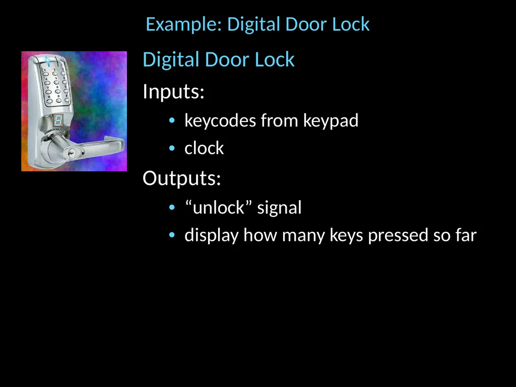
slide21. Example: Digital Door Lock Digital Door Lock
Inputs:
keycodes from keypad
clock
Outputs:
“unlock” signal
display how many keys pressed so far<br>
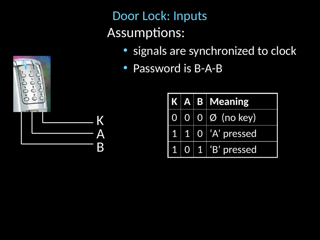
slide22. Door Lock: Inputs Assumptions:
signals are synchronized to clock
Password is B-A-B K A B<br>
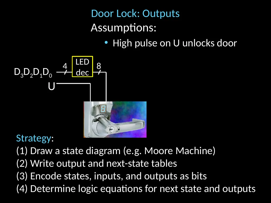
slide23. Door Lock: Outputs Assumptions:
High pulse on U unlocks door U D3D2D1D0 4 LEDdec 8 Strategy:
(1) Draw a state diagram (e.g. Moore Machine)
(2) Write output and next-state tables
(3) Encode states, inputs, and outputs as bits
(4) Determine logic equations for next state and outputs<br>
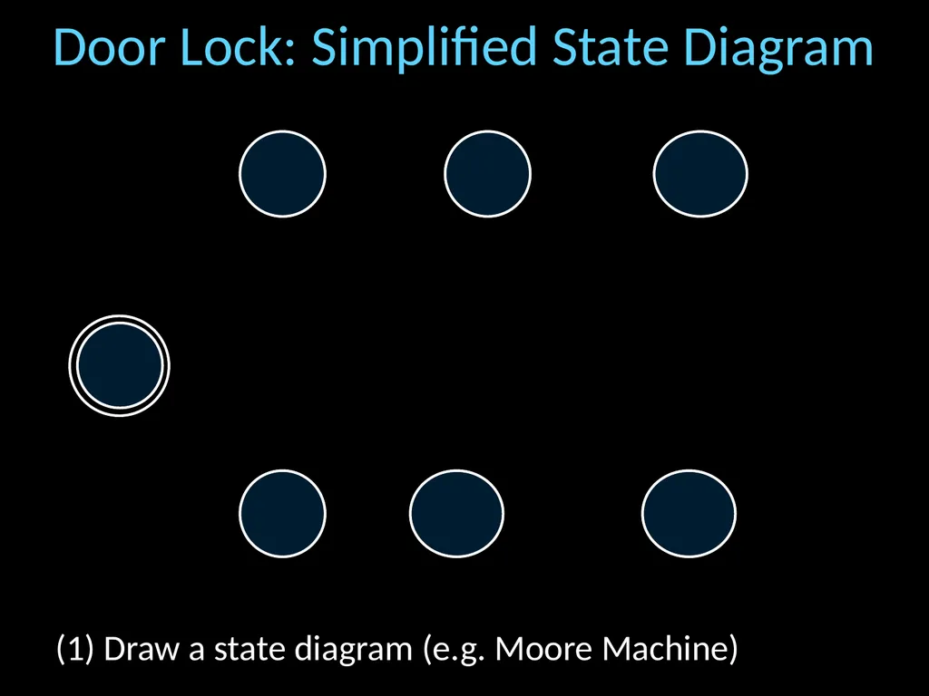
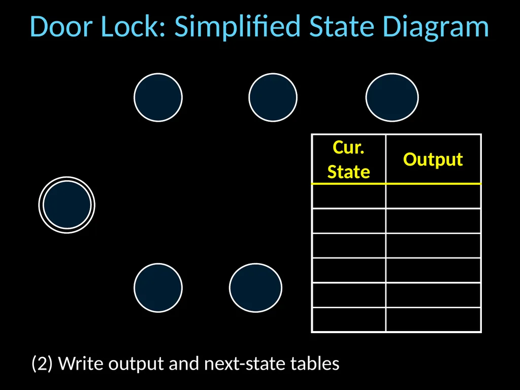
slide24. Door Lock: Simplified State Diagram (1) Draw a state diagram (e.g. Moore Machine)<br>
slide25. Door Lock: Simplified State Diagram any (2) Write output and next-state tables<br>
slide26. Door Lock: Simplified State Diagram G2 G3 ”2” ”3”, U Ø “B” any else (2) Write output and next-state tables<br>
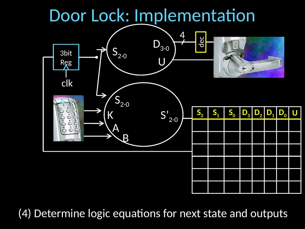
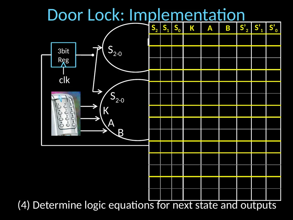
slide27. Door Lock: Implementation 4 dec 3bitReg clk U D3-0 S2-0 S’2-0 S2-0 K A B (4) Determine logic equations for next state and outputs<br>
slide28. Door Lock: Implementation 4 dec 3bitReg clk U D3-0 S2-0 S’2-0 S2-0 K A B (4) Determine logic equations for next state and outputs<br>
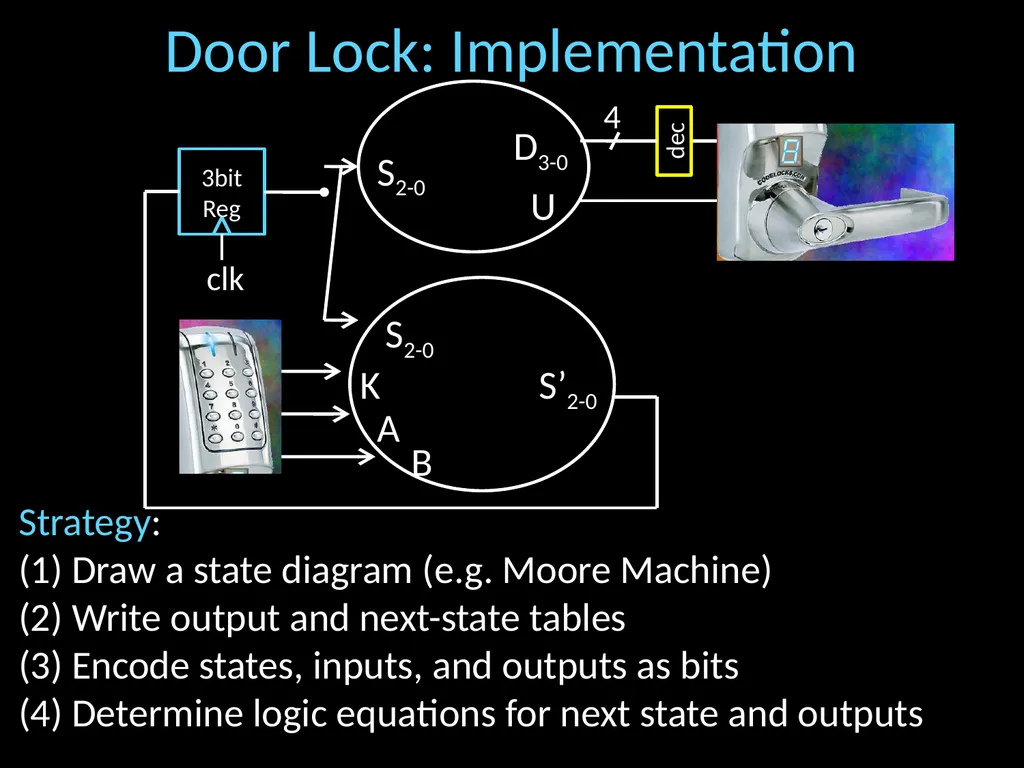
slide29. Door Lock: Implementation 4 dec 3bitReg clk U D3-0 S2-0 S’2-0 S2-0 K A B Strategy:
(1) Draw a state diagram (e.g. Moore Machine)
(2) Write output and next-state tables
(3) Encode states, inputs, and outputs as bits
(4) Determine logic equations for next state and outputs<br>
slide30. Door Lock: Implementation Strategy:
(1) Draw a state diagram (e.g. Moore Machine)
(2) Write output and next-state tables
(3) Encode states, inputs, and outputs as bits
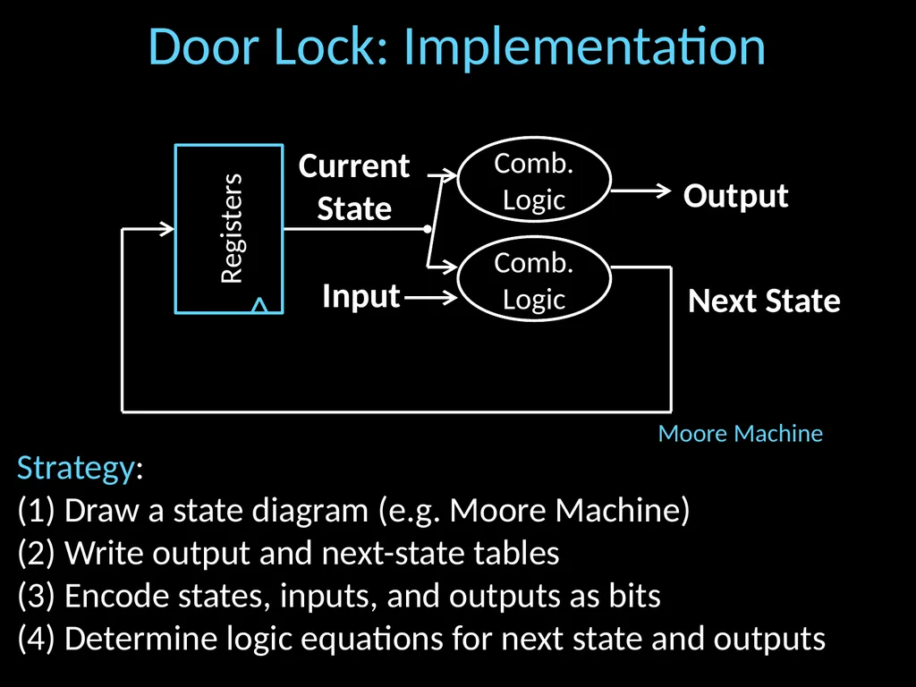
(4) Determine logic equations for next state and outputs Next State Current State Input Output Registers Comb.Logic Comb.Logic Moore Machine<br>
slide31. Goals for today Review
Finite State Machines<br>
slide32. Summary We can now build interesting devices with sensors
Using combinational logic
We can also store data values
Stateful circuit elements (D Flip Flops, Registers, …)
State Machines or Ad-Hoc Circuits<br>

CS 3410
Computer Science
Cornell University The slides are the product of many rounds of teaching CS 3410 by Professors Weatherspoon, Bala, Bracy, and Sirer.<br>
slide2. Goals for Today Finite State Machines (FSM)
How do we design logic circuits with state?
Types of FSMs: Mealy and Moore Machines
Examples: Serial Adder and a Digital Door Lock<br>
slide3. Finite State Machines<br>
slide4. Next Goal How do we design logic circuits with state?<br>
slide5. Finite State Machines An electronic machine which has
external inputs
externally visible outputs
internal state
Output and next state depend on
inputs
current state<br>
slide6. Abstract Model of FSM Machine is
M = ( S, I, O, )
S: Finite set of states
I: Finite set of inputs
O: Finite set of outputs
: State transition function
Next state depends on present input and present state<br>
slide7. Automata Model Finite State Machine
inputs from external world
outputs to external world
internal state
combinational logic Next State Current State Input Output Registers Comb.Logic<br>
slide8. FSM Example Legend state input/output startstate A B C D down/on up/off down/on down/off up/off down/off up/off up/off Input: up or down
Output: on or off
States: A, B, C, or D<br>
slide9. FSM Example Legend state input/output startstate A B C D down/on up/off down/on down/off up/off down/off up/off up/off Input: = up or = down
Output: = on or = off
States: = A, = B, = C, or = D<br>
slide10. FSM Example Legend S1S0 i0i1i2…/o0o1o2… S1S0 00 01 10 11 1/1 0/0 1/1 1/0 0/0 1/0 0/0 0/0 Input: 0=up or 1=down
Output: 1=on or 0=off
States: 00=A, 01=B, 10=C, or 11=D<br>
slide11. General Case: Mealy Machine
Outputs and next state depend on bothcurrent state and input Mealy Machine Next State Current State Input Output Registers Comb.Logic<br>
slide12. Moore Machine Special Case: Moore Machine
Outputs depend only on current state Next State Current State Input Output Registers Comb.Logic Comb.Logic<br>
slide13. Moore Machine FSM Example Legend stateout input startout A off Bon C off D off down up down down up up down up Input: up or down
Output: on or off
States: A, B, C, or D<br>
slide14. Mealy Machine FSM Example Legend state input/output startstate A B C D down/on up/off down/on down/off up/off up/off down/off up/off Input: up or down
Output: on or off
States: A, B, C, or D<br>
slide15. Activity#2: Create a Logic Circuit for a Serial Adder Add two infinite input bit streams
streams are sent with least-significant-bit (lsb) first
How many states are needed to represent FSM?
Draw and Fill in FSM diagram …10110 …01111 …00101 Strategy:
(1) Draw a state diagram (e.g. Mealy Machine)
(2) Write output and next-state tables
(3) Encode states, inputs, and outputs as bits
(4) Determine logic equations for next state and outputs Sum: output<br>
slide16. FSM: State Diagram states:
Inputs: ??? and ???
Output: ???
. …10110 …01111 …00101<br>
slide17. FSM: State Diagram S0 S1 __/_ __/_ __/_ __/_ __/_ __/_ __/_ __/_ …10110 …01111 …00101 states:
Inputs: ??? and ???
Output: ???
.<br>
slide18. FSM: State Diagram (2) Write down all input and state combinations S0 S1 __/_ __/_ __/_ __/_ __/_ __/_ __/_ __/_<br>
slide19. FSM: State Diagram (3) Encode states, inputs, and outputs as bits S0 S1 __/_ __/_ __/_ __/_ __/_ __/_ __/_ __/_<br>
slide20. FSM: State Diagram (4) Determine logic equations for next state and outputs<br>
slide21. Example: Digital Door Lock Digital Door Lock
Inputs:
keycodes from keypad
clock
Outputs:
“unlock” signal
display how many keys pressed so far<br>
slide22. Door Lock: Inputs Assumptions:
signals are synchronized to clock
Password is B-A-B K A B<br>
slide23. Door Lock: Outputs Assumptions:
High pulse on U unlocks door U D3D2D1D0 4 LEDdec 8 Strategy:
(1) Draw a state diagram (e.g. Moore Machine)
(2) Write output and next-state tables
(3) Encode states, inputs, and outputs as bits
(4) Determine logic equations for next state and outputs<br>
slide24. Door Lock: Simplified State Diagram (1) Draw a state diagram (e.g. Moore Machine)<br>
slide25. Door Lock: Simplified State Diagram any (2) Write output and next-state tables<br>
slide26. Door Lock: Simplified State Diagram G2 G3 ”2” ”3”, U Ø “B” any else (2) Write output and next-state tables<br>
slide27. Door Lock: Implementation 4 dec 3bitReg clk U D3-0 S2-0 S’2-0 S2-0 K A B (4) Determine logic equations for next state and outputs<br>
slide28. Door Lock: Implementation 4 dec 3bitReg clk U D3-0 S2-0 S’2-0 S2-0 K A B (4) Determine logic equations for next state and outputs<br>
slide29. Door Lock: Implementation 4 dec 3bitReg clk U D3-0 S2-0 S’2-0 S2-0 K A B Strategy:
(1) Draw a state diagram (e.g. Moore Machine)
(2) Write output and next-state tables
(3) Encode states, inputs, and outputs as bits
(4) Determine logic equations for next state and outputs<br>
slide30. Door Lock: Implementation Strategy:
(1) Draw a state diagram (e.g. Moore Machine)
(2) Write output and next-state tables
(3) Encode states, inputs, and outputs as bits
(4) Determine logic equations for next state and outputs Next State Current State Input Output Registers Comb.Logic Comb.Logic Moore Machine<br>
slide31. Goals for today Review
Finite State Machines<br>
slide32. Summary We can now build interesting devices with sensors
Using combinational logic
We can also store data values
Stateful circuit elements (D Flip Flops, Registers, …)
State Machines or Ad-Hoc Circuits<br>