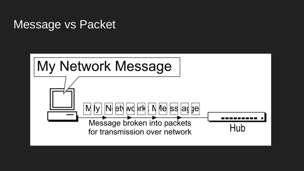
04
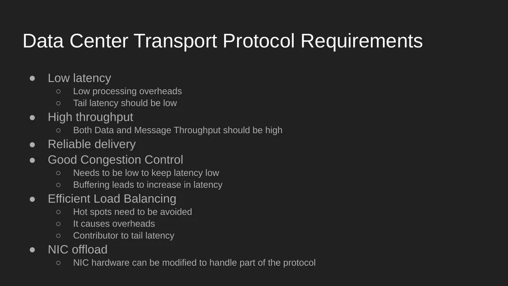
Data Center Transport Protocol Requirements Low latency
Low processing overheads
Tail latency should be low
High throughput
Both Data and Message Throughput should be high
Reliable delivery
Good Congestion Control
Needs to be low to keep latency low
Buffering leads to increase in latency
Efficient Load Balancing
Hot spots need to be avoided
It causes overheads
Contributor to tail latency
NIC offload
NIC hardware can be modified to handle part of the protocol<br>
06
Problems with TCP in the Data Center Stream orientation
Connection orientation
Bandwidth sharing (Fair Scheduling)
Sender-driven Congestion Control
In-order packet delivery<br>
07
TCP Problem: Stream Orientation TCP only aware of current packet length, not message size
TCP just breaks up data into ‘MSS bytes’ and sends
Causes Buffering and Packet Re-ordering at receiver
Receiver has no knowledge of how much data it is going to receive and when to start processing
Sender responsible for Congestion and Flow Control
TCP Head of Line Blocking (HoLB) problem
Multiple TCP connections from the sender to counter this causes connection explosion issue
Load Balancing difficulties due to Flow-Consistent Routing and hot spots<br>
08
TCP Problem: Connection Orientation Connections cause overheads in terms of storage and processing time
Connection setup takes up 1 RTT
For TCP, keeping packet buffers and application level state aside, 2000 bytes of state data maintained per connection in Linux<br>
09
TCP Problem: Bandwidth Sharing TCP uses Fair Scheduling
TCP HoLB causes short messages to have high RTTs
Under high load, all streams share bandwidth, which collectively slows down everyone<br>
10
TCP Problem: Sender-Driven Congestion Control Congestion detected (assumed) through dropped packets or duplicate ACKs
Not the most accurate parameters
ECN helps in congestion detection, but is a late indicator
Congestion implies buffer occupancy and queueing
Increases latency
Causes HoLB
Doesn’t make use of priority queues in modern switches
Sender responsible for managing congestion, when receiver is more aware of its state<br>
11
TCP Problem: In-Order Packet Delivery Flow-Consistent Routing
Doesn’t allow Packet Spraying
Load Balancing issues increase tail latency
Causes hot spot links
Causes hot spot cores
Not tolerant to high levels of re-ordering<br>
12
Recap: Problems with TCP in the Data Center Stream orientation
Connection orientation
Bandwidth sharing (Fair Scheduling)
Sender-driven Congestion Control
In-order packet delivery<br>
13
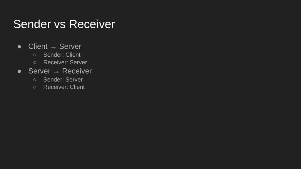
Sender vs Receiver Client → Server
Sender: Client
Receiver: Server
Server → Receiver
Sender: Server
Receiver: Client<br>
14
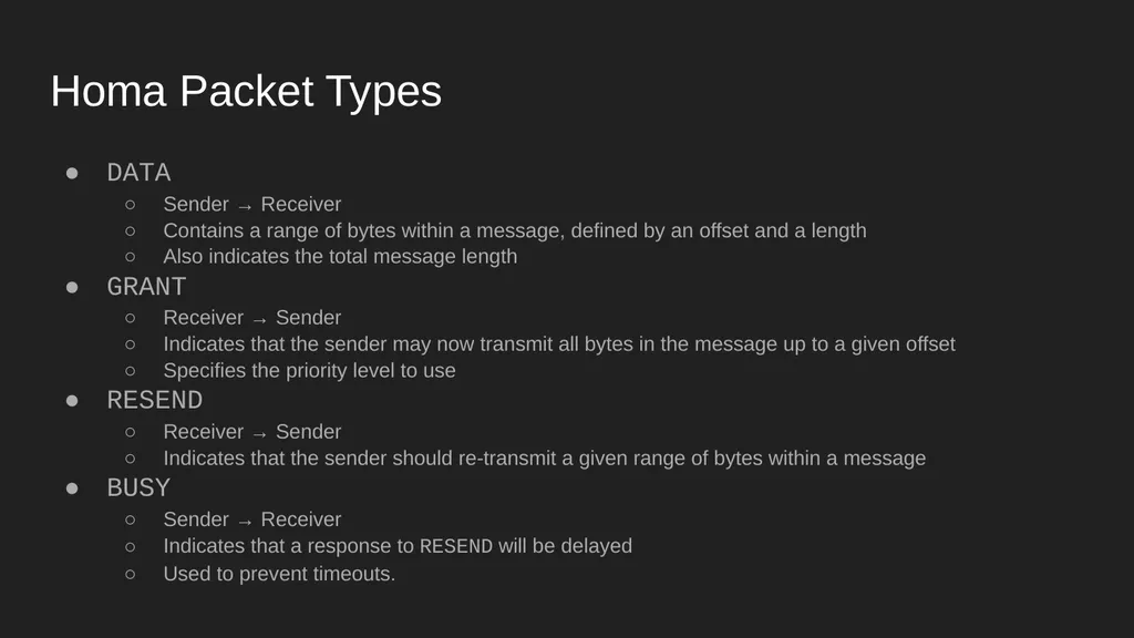
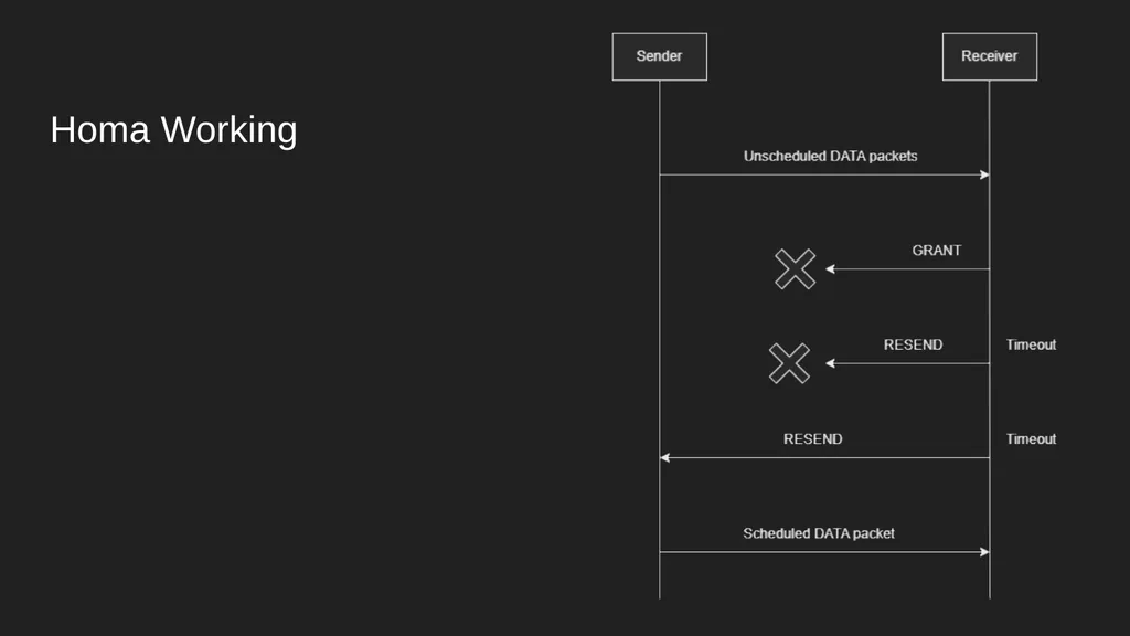
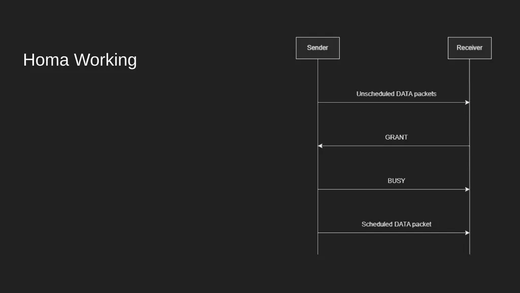
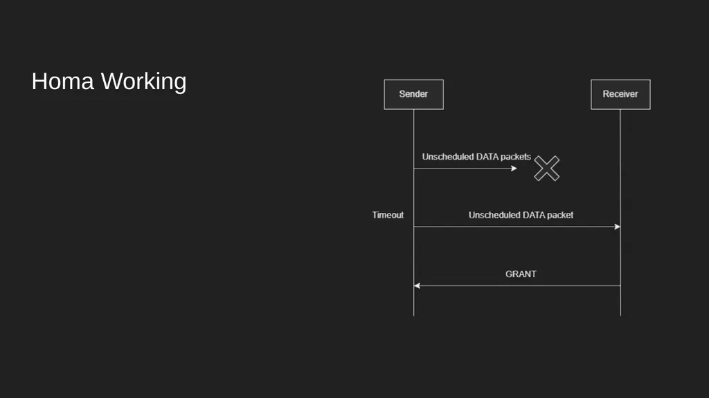
Homa Packet Types DATA
Sender → Receiver
Contains a range of bytes within a message, defined by an offset and a length
Also indicates the total message length
GRANT
Receiver → Sender
Indicates that the sender may now transmit all bytes in the message up to a given offset
Specifies the priority level to use
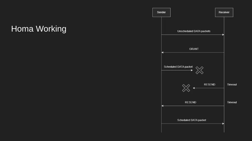
RESEND
Receiver → Sender
Indicates that the sender should re-transmit a given range of bytes within a message
BUSY
Sender → Receiver
Indicates that a response to RESEND will be delayed
Used to prevent timeouts.<br>
15
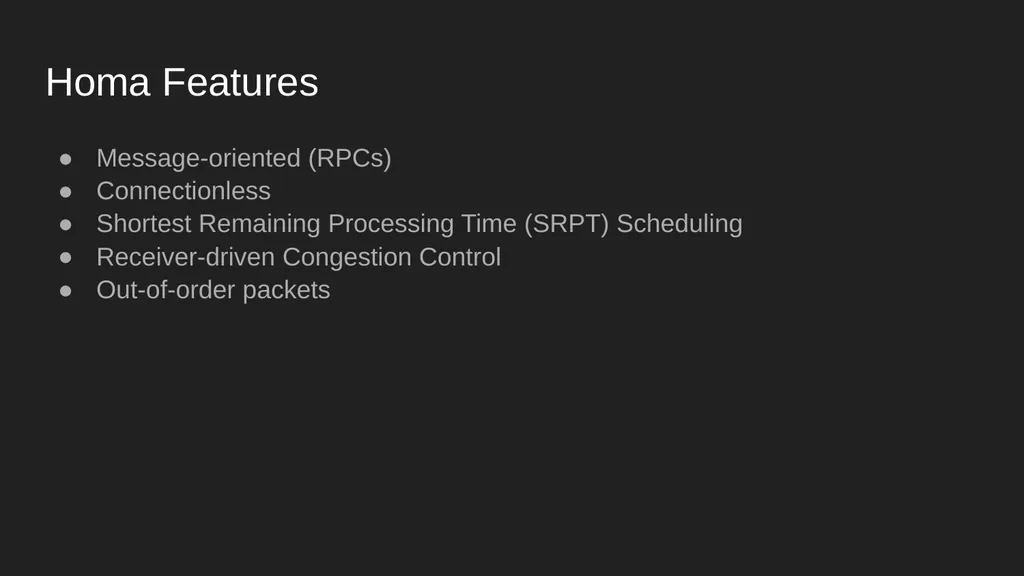
Homa Features Message-oriented (RPCs)
Connectionless
Shortest Remaining Processing Time (SRPT) Scheduling
Receiver-driven Congestion Control
Out-of-order packets<br>
16
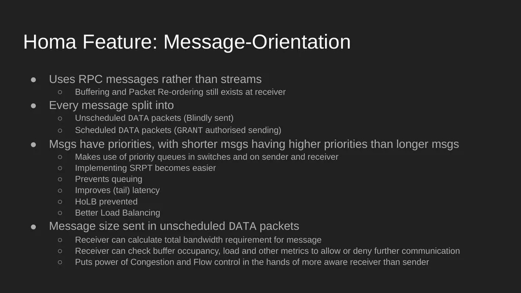
Homa Feature: Message-Orientation Uses RPC messages rather than streams
Buffering and Packet Re-ordering still exists at receiver
Every message split into
Unscheduled DATA packets (Blindly sent)
Scheduled DATA packets (GRANT authorised sending)
Msgs have priorities, with shorter msgs having higher priorities than longer msgs
Makes use of priority queues in switches and on sender and receiver
Implementing SRPT becomes easier
Prevents queuing
Improves (tail) latency
HoLB prevented
Better Load Balancing
Message size sent in unscheduled DATA packets
Receiver can calculate total bandwidth requirement for message
Receiver can check buffer occupancy, load and other metrics to allow or deny further communication
Puts power of Congestion and Flow control in the hands of more aware receiver than sender<br>
17
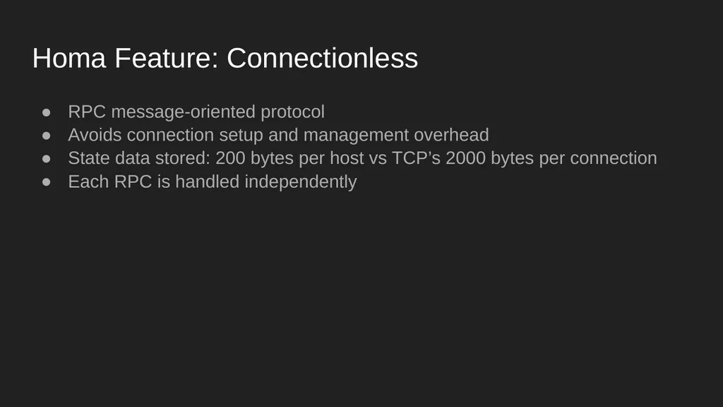
Homa Feature: Connectionless RPC message-oriented protocol
Avoids connection setup and management overhead
State data stored: 200 bytes per host vs TCP’s 2000 bytes per connection
Each RPC is handled independently<br>
18
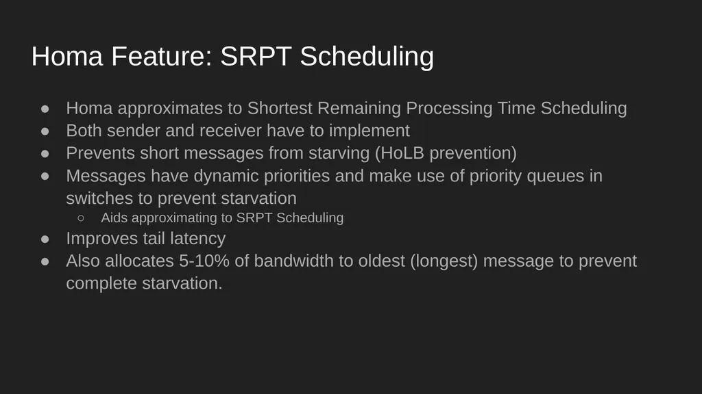
Homa Feature: SRPT Scheduling Homa approximates to Shortest Remaining Processing Time Scheduling
Both sender and receiver have to implement
Prevents short messages from starving (HoLB prevention)
Messages have dynamic priorities and make use of priority queues in switches to prevent starvation
Aids approximating to SRPT Scheduling
Improves tail latency
Also allocates 5-10% of bandwidth to oldest (longest) message to prevent complete starvation.<br>
19
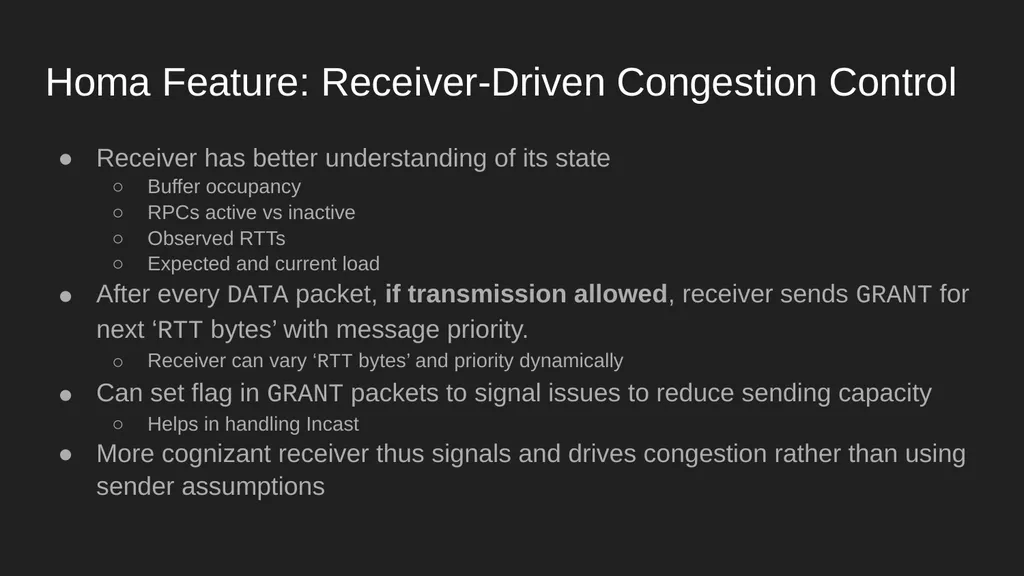
Homa Feature: Receiver-Driven Congestion Control Receiver has better understanding of its state
Buffer occupancy
RPCs active vs inactive
Observed RTTs
Expected and current load
After every DATA packet, if transmission allowed, receiver sends GRANT for next ‘RTT bytes’ with message priority.
Receiver can vary ‘RTT bytes’ and priority dynamically
Can set flag in GRANT packets to signal issues to reduce sending capacity
Helps in handling Incast
More cognizant receiver thus signals and drives congestion rather than using sender assumptions<br>
20
Homa Feature: Out-of-Order Packets High tolerance threshold for out-of-order packets
Aids Packet Spraying, which reduces latency, hot spots and buffering<br>
21
Recap: Homa Features Message-oriented (RPCs)
Connectionless
Shortest Remaining Processing Time (SRPT) Scheduling
Receiver-driven Congestion Control
Out-of-order packets<br>
22
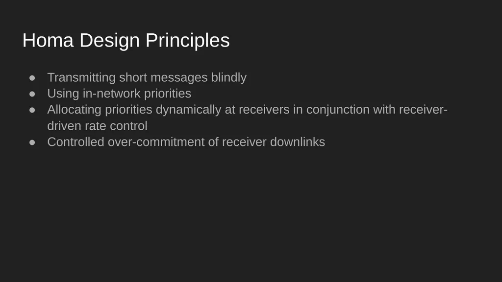
Homa Design Principles Transmitting short messages blindly
Using in-network priorities
Allocating priorities dynamically at receivers in conjunction with receiver-driven rate control
Controlled over-commitment of receiver downlinks<br>
23
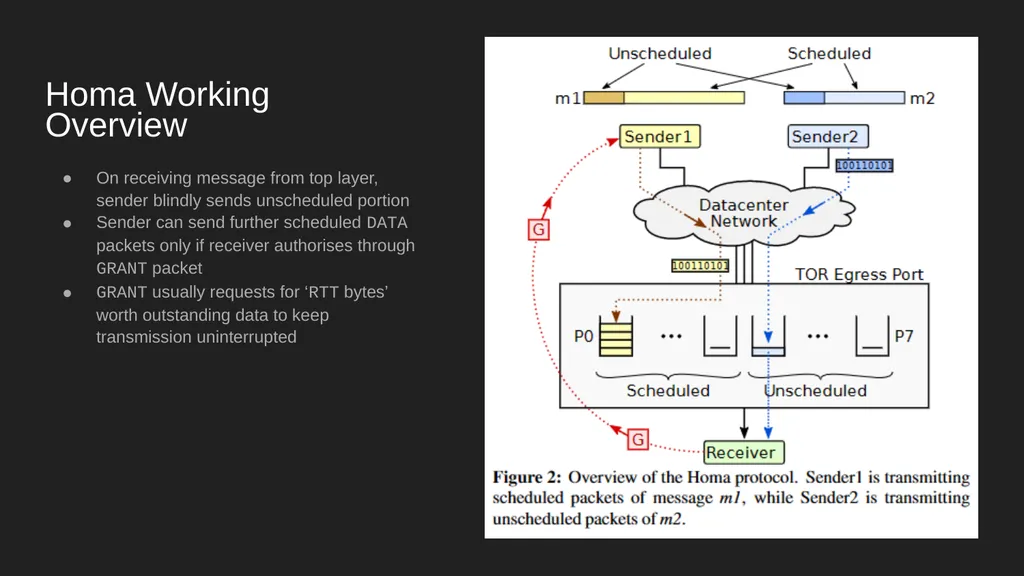
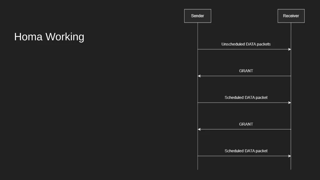
Homa Working Overview On receiving message from top layer, sender blindly sends unscheduled portion
Sender can send further scheduled DATA packets only if receiver authorises through GRANT packet
GRANT usually requests for ‘RTT bytes’ worth outstanding data to keep transmission uninterrupted<br>
29
Homa Assumptions / Limitations Designed for Data Center environments; won’t work well in WANs
Assumes that congestion occurs primarily at host downlinks (ToR switches), not in core of network, due to Data Center designs
Congestion and buffer occupancy reducing mechanisms might make congestion lesser than TCP flows, but left open for future work.
One Homa implementation per physical NIC recommended
Virtualizing NICs and sharing Homa state between them on one physical NIC left for future work.
With faster networks, ‘RTT bytes’ might increase, thus causing buffer occupancy issues and reducing Incast tolerance
Incast above a certain threshold will cause packet loss and degraded perf<br>
30
Tentative Future Plan Understand:
Homa Linux Implementation
Existing performance comparisons
DCTCP
Carry out performance experiments
Try to look into future work
Try to plan and execute experiments along those lines
Try to find improvements to protocol
Try to explore future work<br>
31
Resources networking.harshkapadia.me/homa<br>