
Hyperinflation Therapy CHAPTER 13 Objectives
Description: Hyperinflation Therapy CHAPTER 13 Objectives Incentive spirometry Intermittent positive-pressure breathing Intrapulmonary percussive ventilation Positive airway pressure adjuncts Introduction (1 of 2) Hyperinflation therapy (HT) is also
Related Topics
Download Presentation
"Hyperinflation Therapy CHAPTER 13 Objectives" is the property of its rightful owner. Permission is granted to download and print the materials on this website for personal, non-commercial use only, and to display it on your personal computer provided you do not modify the materials and that you retain all copyright notices contained in the materials. By downloading content from our website, you accept the terms of this agreement.
Presentation Transcript
slide1. Hyperinflation Therapy CHAPTER 13<br>
slide2. Objectives Incentive spirometry
Intermittent positive-pressure breathing
Intrapulmonary percussive ventilation
Positive airway pressure adjuncts<br>
slide3. Introduction (1 of 2) Hyperinflation therapy (HT) is also known as lung expansion maneuvers
Subjects the lungs to volumes greater than normal to reinflate collapsed areas and improve gas exchange
Used to prevent/treat atelectasis
The treatment of atelectasis is dependent on its underlying origin and pathophysiology<br>
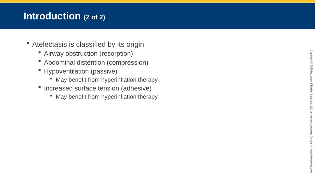
slide4. Introduction (2 of 2) Atelectasis is classified by its origin
Airway obstruction (resorption)
Abdominal distention (compression)
Hypoventilation (passive)
May benefit from hyperinflation therapy
Increased surface tension (adhesive)
May benefit from hyperinflation therapy<br>
slide5. Incentive Spirometer (IS) (1 of 10) A low-level resistance breathing exercise
Incorporates sustained maximal inspiration (SMI)
The equivalent of a deep breath or sigh that is routinely generated by a spontaneous yawn
Goal-oriented device that use visual aids such as raising a lightweight ball or indicator to gauge progress toward goal attainment
Devices are either flow or volume oriented<br>
slide6. Incentive Spirometer (IS) (2 of 10) Clinical outcomes are based on repetition of deep breaths that results in airway patency and in turn treats the underlying cause of the atelectasis
Evidence of lung expansion including observation of chest rise and confirmation of lung volume achieved is greater using a volume-oriented compared to a flow-oriented devices<br>
slide7. Incentive Spirometer (IS) (3 of 10) Application
Adjunct for deep breathing across the care continuum
Inspiratory breath-holding for at least 3 to 10 seconds followed by passive exhalation
Postoperative reversal of atelectasis
Mild restrictive diseases affected by abnormal diaphragm function
Management of atelectasis in sickle cell disease and prevention of complications associated with acute chest syndrome<br>
slide8. Incentive Spirometer (IS) (4 of 10) Application
IS therapy is not completely benign
May induce hyperventilation
Hypoxia may occur if supplemental oxygen therapy is interrupted while the patient performs the maneuver
Patients may experience weakness or fatigue
Discomfort related to incisional or procedural pain may occur
Patients at risk for air leak or those who present with underlying obstructive lung disease may be at risk for bronchospasm (asthma) or barotrauma (emphysema)
Patients with COPD may have air-trapping and hyperinflation<br>
slide9. Incentive Spirometer (IS) (5 of 10) Application
Should not be used with:
Unconscious patients
Patients with no cognitive abilities
Those unable to reproduce the maneuver because of significant reduction in pulmonary mechanics
Vital capacity less than 10 mL/kg
Inspiratory capacity less than one-third predicted normal
Care should be taken to monitor patients and assure an understanding of how to perform the technique properly<br>
slide10. Incentive Spirometer (IS) (6 of 10) Principles of operation
Volume-oriented
Integrate concept of true and precise volume displacement
During inspiration, the device’s indicator rises concomitantly with the change in volume
Diaphragmatic motion is increased when using a volume-oriented spirometer compared to its flow-oriented counterpart<br>
slide11. Incentive Spirometer (IS) (7 of 10) Principles of operation
Flow-oriented
Directly measures flow
Volume is calculated based on flow measurements and times
The rise of one ball (or more) indicates the flow generated
A rise in flow is an indirect indicator that the volume has increased
Beneficial effect is related to the performance of SMI
Flow is measured in mL/sec and operational ranges vary among devices<br>
slide12. Incentive Spirometer (IS) (8 of 10) Currently available devices
Volume-oriented
Voldyne exercisers
Three sizes including a pediatric size
The Coach 2
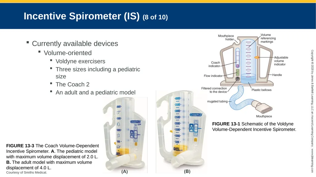
An adult and a pediatric model FIGURE 13-1 Schematic of the Voldyne Volume-Dependent Incentive Spirometer. FIGURE 13-3 The Coach Volume-Dependent Incentive Spirometer. A. The pediatric model with maximum volume displacement of 2.0 L. B. The adult model with maximum volume displacement of 4.0 L.
Courtesy of Smiths Medical.<br>
slide13. Incentive Spirometer (IS) (9 of 10) Currently available devices
Flow-oriented
Clini-Flow
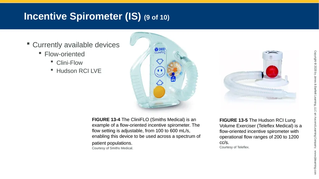
Hudson RCI LVE FIGURE 13-4 The CliniFLO (Smiths Medical) is an example of a flow-oriented incentive spirometer. The flow setting is adjustable, from 100 to 600 mL/s, enabling this device to be used across a spectrum of patient populations.
Courtesy of Smiths Medical. FIGURE 13-5 The Hudson RCI Lung Volume Exerciser (Teleflex Medical) is a flow-oriented incentive spirometer with operational flow ranges of 200 to 1200 cc/s.
Courtesy of Teleflex.<br>
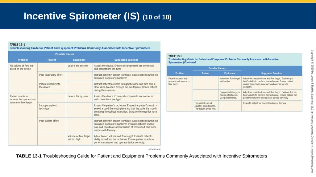
slide14. Incentive Spirometer (IS) (10 of 10) TABLE 13-1 Troubleshooting Guide for Patient and Equipment Problems Commonly Associated with Incentive Spirometers<br>
slide15. Intermittent Positive Pressure Breathing (IPPB) (1 of 12) Utilizes a mechanical positive pressure device
Delivers a controlled airflow into the lungs at a predetermined pressure when triggered by spontaneous breathing activities
Can be flow, pressure, or time cycled
Delivered by a stand-alone positive pressure device or through an invasive or noninvasive ventilator<br>
slide16. Intermittent Positive Pressure Breathing (IPPB) (2 of 12) Application
Inpatient, outpatient, and in-home settings
Can be used on patients with cognitive limitations
Variety of interfaces (e.g., mouthpiece, mask, mouth shield, or direct connection to an artificial airway)
Brief treatment length (20 to minutes)
Patients seated in semi-Fowler<br>
slide17. Intermittent Positive Pressure Breathing (IPPB) (3 of 12) Application
Settings
P = 10–15 cm H2O (initially)
IE = 13
Trigger threshold set to reduce the patient’s inspiratory work and minimize risk of auto-triggering
Inspiratory pressure is then slowly increased until a minimum delivered volume of at least one-third of the patient’s inspiratory capacity is achieved<br>
slide18. Intermittent Positive Pressure Breathing (IPPB) (4 of 12) Application
Used to treat postoperative atelectasis
Untreated chest pneumothorax is an absolute contraindication
Relative contraindications include hemodynamic instability, blebs, recent facial, oral, skull, or esophageal surgeries, TE fistula, and nausea
Hazards and complications include, but are not limited to, gastric distension, nosocomial infection, hypoxemia, hypocarbia, hemoptysis, decreased venous return, air trapping, and barotrauma<br>
slide19. Intermittent Positive Pressure Breathing (IPPB) (5 of 12) Principles of operation
Setting of a PIP, PEEP during PCV on a noninvasive ventilator
Appropriate interface should be selected
Pressure or flow triggered
Flow is variable upon patient demand
PSV can also be used to deliver IPPB<br>
slide20. Intermittent Positive Pressure Breathing (IPPB) (6 of 12) Principles of operation
IPPB can be delivered with
Electrically or pneumatically powered devices
Hybrid flow devices<br>
slide21. Intermittent Positive Pressure Breathing (IPPB) (7 of 12) Currently available devices
Puritan Bennett AP-5
Electrically powered
Bird Mark 7
Pneumatically powered
Vortran IPPB
Pneumatically powered hybrid device<br>
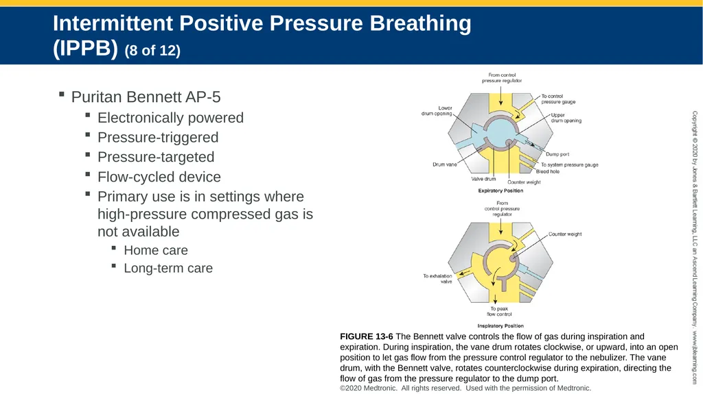
slide22. Intermittent Positive Pressure Breathing (IPPB) (8 of 12) Puritan Bennett AP-5
Electronically powered
Pressure-triggered
Pressure-targeted
Flow-cycled device
Primary use is in settings where high-pressure compressed gas is not available
Home care
Long-term care FIGURE 13-6 The Bennett valve controls the flow of gas during inspiration and expiration. During inspiration, the vane drum rotates clockwise, or upward, into an open position to let gas flow from the pressure control regulator to the nebulizer. The vane drum, with the Bennett valve, rotates counterclockwise during expiration, directing the flow of gas from the pressure regulator to the dump port.
©2020 Medtronic. All rights reserved. Used with the permission of Medtronic.<br>
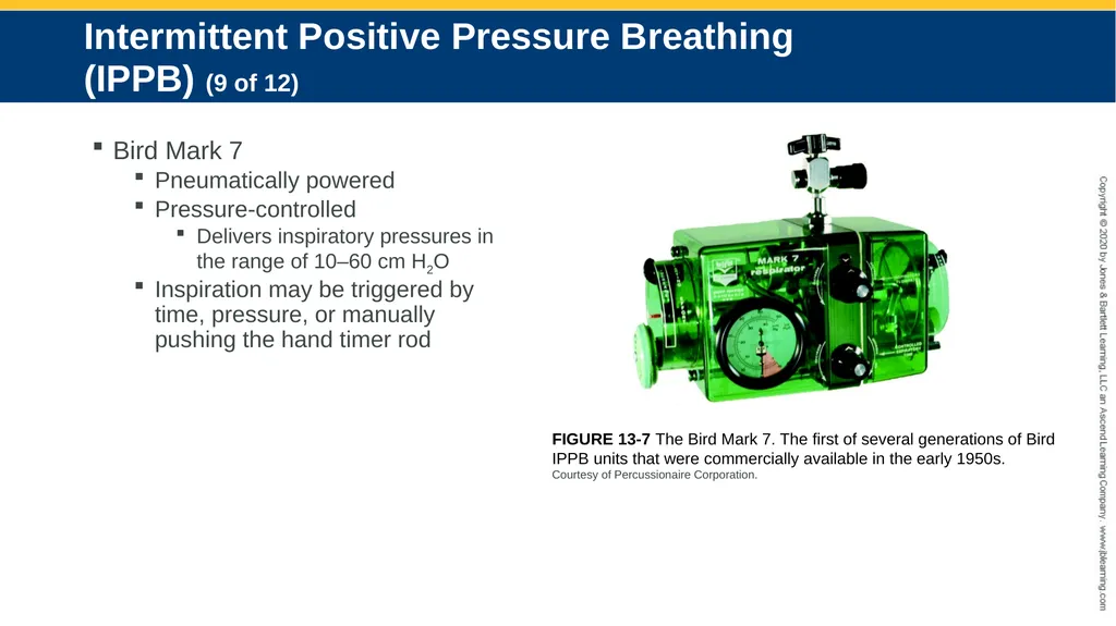
slide23. Intermittent Positive Pressure Breathing (IPPB) (9 of 12) Bird Mark 7
Pneumatically powered
Pressure-controlled
Delivers inspiratory pressures in the range of 10–60 cm H2O
Inspiration may be triggered by time, pressure, or manually pushing the hand timer rod FIGURE 13-7 The Bird Mark 7. The first of several generations of Bird IPPB units that were commercially available in the early 1950s.
Courtesy of Percussionaire Corporation.<br>
slide24. Intermittent Positive Pressure Breathing (IPPB) (10 of 12) Bird Mark 7
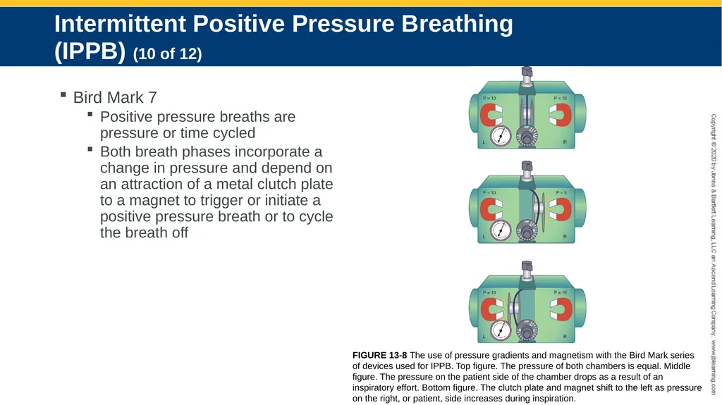
Positive pressure breaths are pressure or time cycled
Both breath phases incorporate a change in pressure and depend on an attraction of a metal clutch plate to a magnet to trigger or initiate a positive pressure breath or to cycle the breath off FIGURE 13-8 The use of pressure gradients and magnetism with the Bird Mark series of devices used for IPPB. Top figure. The pressure of both chambers is equal. Middle figure. The pressure on the patient side of the chamber drops as a result of an inspiratory effort. Bottom figure. The clutch plate and magnet shift to the left as pressure on the right, or patient, side increases during inspiration.<br>
slide25. Intermittent Positive Pressure Breathing (IPPB) (11 of 12) Voltran IPPB
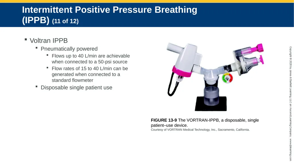
Pneumatically powered
Flows up to 40 L/min are achievable when connected to a 50-psi source
Flow rates of 15 to 40 L/min can be generated when connected to a standard flowmeter
Disposable single patient use FIGURE 13-9 The VORTRAN-IPPB, a disposable, single patient–use device.
Courtesy of VORTRAN Medical Technology, Inc., Sacramento, California.<br>
slide26. Intermittent Positive Pressure Breathing (IPPB) (12 of 12) Voltran IPPB
The modulator is an adjustable spring-loaded valve
Can provide inspiratory pressures from 20 to 50 cm H2O and baseline pressures of PEEP from 2 to 5 cm H2O
The aerosol generator operates from a demand valve
This air entrainment valve allows the patient to access fresh gas, which is drawn in through the nebulizer, if needed
The nebulizer reservoir can hold up to 20 mL of an aqueous solution
Inspiratory time and breath rate are adjustable from 0.5 to 3.0 seconds and 8 to 20 breaths per minute<br>
slide27. Hybrid IPPB/PEP Device (1 of 4) EzPAP
Generate positive airway pressure on inspiration and positive expiratory pressure (PEP)
Enhances collateral ventilation in the airway with back pressure
Medicated aerosol therapy can be delivered in conjunction
Nebulizer does not alter pressure delivery
Device will obstruct the aerosol pathway
May significantly reduce aerosol particle size and patient dose<br>
slide28. Hybrid IPPB/PEP Device (2 of 4) EzPAP
Principles of operation
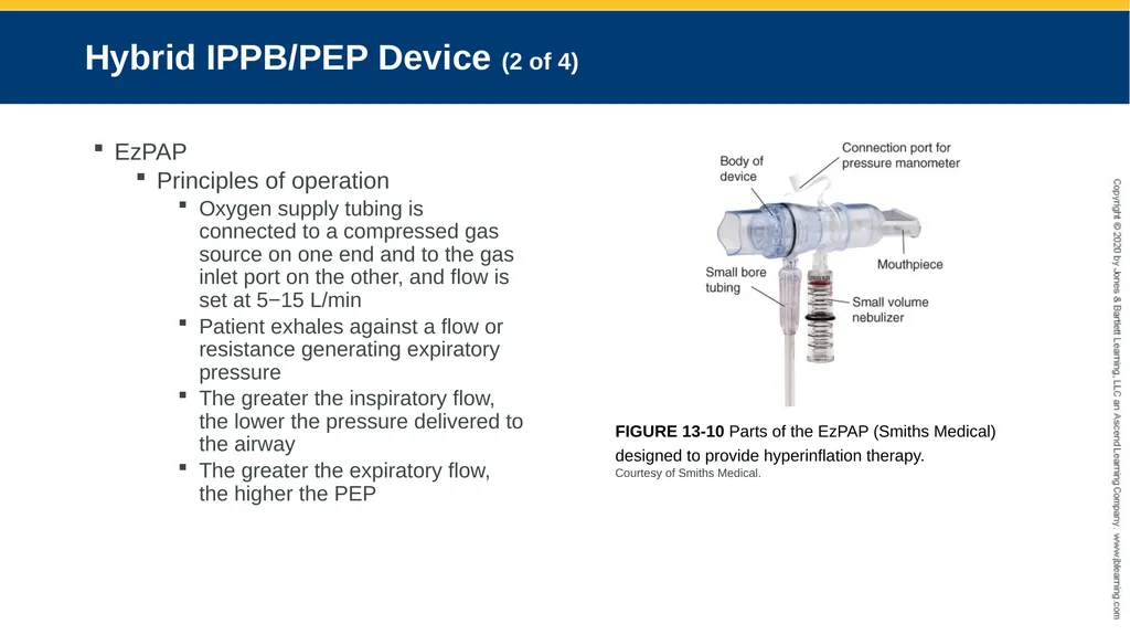
Oxygen supply tubing is connected to a compressed gas source on one end and to the gas inlet port on the other, and flow is set at 5−15 L/min
Patient exhales against a flow or resistance generating expiratory pressure
The greater the inspiratory flow, the lower the pressure delivered to the airway
The greater the expiratory flow, the higher the PEP FIGURE 13-10 Parts of the EzPAP (Smiths Medical) designed to provide hyperinflation therapy.
Courtesy of Smiths Medical.<br>
slide29. Hybrid IPPB/PEP Device (3 of 4) AccuPap
Generates positive airway pressure on inspiration and positive expiratory pressure (PEP)
Incorporates a variable orifice threshold resistor to impede exhaled flow and generate PEP
The patient inspires through the device and exhales against a resistance, generating a positive expiratory pressure
Medicated aerosol therapy can be delivered in conjunction<br>
slide30. Hybrid IPPB/PEP Device (4 of 4) AccuPap
Principles of operation
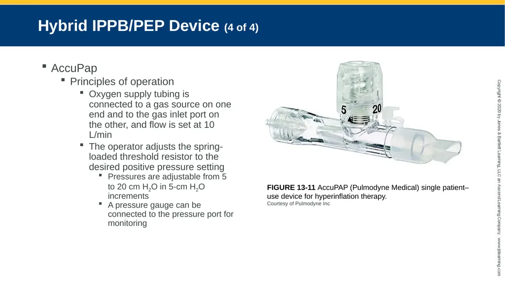
Oxygen supply tubing is connected to a gas source on one end and to the gas inlet port on the other, and flow is set at 10 L/min
The operator adjusts the spring- loaded threshold resistor to the desired positive pressure setting
Pressures are adjustable from 5 to 20 cm H2O in 5-cm H2O increments
A pressure gauge can be connected to the pressure port for monitoring FIGURE 13-11 AccuPAP (Pulmodyne Medical) single patient–
use device for hyperinflation therapy.
Courtesy of Pulmodyne Inc<br>
slide31. Intrapulmonary Percussive Ventilation (IPV) (1 of 26) Combines hyperinflation therapy and airway clearance therapy
Application of high-frequency pulses (100−300/min) superimposed on the patient’s spontaneous breathing pattern
Causes changes in transrespiratory pressure and facilitates the cephalad movement of secretions during passive exhalation<br>
slide32. Intrapulmonary Percussive Ventilation (IPV) (2 of 26) Convective flow, molecular diffusion, Taylor dispersion, and step-by-step inflation are integrated into IPV
Promotes alveolar gas mixing
Augments gas exchange
Enhances airway clearance
Stabilizes mean airway pressure (MAP) while increasing lung volume at a preset pressure<br>
slide33. Intrapulmonary Percussive Ventilation (IPV) (3 of 26) Application
Deliver aerosolized bronchodilators to patients with COPD
Expand collapsed alveoli
Treat atelectasis
Facilitate the secretion mobilization and removal
Neurodegenerative diseases
Cystic fibrosis
Inhalation injuries<br>
slide34. Intrapulmonary Percussive Ventilation (IPV) (4 of 26) Application
Percussive breaths can be manually or automatically triggered
Inpatient and outpatient settings
Applied
Noninvasively
Mask
Mouthpiece
Invasively
Inline with a ventilator circuit<br>
slide35. Intrapulmonary Percussive Ventilation (IPV) (5 of 26) Application
Absolute contraindication
Untreated tension pneumothorax
Relative contraindications
Increased intracranial pressure
TE fistula
Hemodynamic instability
Active hemoptysis
Nausea
Recent facial, oral, or cranial surgery
Untreated TB<br>
slide36. Intrapulmonary Percussive Ventilation (IPV) (6 of 26) Application
Potential hazards
Gastric insufflation
Hyperventilation
Hemodynamic compromise
Air leak
Pneumothorax
Air trapping
Alveolar overdistention<br>
slide37. Intrapulmonary Percussive Ventilation (IPV) (7 of 26) Application
To minimize the occurrence of vomiting and risk of aspiration, precautions should be taken to coordinate a patient’s meals or feeding schedule with therapy
Schedule treatments at least 1 hour after eating
Temporarily discontinue intermittent or continuous enteral nutrition by artificial means using gastrostomy or nasogastric tube feedings during treatment<br>
slide38. Intrapulmonary Percussive Ventilation (IPV) (8 of 26) Currently available devices
Percussionator IPV-1C
Four operator controls
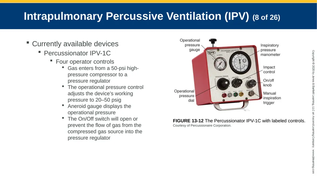
Gas enters from a 50-psi high-pressure compressor to a pressure regulator
The operational pressure control adjusts the device’s working pressure to 20–50 psig
Aneroid gauge displays the operational pressure
The On/Off switch will open or prevent the flow of gas from the compressed gas source into the pressure regulator FIGURE 13-12 The Percussionator IPV-1C with labeled controls.
Courtesy of Percussionaire Corporation.<br>
slide39. Intrapulmonary Percussive Ventilation (IPV) (9 of 26) Currently available devices
Percussionator IPV-1C
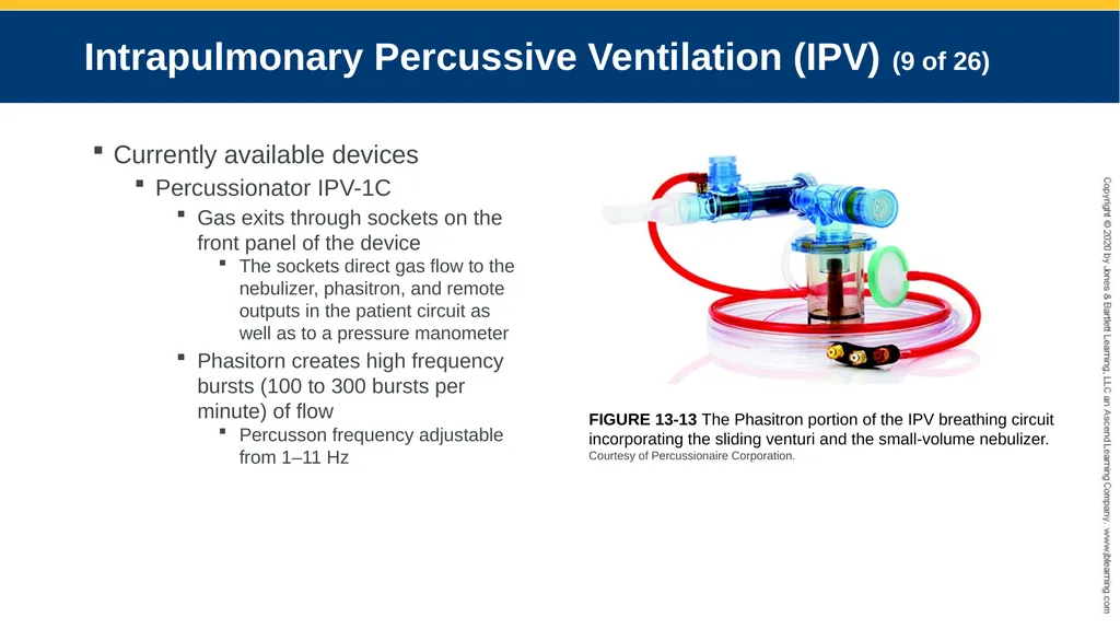
Gas exits through sockets on the front panel of the device
The sockets direct gas flow to the nebulizer, phasitron, and remote outputs in the patient circuit as well as to a pressure manometer
Phasitorn creates high frequency bursts (100 to 300 bursts per minute) of flow
Percusson frequency adjustable from 1–11 Hz FIGURE 13-13 The Phasitron portion of the IPV breathing circuit incorporating the sliding venturi and the small-volume nebulizer.
Courtesy of Percussionaire Corporation.<br>
slide40. Intrapulmonary Percussive Ventilation (IPV) (10 of 26) Currently available devices
Percussionator IPV-1C
Percussion frequency and pressure amplitude are inversely related
As the frequency is increased pressure amplitude decreases
A fixed inspiratory to expiratory (IE) ratio of 12 to 12.5 is typically used
A button is available on the front panel to allow inspiration to be manually triggered
The unit will remain in the inspiratory phase as long as this button is depressed
Manual releasing of this button will allow for passive exhalation<br>
slide41. Intrapulmonary Percussive Ventilation (IPV) (11 of 26) Currently available devices
Percussionator IPV-1C
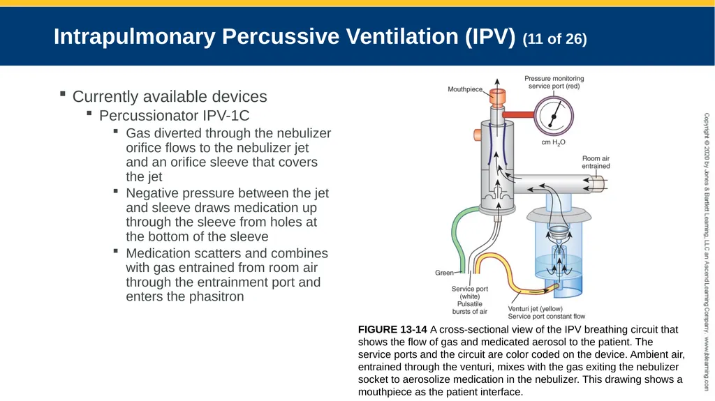
Gas diverted through the nebulizer orifice flows to the nebulizer jet and an orifice sleeve that covers the jet
Negative pressure between the jet and sleeve draws medication up through the sleeve from holes at the bottom of the sleeve
Medication scatters and combines with gas entrained from room air through the entrainment port and enters the phasitron FIGURE 13-14 A cross-sectional view of the IPV breathing circuit that shows the flow of gas and medicated aerosol to the patient. The service ports and the circuit are color coded on the device. Ambient air, entrained through the venturi, mixes with the gas exiting the nebulizer socket to aerosolize medication in the nebulizer. This drawing shows a mouthpiece as the patient interface.<br>
slide42. Intrapulmonary Percussive Ventilation (IPV) (12 of 26) Currently available devices
Percussionator IPV-1C
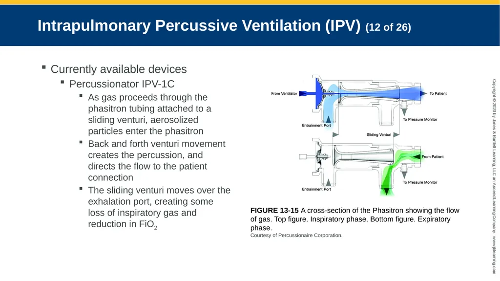
As gas proceeds through the phasitron tubing attached to a sliding venturi, aerosolized particles enter the phasitron
Back and forth venturi movement creates the percussion, and directs the flow to the patient connection
The sliding venturi moves over the exhalation port, creating some loss of inspiratory gas and reduction in FiO2 FIGURE 13-15 A cross-section of the Phasitron showing the flow of gas. Top figure. Inspiratory phase. Bottom figure. Expiratory phase.
Courtesy of Percussionaire Corporation.<br>
slide43. Intrapulmonary Percussive Ventilation (IPV) (13 of 26) Currently available devices
Percussive Neb IPPV
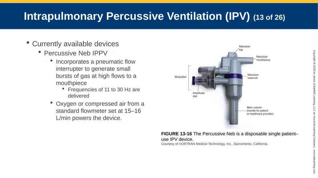
Incorporates a pneumatic flow interrupter to generate small bursts of gas at high flows to a mouthpiece
Frequencies of 11 to 30 Hz are delivered
Oxygen or compressed air from a standard flowmeter set at 15–16 L/min powers the device. FIGURE 13-16 The Percussive Neb is a disposable single patient–use IPV device.
Courtesy of VORTRAN Medical Technology, Inc., Sacramento, California.<br>
slide44. Intrapulmonary Percussive Ventilation (IPV) (14 of 26) Currently available devices
Percussive Neb IPPV
Pressures of 20 to 40 cm H2O may be delivered and adjusted by rotating the amplitude dial
The amplitude dial does not have reference marks
It is visually displayed on the pressure manometer incorporated into the unit
IE ratios of 12 to 13 are delivered and vary depending on the oscillation frequency.
The higher the frequency, the lower the IE<br>
slide45. Intrapulmonary Percussive Ventilation (IPV) (15 of 26) Currently available devices
Percussive Neb IPPV
This device is also capable of delivering medicated aerosol therapy in addition to positive pressure required for lung expansion
The nebulizer output is approximately 1 mL/min
The single-patient-use manifold device cannot be used with a mechanical ventilator<br>
slide46. Intrapulmonary Percussive Ventilation (IPV) (16 of 26) Currently available devices
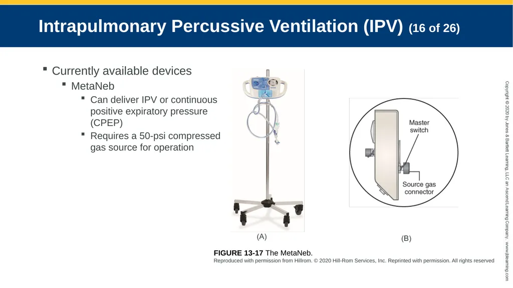
MetaNeb
Can deliver IPV or continuous positive expiratory pressure (CPEP)
Requires a 50-psi compressed gas source for operation FIGURE 13-17 The MetaNeb.
Reproduced with permission from Hillrom. © 2020 Hill-Rom Services, Inc. Reprinted with permission. All rights reserved<br>
slide47. Intrapulmonary Percussive Ventilation (IPV) (17 of 26) Currently available devices
MetaNeb
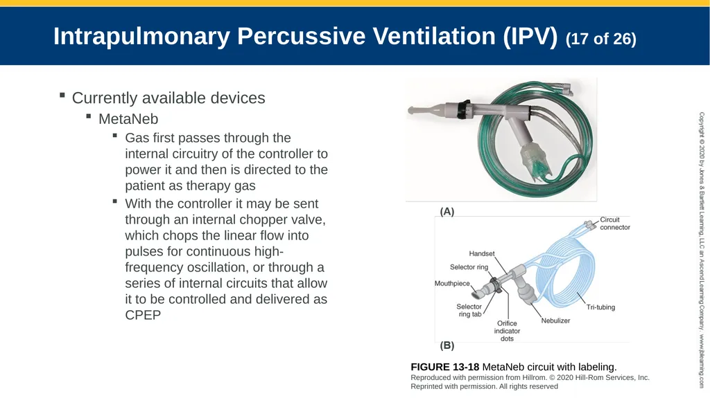
Gas first passes through the internal circuitry of the controller to power it and then is directed to the patient as therapy gas
With the controller it may be sent through an internal chopper valve, which chops the linear flow into pulses for continuous high-frequency oscillation, or through a series of internal circuits that allow it to be controlled and delivered as CPEP FIGURE 13-18 MetaNeb circuit with labeling.
Reproduced with permission from Hillrom. © 2020 Hill-Rom Services, Inc. Reprinted with permission. All rights reserved<br>
slide48. Intrapulmonary Percussive Ventilation (IPV) (18 of 26) Currently available devices
MetaNeb
The high-frequency pulses are calibrated to deliver IE ratios of approximately 12
A portion of the supply gas is used to power the nebulizer<br>
slide49. Intrapulmonary Percussive Ventilation (IPV) (19 of 26) Currently available devices
MetaNeb
The front panel contains a pressure manometer, a tri-connector for the patient circuit, and three control knobs
The mode selector knob allows the operator to choose continuous high frequency oscillation (CHFO), continuous positive expiratory pressure (CPEP), or just the nebulizer (Aerosol Only)
If CHFO is selected, a second control switch allows for pressure adjustment of the pulsatile breath rate and pulse amplitude
The third control knob allows the inspiratory flow to be set and is functional in the CPEP mode<br>
slide50. Intrapulmonary Percussive Ventilation (IPV) (20 of 26) Currently available devices
MetaNeb
The patient circuit connects to the controller with a tri-connector located just below the mode selector
A single connector is located on the distal end of the patient circuit, which attaches to the controller and is secured in place with two locking mechanisms<br>
slide51. Intrapulmonary Percussive Ventilation (IPV) (21 of 26) Currently available devices
MetaNeb
Proximal to the tri-connector are three tubes connected to one another, and a handset
One tube transports therapy gas from the controller to the back of the handset
A second tube supplies flow to the nebulizer
A third tube transmits pressure from the handset directly to the manometer<br>
slide52. Intrapulmonary Percussive Ventilation (IPV) (22 of 26) Currently available devices
MetaNeb
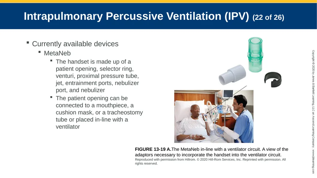
The handset is made up of a patient opening, selector ring, venturi, proximal pressure tube, jet, entrainment ports, nebulizer port, and nebulizer
The patient opening can be connected to a mouthpiece, a cushion mask, or a tracheostomy tube or placed in-line with a ventilator FIGURE 13-19 A.The MetaNeb in-line with a ventilator circuit. A view of the adaptors necessary to incorporate the handset into the ventilator circuit.
Reproduced with permission from Hillrom. © 2020 Hill-Rom Services, Inc. Reprinted with permission. All rights reserved.<br>
slide53. Intrapulmonary Percussive Ventilation (IPV) (23 of 26) Currently available devices
MetaNeb
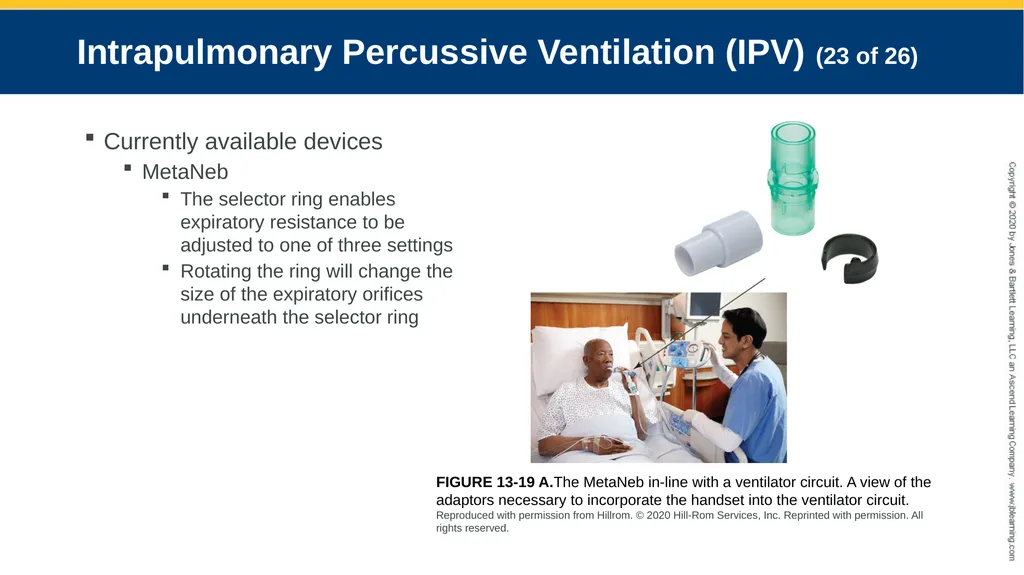
The selector ring enables expiratory resistance to be adjusted to one of three settings
Rotating the ring will change the size of the expiratory orifices underneath the selector ring FIGURE 13-19 A.The MetaNeb in-line with a ventilator circuit. A view of the adaptors necessary to incorporate the handset into the ventilator circuit.
Reproduced with permission from Hillrom. © 2020 Hill-Rom Services, Inc. Reprinted with permission. All rights reserved.<br>
slide54. Intrapulmonary Percussive Ventilation (IPV) (24 of 26) Currently available devices
MetaNeb
An occlusion ring is included with the circuit to replace the selector ring for use in-line with a ventilator
The venturi serves as a safety mechanism and regulates flow to the patient<br>
slide55. Intrapulmonary Percussive Ventilation (IPV) (25 of 26) Currently available devices
MetaNeb
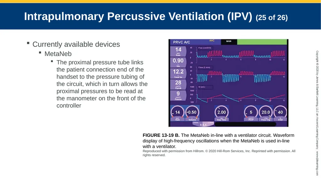
The proximal pressure tube links the patient connection end of the handset to the pressure tubing of the circuit, which in turn allows the proximal pressures to be read at the manometer on the front of the controller FIGURE 13-19 B. The MetaNeb in-line with a ventilator circuit. Waveform display of high-frequency oscillations when the MetaNeb is used in-line with a ventilator.
Reproduced with permission from Hillrom. © 2020 Hill-Rom Services, Inc. Reprinted with permission. All rights reserved.<br>
slide56. Intrapulmonary Percussive Ventilation (IPV) (26 of 26) Currently available devices
MetaNeb
A jet in the rear of the handset funnels gas into the throat of the venturi and is surrounded by entrainment ports
The entrainment ports serve as a source of ingress for ambient gas, which is drawn into the venturi, and egress
Safety pop-off of sorts in the event of excessive back pressure
Aerosolized medication is produced by the nebulizer and entrained into the venturi via the nebulizer port<br>
slide57. Positive-Airway Pressure Devices (1 of 11) Uses
Treat atelectasis
Reduce work of breathing
Two approaches
PEP
CPAP<br>
slide58. Positive-Airway Pressure Devices (2 of 11) Positive expiratory pressure (PEP)
Positive expiratory pressure is applied to airway as the patient exhales against a resistance
A back pressure is created that stents the airway open and improves airway patency
PEP up to 20 cm H2O
Mimics pursed lip breathing
Many commercially available single patient–use devices<br>
slide59. Positive-Airway Pressure Devices (3 of 11) Continuous positive airway pressure (CPAP)
Constant airway pressure maintained during both inspiratory and expiratory phases
CPAP elevates intrathoracic pressure and alveolar pressure which, in turn, increases FRC and improves oxygenation
Can be applied continuously or intermittently through a valved mask
May be delivered noninvasively and invasively<br>
slide60. Positive-Airway Pressure Devices (4 of 11) Continuous positive airway pressure (CPAP)
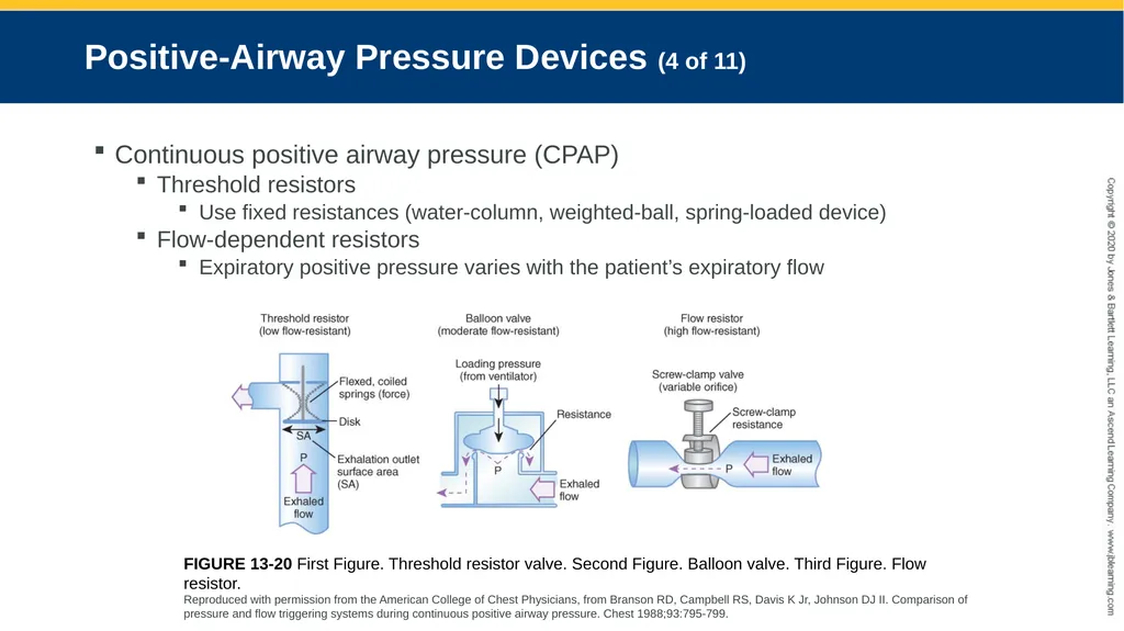
Threshold resistors
Use fixed resistances (water-column, weighted-ball, spring-loaded device)
Flow-dependent resistors
Expiratory positive pressure varies with the patient’s expiratory flow FIGURE 13-20 First Figure. Threshold resistor valve. Second Figure. Balloon valve. Third Figure. Flow resistor.
Reproduced with permission from the American College of Chest Physicians, from Branson RD, Campbell RS, Davis K Jr, Johnson DJ II. Comparison of pressure and flow triggering systems during continuous positive airway pressure. Chest 1988;93:795-799.<br>
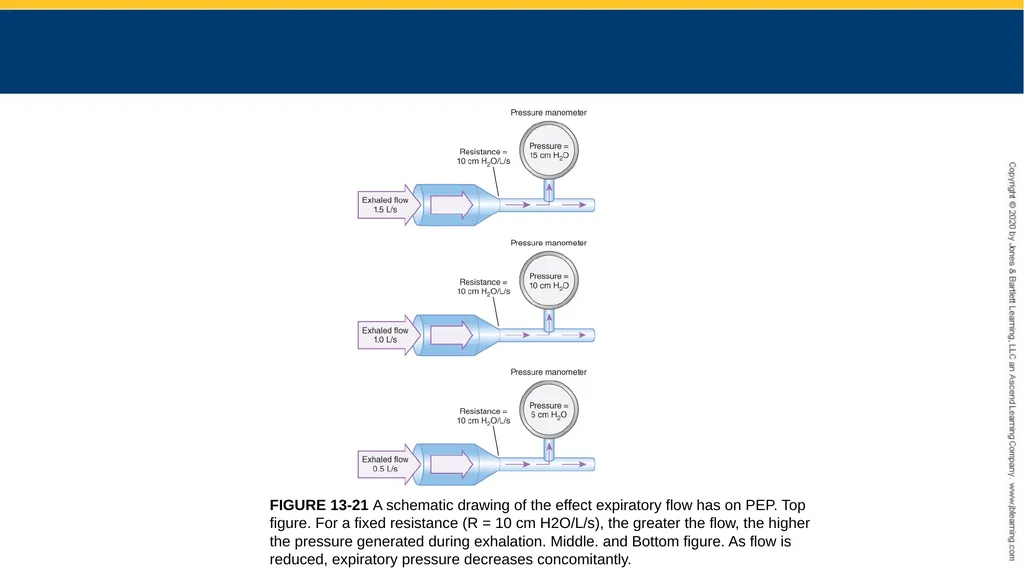
slide61. FIGURE 13-21 A schematic drawing of the effect expiratory flow has on PEP. Top figure. For a fixed resistance (R = 10 cm H2O/L/s), the greater the flow, the higher the pressure generated during exhalation. Middle. and Bottom figure. As flow is reduced, expiratory pressure decreases concomitantly.<br>
slide62. Positive-Airway Pressure Devices (5 of 11) Continuous positive airway pressure (CPAP)
Uses or indications
Decreases the work of breathing and reduces air trapping
Facilitates the cephalad mobilization of retained secretions
Stents the airway open as treatment for obstructive sleep apnea<br>
slide63. Positive-Airway Pressure Devices (6 of 11) Continuous positive airway pressure (CPAP)
Types
Underwater seal (bubble CPAP) water column
Water column threshold resistors
Adjusting the water level to achieve a target pressure
Typically used in neonates
Inexpensive
Uses a continuous flow source at a specified FiO2<br>
slide64. Positive-Airway Pressure Devices (7 of 11) Continuous positive airway pressure (CPAP)
Types
Spring-loaded valve
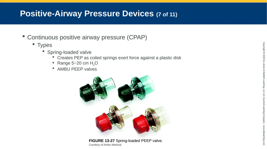
Creates PEP as coiled springs exert force against a plastic disk
Range 5−20 cm H2O
AMBU PEEP valves FIGURE 13-27 Spring-loaded PEEP valve.
Courtesy of Ambu Medical.<br>
slide65. Positive-Airway Pressure Devices (8 of 11) Continuous positive airway pressure (CPAP)
Types
Magnetic valve
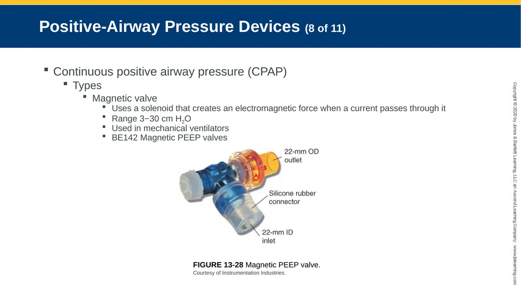
Uses a solenoid that creates an electromagnetic force when a current passes through it
Range 3−30 cm H2O
Used in mechanical ventilators
BE142 Magnetic PEEP valves FIGURE 13-28 Magnetic PEEP valve.
Courtesy of Instrumentation Industries.<br>
slide66. Positive-Airway Pressure Devices (9 of 11) Devices used to provide PEP therapy
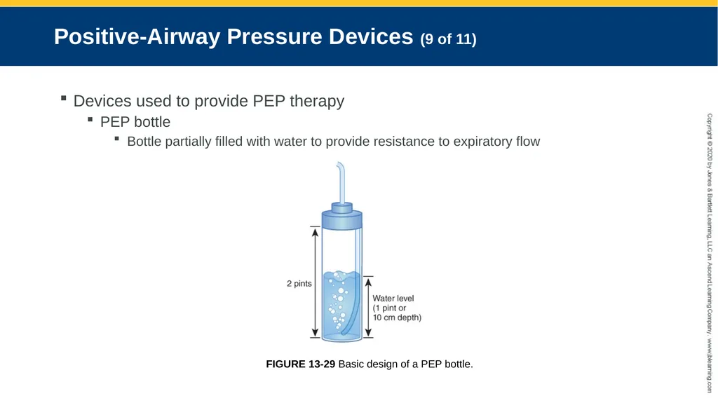
PEP bottle
Bottle partially filled with water to provide resistance to expiratory flow FIGURE 13-29 Basic design of a PEP bottle.<br>
slide67. Positive-Airway Pressure Devices (10 of 11) Devices used to provide PEP therapy
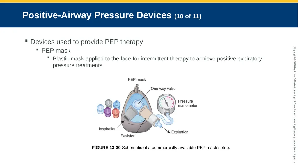
PEP mask
Plastic mask applied to the face for intermittent therapy to achieve positive expiratory pressure treatments FIGURE 13-30 Schematic of a commercially available PEP mask setup.<br>
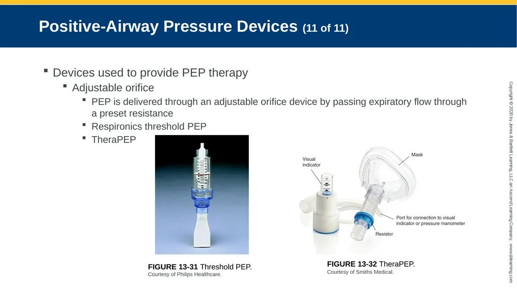
slide68. Positive-Airway Pressure Devices (11 of 11) Devices used to provide PEP therapy
Adjustable orifice
PEP is delivered through an adjustable orifice device by passing expiratory flow through a preset resistance
Respironics threshold PEP
TheraPEP FIGURE 13-31 Threshold PEP.
Courtesy of Philips Healthcare. FIGURE 13-32 TheraPEP.
Courtesy of Smiths Medical.<br>
slide2. Objectives Incentive spirometry
Intermittent positive-pressure breathing
Intrapulmonary percussive ventilation
Positive airway pressure adjuncts<br>
slide3. Introduction (1 of 2) Hyperinflation therapy (HT) is also known as lung expansion maneuvers
Subjects the lungs to volumes greater than normal to reinflate collapsed areas and improve gas exchange
Used to prevent/treat atelectasis
The treatment of atelectasis is dependent on its underlying origin and pathophysiology<br>
slide4. Introduction (2 of 2) Atelectasis is classified by its origin
Airway obstruction (resorption)
Abdominal distention (compression)
Hypoventilation (passive)
May benefit from hyperinflation therapy
Increased surface tension (adhesive)
May benefit from hyperinflation therapy<br>
slide5. Incentive Spirometer (IS) (1 of 10) A low-level resistance breathing exercise
Incorporates sustained maximal inspiration (SMI)
The equivalent of a deep breath or sigh that is routinely generated by a spontaneous yawn
Goal-oriented device that use visual aids such as raising a lightweight ball or indicator to gauge progress toward goal attainment
Devices are either flow or volume oriented<br>
slide6. Incentive Spirometer (IS) (2 of 10) Clinical outcomes are based on repetition of deep breaths that results in airway patency and in turn treats the underlying cause of the atelectasis
Evidence of lung expansion including observation of chest rise and confirmation of lung volume achieved is greater using a volume-oriented compared to a flow-oriented devices<br>
slide7. Incentive Spirometer (IS) (3 of 10) Application
Adjunct for deep breathing across the care continuum
Inspiratory breath-holding for at least 3 to 10 seconds followed by passive exhalation
Postoperative reversal of atelectasis
Mild restrictive diseases affected by abnormal diaphragm function
Management of atelectasis in sickle cell disease and prevention of complications associated with acute chest syndrome<br>
slide8. Incentive Spirometer (IS) (4 of 10) Application
IS therapy is not completely benign
May induce hyperventilation
Hypoxia may occur if supplemental oxygen therapy is interrupted while the patient performs the maneuver
Patients may experience weakness or fatigue
Discomfort related to incisional or procedural pain may occur
Patients at risk for air leak or those who present with underlying obstructive lung disease may be at risk for bronchospasm (asthma) or barotrauma (emphysema)
Patients with COPD may have air-trapping and hyperinflation<br>
slide9. Incentive Spirometer (IS) (5 of 10) Application
Should not be used with:
Unconscious patients
Patients with no cognitive abilities
Those unable to reproduce the maneuver because of significant reduction in pulmonary mechanics
Vital capacity less than 10 mL/kg
Inspiratory capacity less than one-third predicted normal
Care should be taken to monitor patients and assure an understanding of how to perform the technique properly<br>
slide10. Incentive Spirometer (IS) (6 of 10) Principles of operation
Volume-oriented
Integrate concept of true and precise volume displacement
During inspiration, the device’s indicator rises concomitantly with the change in volume
Diaphragmatic motion is increased when using a volume-oriented spirometer compared to its flow-oriented counterpart<br>
slide11. Incentive Spirometer (IS) (7 of 10) Principles of operation
Flow-oriented
Directly measures flow
Volume is calculated based on flow measurements and times
The rise of one ball (or more) indicates the flow generated
A rise in flow is an indirect indicator that the volume has increased
Beneficial effect is related to the performance of SMI
Flow is measured in mL/sec and operational ranges vary among devices<br>
slide12. Incentive Spirometer (IS) (8 of 10) Currently available devices
Volume-oriented
Voldyne exercisers
Three sizes including a pediatric size
The Coach 2
An adult and a pediatric model FIGURE 13-1 Schematic of the Voldyne Volume-Dependent Incentive Spirometer. FIGURE 13-3 The Coach Volume-Dependent Incentive Spirometer. A. The pediatric model with maximum volume displacement of 2.0 L. B. The adult model with maximum volume displacement of 4.0 L.
Courtesy of Smiths Medical.<br>
slide13. Incentive Spirometer (IS) (9 of 10) Currently available devices
Flow-oriented
Clini-Flow
Hudson RCI LVE FIGURE 13-4 The CliniFLO (Smiths Medical) is an example of a flow-oriented incentive spirometer. The flow setting is adjustable, from 100 to 600 mL/s, enabling this device to be used across a spectrum of patient populations.
Courtesy of Smiths Medical. FIGURE 13-5 The Hudson RCI Lung Volume Exerciser (Teleflex Medical) is a flow-oriented incentive spirometer with operational flow ranges of 200 to 1200 cc/s.
Courtesy of Teleflex.<br>
slide14. Incentive Spirometer (IS) (10 of 10) TABLE 13-1 Troubleshooting Guide for Patient and Equipment Problems Commonly Associated with Incentive Spirometers<br>
slide15. Intermittent Positive Pressure Breathing (IPPB) (1 of 12) Utilizes a mechanical positive pressure device
Delivers a controlled airflow into the lungs at a predetermined pressure when triggered by spontaneous breathing activities
Can be flow, pressure, or time cycled
Delivered by a stand-alone positive pressure device or through an invasive or noninvasive ventilator<br>
slide16. Intermittent Positive Pressure Breathing (IPPB) (2 of 12) Application
Inpatient, outpatient, and in-home settings
Can be used on patients with cognitive limitations
Variety of interfaces (e.g., mouthpiece, mask, mouth shield, or direct connection to an artificial airway)
Brief treatment length (20 to minutes)
Patients seated in semi-Fowler<br>
slide17. Intermittent Positive Pressure Breathing (IPPB) (3 of 12) Application
Settings
P = 10–15 cm H2O (initially)
IE = 13
Trigger threshold set to reduce the patient’s inspiratory work and minimize risk of auto-triggering
Inspiratory pressure is then slowly increased until a minimum delivered volume of at least one-third of the patient’s inspiratory capacity is achieved<br>
slide18. Intermittent Positive Pressure Breathing (IPPB) (4 of 12) Application
Used to treat postoperative atelectasis
Untreated chest pneumothorax is an absolute contraindication
Relative contraindications include hemodynamic instability, blebs, recent facial, oral, skull, or esophageal surgeries, TE fistula, and nausea
Hazards and complications include, but are not limited to, gastric distension, nosocomial infection, hypoxemia, hypocarbia, hemoptysis, decreased venous return, air trapping, and barotrauma<br>
slide19. Intermittent Positive Pressure Breathing (IPPB) (5 of 12) Principles of operation
Setting of a PIP, PEEP during PCV on a noninvasive ventilator
Appropriate interface should be selected
Pressure or flow triggered
Flow is variable upon patient demand
PSV can also be used to deliver IPPB<br>
slide20. Intermittent Positive Pressure Breathing (IPPB) (6 of 12) Principles of operation
IPPB can be delivered with
Electrically or pneumatically powered devices
Hybrid flow devices<br>
slide21. Intermittent Positive Pressure Breathing (IPPB) (7 of 12) Currently available devices
Puritan Bennett AP-5
Electrically powered
Bird Mark 7
Pneumatically powered
Vortran IPPB
Pneumatically powered hybrid device<br>
slide22. Intermittent Positive Pressure Breathing (IPPB) (8 of 12) Puritan Bennett AP-5
Electronically powered
Pressure-triggered
Pressure-targeted
Flow-cycled device
Primary use is in settings where high-pressure compressed gas is not available
Home care
Long-term care FIGURE 13-6 The Bennett valve controls the flow of gas during inspiration and expiration. During inspiration, the vane drum rotates clockwise, or upward, into an open position to let gas flow from the pressure control regulator to the nebulizer. The vane drum, with the Bennett valve, rotates counterclockwise during expiration, directing the flow of gas from the pressure regulator to the dump port.
©2020 Medtronic. All rights reserved. Used with the permission of Medtronic.<br>
slide23. Intermittent Positive Pressure Breathing (IPPB) (9 of 12) Bird Mark 7
Pneumatically powered
Pressure-controlled
Delivers inspiratory pressures in the range of 10–60 cm H2O
Inspiration may be triggered by time, pressure, or manually pushing the hand timer rod FIGURE 13-7 The Bird Mark 7. The first of several generations of Bird IPPB units that were commercially available in the early 1950s.
Courtesy of Percussionaire Corporation.<br>
slide24. Intermittent Positive Pressure Breathing (IPPB) (10 of 12) Bird Mark 7
Positive pressure breaths are pressure or time cycled
Both breath phases incorporate a change in pressure and depend on an attraction of a metal clutch plate to a magnet to trigger or initiate a positive pressure breath or to cycle the breath off FIGURE 13-8 The use of pressure gradients and magnetism with the Bird Mark series of devices used for IPPB. Top figure. The pressure of both chambers is equal. Middle figure. The pressure on the patient side of the chamber drops as a result of an inspiratory effort. Bottom figure. The clutch plate and magnet shift to the left as pressure on the right, or patient, side increases during inspiration.<br>
slide25. Intermittent Positive Pressure Breathing (IPPB) (11 of 12) Voltran IPPB
Pneumatically powered
Flows up to 40 L/min are achievable when connected to a 50-psi source
Flow rates of 15 to 40 L/min can be generated when connected to a standard flowmeter
Disposable single patient use FIGURE 13-9 The VORTRAN-IPPB, a disposable, single patient–use device.
Courtesy of VORTRAN Medical Technology, Inc., Sacramento, California.<br>
slide26. Intermittent Positive Pressure Breathing (IPPB) (12 of 12) Voltran IPPB
The modulator is an adjustable spring-loaded valve
Can provide inspiratory pressures from 20 to 50 cm H2O and baseline pressures of PEEP from 2 to 5 cm H2O
The aerosol generator operates from a demand valve
This air entrainment valve allows the patient to access fresh gas, which is drawn in through the nebulizer, if needed
The nebulizer reservoir can hold up to 20 mL of an aqueous solution
Inspiratory time and breath rate are adjustable from 0.5 to 3.0 seconds and 8 to 20 breaths per minute<br>
slide27. Hybrid IPPB/PEP Device (1 of 4) EzPAP
Generate positive airway pressure on inspiration and positive expiratory pressure (PEP)
Enhances collateral ventilation in the airway with back pressure
Medicated aerosol therapy can be delivered in conjunction
Nebulizer does not alter pressure delivery
Device will obstruct the aerosol pathway
May significantly reduce aerosol particle size and patient dose<br>
slide28. Hybrid IPPB/PEP Device (2 of 4) EzPAP
Principles of operation
Oxygen supply tubing is connected to a compressed gas source on one end and to the gas inlet port on the other, and flow is set at 5−15 L/min
Patient exhales against a flow or resistance generating expiratory pressure
The greater the inspiratory flow, the lower the pressure delivered to the airway
The greater the expiratory flow, the higher the PEP FIGURE 13-10 Parts of the EzPAP (Smiths Medical) designed to provide hyperinflation therapy.
Courtesy of Smiths Medical.<br>
slide29. Hybrid IPPB/PEP Device (3 of 4) AccuPap
Generates positive airway pressure on inspiration and positive expiratory pressure (PEP)
Incorporates a variable orifice threshold resistor to impede exhaled flow and generate PEP
The patient inspires through the device and exhales against a resistance, generating a positive expiratory pressure
Medicated aerosol therapy can be delivered in conjunction<br>
slide30. Hybrid IPPB/PEP Device (4 of 4) AccuPap
Principles of operation
Oxygen supply tubing is connected to a gas source on one end and to the gas inlet port on the other, and flow is set at 10 L/min
The operator adjusts the spring- loaded threshold resistor to the desired positive pressure setting
Pressures are adjustable from 5 to 20 cm H2O in 5-cm H2O increments
A pressure gauge can be connected to the pressure port for monitoring FIGURE 13-11 AccuPAP (Pulmodyne Medical) single patient–
use device for hyperinflation therapy.
Courtesy of Pulmodyne Inc<br>
slide31. Intrapulmonary Percussive Ventilation (IPV) (1 of 26) Combines hyperinflation therapy and airway clearance therapy
Application of high-frequency pulses (100−300/min) superimposed on the patient’s spontaneous breathing pattern
Causes changes in transrespiratory pressure and facilitates the cephalad movement of secretions during passive exhalation<br>
slide32. Intrapulmonary Percussive Ventilation (IPV) (2 of 26) Convective flow, molecular diffusion, Taylor dispersion, and step-by-step inflation are integrated into IPV
Promotes alveolar gas mixing
Augments gas exchange
Enhances airway clearance
Stabilizes mean airway pressure (MAP) while increasing lung volume at a preset pressure<br>
slide33. Intrapulmonary Percussive Ventilation (IPV) (3 of 26) Application
Deliver aerosolized bronchodilators to patients with COPD
Expand collapsed alveoli
Treat atelectasis
Facilitate the secretion mobilization and removal
Neurodegenerative diseases
Cystic fibrosis
Inhalation injuries<br>
slide34. Intrapulmonary Percussive Ventilation (IPV) (4 of 26) Application
Percussive breaths can be manually or automatically triggered
Inpatient and outpatient settings
Applied
Noninvasively
Mask
Mouthpiece
Invasively
Inline with a ventilator circuit<br>
slide35. Intrapulmonary Percussive Ventilation (IPV) (5 of 26) Application
Absolute contraindication
Untreated tension pneumothorax
Relative contraindications
Increased intracranial pressure
TE fistula
Hemodynamic instability
Active hemoptysis
Nausea
Recent facial, oral, or cranial surgery
Untreated TB<br>
slide36. Intrapulmonary Percussive Ventilation (IPV) (6 of 26) Application
Potential hazards
Gastric insufflation
Hyperventilation
Hemodynamic compromise
Air leak
Pneumothorax
Air trapping
Alveolar overdistention<br>
slide37. Intrapulmonary Percussive Ventilation (IPV) (7 of 26) Application
To minimize the occurrence of vomiting and risk of aspiration, precautions should be taken to coordinate a patient’s meals or feeding schedule with therapy
Schedule treatments at least 1 hour after eating
Temporarily discontinue intermittent or continuous enteral nutrition by artificial means using gastrostomy or nasogastric tube feedings during treatment<br>
slide38. Intrapulmonary Percussive Ventilation (IPV) (8 of 26) Currently available devices
Percussionator IPV-1C
Four operator controls
Gas enters from a 50-psi high-pressure compressor to a pressure regulator
The operational pressure control adjusts the device’s working pressure to 20–50 psig
Aneroid gauge displays the operational pressure
The On/Off switch will open or prevent the flow of gas from the compressed gas source into the pressure regulator FIGURE 13-12 The Percussionator IPV-1C with labeled controls.
Courtesy of Percussionaire Corporation.<br>
slide39. Intrapulmonary Percussive Ventilation (IPV) (9 of 26) Currently available devices
Percussionator IPV-1C
Gas exits through sockets on the front panel of the device
The sockets direct gas flow to the nebulizer, phasitron, and remote outputs in the patient circuit as well as to a pressure manometer
Phasitorn creates high frequency bursts (100 to 300 bursts per minute) of flow
Percusson frequency adjustable from 1–11 Hz FIGURE 13-13 The Phasitron portion of the IPV breathing circuit incorporating the sliding venturi and the small-volume nebulizer.
Courtesy of Percussionaire Corporation.<br>
slide40. Intrapulmonary Percussive Ventilation (IPV) (10 of 26) Currently available devices
Percussionator IPV-1C
Percussion frequency and pressure amplitude are inversely related
As the frequency is increased pressure amplitude decreases
A fixed inspiratory to expiratory (IE) ratio of 12 to 12.5 is typically used
A button is available on the front panel to allow inspiration to be manually triggered
The unit will remain in the inspiratory phase as long as this button is depressed
Manual releasing of this button will allow for passive exhalation<br>
slide41. Intrapulmonary Percussive Ventilation (IPV) (11 of 26) Currently available devices
Percussionator IPV-1C
Gas diverted through the nebulizer orifice flows to the nebulizer jet and an orifice sleeve that covers the jet
Negative pressure between the jet and sleeve draws medication up through the sleeve from holes at the bottom of the sleeve
Medication scatters and combines with gas entrained from room air through the entrainment port and enters the phasitron FIGURE 13-14 A cross-sectional view of the IPV breathing circuit that shows the flow of gas and medicated aerosol to the patient. The service ports and the circuit are color coded on the device. Ambient air, entrained through the venturi, mixes with the gas exiting the nebulizer socket to aerosolize medication in the nebulizer. This drawing shows a mouthpiece as the patient interface.<br>
slide42. Intrapulmonary Percussive Ventilation (IPV) (12 of 26) Currently available devices
Percussionator IPV-1C
As gas proceeds through the phasitron tubing attached to a sliding venturi, aerosolized particles enter the phasitron
Back and forth venturi movement creates the percussion, and directs the flow to the patient connection
The sliding venturi moves over the exhalation port, creating some loss of inspiratory gas and reduction in FiO2 FIGURE 13-15 A cross-section of the Phasitron showing the flow of gas. Top figure. Inspiratory phase. Bottom figure. Expiratory phase.
Courtesy of Percussionaire Corporation.<br>
slide43. Intrapulmonary Percussive Ventilation (IPV) (13 of 26) Currently available devices
Percussive Neb IPPV
Incorporates a pneumatic flow interrupter to generate small bursts of gas at high flows to a mouthpiece
Frequencies of 11 to 30 Hz are delivered
Oxygen or compressed air from a standard flowmeter set at 15–16 L/min powers the device. FIGURE 13-16 The Percussive Neb is a disposable single patient–use IPV device.
Courtesy of VORTRAN Medical Technology, Inc., Sacramento, California.<br>
slide44. Intrapulmonary Percussive Ventilation (IPV) (14 of 26) Currently available devices
Percussive Neb IPPV
Pressures of 20 to 40 cm H2O may be delivered and adjusted by rotating the amplitude dial
The amplitude dial does not have reference marks
It is visually displayed on the pressure manometer incorporated into the unit
IE ratios of 12 to 13 are delivered and vary depending on the oscillation frequency.
The higher the frequency, the lower the IE<br>
slide45. Intrapulmonary Percussive Ventilation (IPV) (15 of 26) Currently available devices
Percussive Neb IPPV
This device is also capable of delivering medicated aerosol therapy in addition to positive pressure required for lung expansion
The nebulizer output is approximately 1 mL/min
The single-patient-use manifold device cannot be used with a mechanical ventilator<br>
slide46. Intrapulmonary Percussive Ventilation (IPV) (16 of 26) Currently available devices
MetaNeb
Can deliver IPV or continuous positive expiratory pressure (CPEP)
Requires a 50-psi compressed gas source for operation FIGURE 13-17 The MetaNeb.
Reproduced with permission from Hillrom. © 2020 Hill-Rom Services, Inc. Reprinted with permission. All rights reserved<br>
slide47. Intrapulmonary Percussive Ventilation (IPV) (17 of 26) Currently available devices
MetaNeb
Gas first passes through the internal circuitry of the controller to power it and then is directed to the patient as therapy gas
With the controller it may be sent through an internal chopper valve, which chops the linear flow into pulses for continuous high-frequency oscillation, or through a series of internal circuits that allow it to be controlled and delivered as CPEP FIGURE 13-18 MetaNeb circuit with labeling.
Reproduced with permission from Hillrom. © 2020 Hill-Rom Services, Inc. Reprinted with permission. All rights reserved<br>
slide48. Intrapulmonary Percussive Ventilation (IPV) (18 of 26) Currently available devices
MetaNeb
The high-frequency pulses are calibrated to deliver IE ratios of approximately 12
A portion of the supply gas is used to power the nebulizer<br>
slide49. Intrapulmonary Percussive Ventilation (IPV) (19 of 26) Currently available devices
MetaNeb
The front panel contains a pressure manometer, a tri-connector for the patient circuit, and three control knobs
The mode selector knob allows the operator to choose continuous high frequency oscillation (CHFO), continuous positive expiratory pressure (CPEP), or just the nebulizer (Aerosol Only)
If CHFO is selected, a second control switch allows for pressure adjustment of the pulsatile breath rate and pulse amplitude
The third control knob allows the inspiratory flow to be set and is functional in the CPEP mode<br>
slide50. Intrapulmonary Percussive Ventilation (IPV) (20 of 26) Currently available devices
MetaNeb
The patient circuit connects to the controller with a tri-connector located just below the mode selector
A single connector is located on the distal end of the patient circuit, which attaches to the controller and is secured in place with two locking mechanisms<br>
slide51. Intrapulmonary Percussive Ventilation (IPV) (21 of 26) Currently available devices
MetaNeb
Proximal to the tri-connector are three tubes connected to one another, and a handset
One tube transports therapy gas from the controller to the back of the handset
A second tube supplies flow to the nebulizer
A third tube transmits pressure from the handset directly to the manometer<br>
slide52. Intrapulmonary Percussive Ventilation (IPV) (22 of 26) Currently available devices
MetaNeb
The handset is made up of a patient opening, selector ring, venturi, proximal pressure tube, jet, entrainment ports, nebulizer port, and nebulizer
The patient opening can be connected to a mouthpiece, a cushion mask, or a tracheostomy tube or placed in-line with a ventilator FIGURE 13-19 A.The MetaNeb in-line with a ventilator circuit. A view of the adaptors necessary to incorporate the handset into the ventilator circuit.
Reproduced with permission from Hillrom. © 2020 Hill-Rom Services, Inc. Reprinted with permission. All rights reserved.<br>
slide53. Intrapulmonary Percussive Ventilation (IPV) (23 of 26) Currently available devices
MetaNeb
The selector ring enables expiratory resistance to be adjusted to one of three settings
Rotating the ring will change the size of the expiratory orifices underneath the selector ring FIGURE 13-19 A.The MetaNeb in-line with a ventilator circuit. A view of the adaptors necessary to incorporate the handset into the ventilator circuit.
Reproduced with permission from Hillrom. © 2020 Hill-Rom Services, Inc. Reprinted with permission. All rights reserved.<br>
slide54. Intrapulmonary Percussive Ventilation (IPV) (24 of 26) Currently available devices
MetaNeb
An occlusion ring is included with the circuit to replace the selector ring for use in-line with a ventilator
The venturi serves as a safety mechanism and regulates flow to the patient<br>
slide55. Intrapulmonary Percussive Ventilation (IPV) (25 of 26) Currently available devices
MetaNeb
The proximal pressure tube links the patient connection end of the handset to the pressure tubing of the circuit, which in turn allows the proximal pressures to be read at the manometer on the front of the controller FIGURE 13-19 B. The MetaNeb in-line with a ventilator circuit. Waveform display of high-frequency oscillations when the MetaNeb is used in-line with a ventilator.
Reproduced with permission from Hillrom. © 2020 Hill-Rom Services, Inc. Reprinted with permission. All rights reserved.<br>
slide56. Intrapulmonary Percussive Ventilation (IPV) (26 of 26) Currently available devices
MetaNeb
A jet in the rear of the handset funnels gas into the throat of the venturi and is surrounded by entrainment ports
The entrainment ports serve as a source of ingress for ambient gas, which is drawn into the venturi, and egress
Safety pop-off of sorts in the event of excessive back pressure
Aerosolized medication is produced by the nebulizer and entrained into the venturi via the nebulizer port<br>
slide57. Positive-Airway Pressure Devices (1 of 11) Uses
Treat atelectasis
Reduce work of breathing
Two approaches
PEP
CPAP<br>
slide58. Positive-Airway Pressure Devices (2 of 11) Positive expiratory pressure (PEP)
Positive expiratory pressure is applied to airway as the patient exhales against a resistance
A back pressure is created that stents the airway open and improves airway patency
PEP up to 20 cm H2O
Mimics pursed lip breathing
Many commercially available single patient–use devices<br>
slide59. Positive-Airway Pressure Devices (3 of 11) Continuous positive airway pressure (CPAP)
Constant airway pressure maintained during both inspiratory and expiratory phases
CPAP elevates intrathoracic pressure and alveolar pressure which, in turn, increases FRC and improves oxygenation
Can be applied continuously or intermittently through a valved mask
May be delivered noninvasively and invasively<br>
slide60. Positive-Airway Pressure Devices (4 of 11) Continuous positive airway pressure (CPAP)
Threshold resistors
Use fixed resistances (water-column, weighted-ball, spring-loaded device)
Flow-dependent resistors
Expiratory positive pressure varies with the patient’s expiratory flow FIGURE 13-20 First Figure. Threshold resistor valve. Second Figure. Balloon valve. Third Figure. Flow resistor.
Reproduced with permission from the American College of Chest Physicians, from Branson RD, Campbell RS, Davis K Jr, Johnson DJ II. Comparison of pressure and flow triggering systems during continuous positive airway pressure. Chest 1988;93:795-799.<br>
slide61. FIGURE 13-21 A schematic drawing of the effect expiratory flow has on PEP. Top figure. For a fixed resistance (R = 10 cm H2O/L/s), the greater the flow, the higher the pressure generated during exhalation. Middle. and Bottom figure. As flow is reduced, expiratory pressure decreases concomitantly.<br>
slide62. Positive-Airway Pressure Devices (5 of 11) Continuous positive airway pressure (CPAP)
Uses or indications
Decreases the work of breathing and reduces air trapping
Facilitates the cephalad mobilization of retained secretions
Stents the airway open as treatment for obstructive sleep apnea<br>
slide63. Positive-Airway Pressure Devices (6 of 11) Continuous positive airway pressure (CPAP)
Types
Underwater seal (bubble CPAP) water column
Water column threshold resistors
Adjusting the water level to achieve a target pressure
Typically used in neonates
Inexpensive
Uses a continuous flow source at a specified FiO2<br>
slide64. Positive-Airway Pressure Devices (7 of 11) Continuous positive airway pressure (CPAP)
Types
Spring-loaded valve
Creates PEP as coiled springs exert force against a plastic disk
Range 5−20 cm H2O
AMBU PEEP valves FIGURE 13-27 Spring-loaded PEEP valve.
Courtesy of Ambu Medical.<br>
slide65. Positive-Airway Pressure Devices (8 of 11) Continuous positive airway pressure (CPAP)
Types
Magnetic valve
Uses a solenoid that creates an electromagnetic force when a current passes through it
Range 3−30 cm H2O
Used in mechanical ventilators
BE142 Magnetic PEEP valves FIGURE 13-28 Magnetic PEEP valve.
Courtesy of Instrumentation Industries.<br>
slide66. Positive-Airway Pressure Devices (9 of 11) Devices used to provide PEP therapy
PEP bottle
Bottle partially filled with water to provide resistance to expiratory flow FIGURE 13-29 Basic design of a PEP bottle.<br>
slide67. Positive-Airway Pressure Devices (10 of 11) Devices used to provide PEP therapy
PEP mask
Plastic mask applied to the face for intermittent therapy to achieve positive expiratory pressure treatments FIGURE 13-30 Schematic of a commercially available PEP mask setup.<br>
slide68. Positive-Airway Pressure Devices (11 of 11) Devices used to provide PEP therapy
Adjustable orifice
PEP is delivered through an adjustable orifice device by passing expiratory flow through a preset resistance
Respironics threshold PEP
TheraPEP FIGURE 13-31 Threshold PEP.
Courtesy of Philips Healthcare. FIGURE 13-32 TheraPEP.
Courtesy of Smiths Medical.<br>