
Module VI Deterministic safety analysis F. Adorján
SN
Published · 127 slides · 0 views

1 / 1







Description
Module VI Deterministic safety analysis F. Adorján HAEA (retired) ferencadorjangmail.com Learning objectives After completing Module 6, the trainee will be: able to understand the essence and the methodology of deterministic safety
Related Topics
Share
Embed code
Download this presentation From Below
"Module VI Deterministic safety analysis F. Adorján" is the property of its rightful owner. Permission is granted to download and print the materials on this website for personal, non-commercial use only, and to display it on your personal computer provided you do not modify the materials and that you retain all copyright notices contained in the materials. By downloading content from our website, you accept the terms of this agreement.
Presentation Transcript
01
Module VI
Deterministic safety analysis F. Adorján
HAEA (retired)
ferencadorjan@gmail.com<br>
HAEA (retired)
ferencadorjan@gmail.com<br>
02
Learning objectives After completing Module 6, the trainee will be:
able to understand the essence and the methodology of deterministic safety analyses.
able to understand the significance of plant states and the related safety analyses.
able to understand the concept of postulated initiating events and the methodology for selecting them.
able to understand the difference between conservative and best estimate approaches.
familiar with the different applications of deterministic analyses. 7 - 18 May & 18 - 29 June 2018 Module 6 - DSA 2<br>
able to understand the essence and the methodology of deterministic safety analyses.
able to understand the significance of plant states and the related safety analyses.
able to understand the concept of postulated initiating events and the methodology for selecting them.
able to understand the difference between conservative and best estimate approaches.
familiar with the different applications of deterministic analyses. 7 - 18 May & 18 - 29 June 2018 Module 6 - DSA 2<br>
03
Contents Safety assessment – deterministic safety analysis
Plant states
Initiating events – postulated initiating event
Acceptance criteria
Types of deterministic safety analyses
Conservative deterministic safety analysis
Best estimate plus uncertainty analysis
Sensitivity and uncertainty analysis
Computer codes for deterministic safety analysis
Verification and validation of computer codes
Applications of deterministic safety analyses 7 - 18 May & 18 - 29 June 2018 Module 6 - DSA 3<br>
Plant states
Initiating events – postulated initiating event
Acceptance criteria
Types of deterministic safety analyses
Conservative deterministic safety analysis
Best estimate plus uncertainty analysis
Sensitivity and uncertainty analysis
Computer codes for deterministic safety analysis
Verification and validation of computer codes
Applications of deterministic safety analyses 7 - 18 May & 18 - 29 June 2018 Module 6 - DSA 3<br>
04
Safety assessment – deterministic safety analysis<br>
05
5 Safety assessment –
deterministic safety analysis Learning objectives
After completing this chapter, the trainee will be able to:
Describe the main purpose of performing safety analyses.
Identify whose responsibility is the performance of safety analyses.
Describe the main goals/outcomes of deterministic safety assessments. 5 7 - 18 May & 18 - 29 June 2018 Module 6 - DSA<br>
After completing this chapter, the trainee will be able to:
Describe the main purpose of performing safety analyses.
Identify whose responsibility is the performance of safety analyses.
Describe the main goals/outcomes of deterministic safety assessments. 5 7 - 18 May & 18 - 29 June 2018 Module 6 - DSA<br>
06
6 DETERMINISTIC SAFETY ANALYSIS - INTRODUCTION This Module covers Deterministic Safety Analyses, which are analytical studies aimed at demonstrating that safety requirements are met.
That corresponds to detailed, computational model based calculations or series of such calculations. The initial and boundary conditions shall be well defined (DETERMINISTIC) and shall be as closely reflecting the real technology, as possible or practicable.
They address all possible modes of normal operating conditions of the plant, assuming various initiating events.
They are essential elements of the plant design process and their review is central element of the licensing process. 6 7 - 18 May & 18 - 29 June 2018 Module 6 - DSA<br>
That corresponds to detailed, computational model based calculations or series of such calculations. The initial and boundary conditions shall be well defined (DETERMINISTIC) and shall be as closely reflecting the real technology, as possible or practicable.
They address all possible modes of normal operating conditions of the plant, assuming various initiating events.
They are essential elements of the plant design process and their review is central element of the licensing process. 6 7 - 18 May & 18 - 29 June 2018 Module 6 - DSA<br>
07
7 Safety analysis and safety assessment The terms “safety analysis” and “safety assessment” are sometimes used interchangeably.
When assessment and analysis are distinguished, then
the safety assessment is a general term, including any methodology to judge the safety of the plant or an activity;
the term safety analysis is used for model based transient and accident analysis calculations.
There are two main categories of safety analyses: the deterministic analysis and the probabilistic analysis. The results of these are often complemented by arguments based on engineering judgement or simple calculations. The safety assessment, i.e. the evaluation of safety is typically resulted from the combination of all these. 7 7 - 18 May & 18 - 29 June 2018 Module 6 - DSA<br>
When assessment and analysis are distinguished, then
the safety assessment is a general term, including any methodology to judge the safety of the plant or an activity;
the term safety analysis is used for model based transient and accident analysis calculations.
There are two main categories of safety analyses: the deterministic analysis and the probabilistic analysis. The results of these are often complemented by arguments based on engineering judgement or simple calculations. The safety assessment, i.e. the evaluation of safety is typically resulted from the combination of all these. 7 7 - 18 May & 18 - 29 June 2018 Module 6 - DSA<br>
08
About the safety assessment, in general In general, the goal of the safety assessment is to:
confirm that the design meets all design and safety requirements,
derive and verify the operational limits and conditions (OLC),
establish and validate possible accident conditions and
confirm that safety criteria which have been established to limit the harmful effects posed by the nuclear power plant (i.e. the radiological criteria), are met.
During the licensing process, typically an independent verification of the analyses is required. However, this does not relieve the Regulator from carrying out its own review.
All of this is to assure the regulator and the public that the nuclear power plant is safe to operate. 8 7 - 18 May & 18 - 29 June 2018 Module 6 - DSA<br>
confirm that the design meets all design and safety requirements,
derive and verify the operational limits and conditions (OLC),
establish and validate possible accident conditions and
confirm that safety criteria which have been established to limit the harmful effects posed by the nuclear power plant (i.e. the radiological criteria), are met.
During the licensing process, typically an independent verification of the analyses is required. However, this does not relieve the Regulator from carrying out its own review.
All of this is to assure the regulator and the public that the nuclear power plant is safe to operate. 8 7 - 18 May & 18 - 29 June 2018 Module 6 - DSA<br>
09
9 Ultimate purpose of safety assessments The Fundamental Safety Principles (SF-1) establishes the principles for ensuring the protection of workers, the public and the environment, now and in the future, from harmful effects of ionizing radiation.
Safety assessments are undertaken in order to demonstrating the compliance with fundamental safety principles and safety requirements for nuclear facilities.
The operating organization of the facility is responsible for the safety assessments and for their documentation. It also shall organize the independent validation of the assessment prior to submitting them to the regulatory body.
The safety assessment shall be regularly up-dated throughout the lifetime of the installation in order to demonstrate that the safety goals are continuously met. 9 7 - 18 May & 18 - 29 June 2018 Module 6 - DSA<br>
Safety assessments are undertaken in order to demonstrating the compliance with fundamental safety principles and safety requirements for nuclear facilities.
The operating organization of the facility is responsible for the safety assessments and for their documentation. It also shall organize the independent validation of the assessment prior to submitting them to the regulatory body.
The safety assessment shall be regularly up-dated throughout the lifetime of the installation in order to demonstrate that the safety goals are continuously met. 9 7 - 18 May & 18 - 29 June 2018 Module 6 - DSA<br>
10
10 Plant design models and data The plant design models and data, which are essential foundations for the safety analysis, should be kept up to date during the design phase and throughout the lifetime of the plant, including decommissioning.
In spite that these data are collected and maintained during the design phase by the designer, the prime responsibility stays always with the operating organization. Therefore the operating organization has to have access and has to review all data in detail.
The safety analyses assess the performance of the plant against a broad range of conditions (e.g. accident conditions) in order to obtain a complete understanding of how the plant is expected to perform in these – often very unlikely – situations. 10 7 - 18 May & 18 - 29 June 2018 Module 6 - DSA<br>
In spite that these data are collected and maintained during the design phase by the designer, the prime responsibility stays always with the operating organization. Therefore the operating organization has to have access and has to review all data in detail.
The safety analyses assess the performance of the plant against a broad range of conditions (e.g. accident conditions) in order to obtain a complete understanding of how the plant is expected to perform in these – often very unlikely – situations. 10 7 - 18 May & 18 - 29 June 2018 Module 6 - DSA<br>
11
11 How deterministic safety analyses are performed For deterministic safety analysis (DSA) the designer selects from the possible initiating events a specific sub-set: the postulated initiating events (PIEs) and by using appropriate models, simulates the response of the technology to high details.
Deterministic safety analyses use specific predetermined assumptions concerning the initial operational state and the initiating event, apply specific sets of rules and compare the results with the acceptance criteria. 11 7 - 18 May & 18 - 29 June 2018 Module 6 - DSA<br>
Deterministic safety analyses use specific predetermined assumptions concerning the initial operational state and the initiating event, apply specific sets of rules and compare the results with the acceptance criteria. 11 7 - 18 May & 18 - 29 June 2018 Module 6 - DSA<br>
12
12 What do deterministic safety analyses provide? Characterization of the postulated initiating events that are appropriate for the site and the design of the plant and also confirmation of the design bases for all items important to safety;
Analysis and evaluation of event sequences resulting from the PIEs set and confirm the qualification requirements for the related SSCs;
Comparison of the results of the analysis with acceptance criteria, design limits, dose limits;
Demonstration that the management of anticipated operational occurrences and design basis accident conditions is possible by automatic actuation of safety systems in combination with prescribed operator actions;
Demonstration that the management of design extension conditions is possible by automatic actuation of safety systems and by use of safety features together with expected operator actions. 12 7 - 18 May & 18 - 29 June 2018 Module 6 - DSA<br>
Analysis and evaluation of event sequences resulting from the PIEs set and confirm the qualification requirements for the related SSCs;
Comparison of the results of the analysis with acceptance criteria, design limits, dose limits;
Demonstration that the management of anticipated operational occurrences and design basis accident conditions is possible by automatic actuation of safety systems in combination with prescribed operator actions;
Demonstration that the management of design extension conditions is possible by automatic actuation of safety systems and by use of safety features together with expected operator actions. 12 7 - 18 May & 18 - 29 June 2018 Module 6 - DSA<br>
13
13 The use of DSA and PSA in combined manner It is an internationally accepted requirement that both deterministic and probabilistic safety analyses shall be used in a safety assessment of the design of nuclear power plants.
The two analysis approaches both support and complement each other.
The extent of the deterministic and probabilistic analyses carried out for a facility or activity shall be consistent with the graded approach.
Such analyses are an integral part of any licensing process and are part of the Final Safety Analysis Report (FSAR) for every nuclear power plant. 13 7 - 18 May & 18 - 29 June 2018 Module 6 - DSA<br>
The two analysis approaches both support and complement each other.
The extent of the deterministic and probabilistic analyses carried out for a facility or activity shall be consistent with the graded approach.
Such analyses are an integral part of any licensing process and are part of the Final Safety Analysis Report (FSAR) for every nuclear power plant. 13 7 - 18 May & 18 - 29 June 2018 Module 6 - DSA<br>
14
14 The use of both DSA and PSA Both types of safety analysis support the safe operation of the plant being the most important tool in developing and confirming
plant protection,
control system set points,
control parameters.
They are also used to establish and validate:
the plant’s operational limits and conditions (technical specifications),
normal operating procedures,
maintenance and inspection requirements,
emergency operating procedures (EOPs), and
severe accident management guidelines (SAMGs). 14 7 - 18 May & 18 - 29 June 2018 Module 6 - DSA<br>
plant protection,
control system set points,
control parameters.
They are also used to establish and validate:
the plant’s operational limits and conditions (technical specifications),
normal operating procedures,
maintenance and inspection requirements,
emergency operating procedures (EOPs), and
severe accident management guidelines (SAMGs). 14 7 - 18 May & 18 - 29 June 2018 Module 6 - DSA<br>
15
Plant states<br>
16
16 PLANT STATES Learning objectives
After completing this chapter, the trainee will be able to:
Describe different NPP plant states.
Distinguish between normal operational states and accident conditions.
Distinguish between design basis accidents and design extension conditions. 16 7 - 18 May & 18 - 29 June 2018 Module 6 - DSA<br>
After completing this chapter, the trainee will be able to:
Describe different NPP plant states.
Distinguish between normal operational states and accident conditions.
Distinguish between design basis accidents and design extension conditions. 16 7 - 18 May & 18 - 29 June 2018 Module 6 - DSA<br>
17
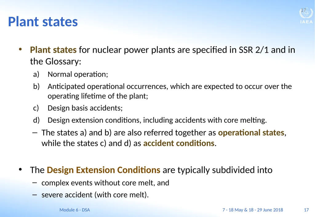
17 Plant states Plant states for nuclear power plants are specified in SSR 2/1 and in the Glossary:
Normal operation;
Anticipated operational occurrences, which are expected to occur over the operating lifetime of the plant;
Design basis accidents;
Design extension conditions, including accidents with core melting.
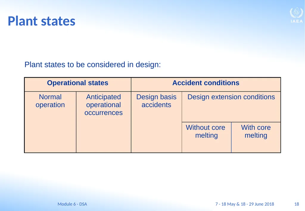
The states a) and b) are also referred together as operational states, while the states c) and d) as accident conditions.
The Design Extension Conditions are typically subdivided into
complex events without core melt, and
severe accident (with core melt). 17 7 - 18 May & 18 - 29 June 2018 Module 6 - DSA<br>
Normal operation;
Anticipated operational occurrences, which are expected to occur over the operating lifetime of the plant;
Design basis accidents;
Design extension conditions, including accidents with core melting.
The states a) and b) are also referred together as operational states, while the states c) and d) as accident conditions.
The Design Extension Conditions are typically subdivided into
complex events without core melt, and
severe accident (with core melt). 17 7 - 18 May & 18 - 29 June 2018 Module 6 - DSA<br>
18
18 Plant states Plant states to be considered in design: 7 - 18 May & 18 - 29 June 2018 Module 6 - DSA<br>
19
19 Normal operation Normal operation is defined as operation within the specified Operational Limits and Conditions (OLC).
Deterministic analysis is applied to normal operation with the aim of showing that normal operation can be carried out safely and in a stable manner.
This includes the requirement of no radiological consequences, i.e.:
acceptable doses to workers and
the public, and
acceptable planned releases of radioactive material. 19 7 - 18 May & 18 - 29 June 2018 Module 6 - DSA<br>
Deterministic analysis is applied to normal operation with the aim of showing that normal operation can be carried out safely and in a stable manner.
This includes the requirement of no radiological consequences, i.e.:
acceptable doses to workers and
the public, and
acceptable planned releases of radioactive material. 19 7 - 18 May & 18 - 29 June 2018 Module 6 - DSA<br>
20
20 Normal operation: requirements of the analysis The analysis should also provide the information that is needed:
to establish the set-points for the safety and control systems,
writing the operating procedures for the operating personnel and
defining the constraints for normal operation.
The assessment shall consider all modes of normal operation such as full power operation, low power operation, transients, shutdown (hot and cold) and refuelling, maintenance, etc.. 20 7 - 18 May & 18 - 29 June 2018 Module 6 - DSA<br>
to establish the set-points for the safety and control systems,
writing the operating procedures for the operating personnel and
defining the constraints for normal operation.
The assessment shall consider all modes of normal operation such as full power operation, low power operation, transients, shutdown (hot and cold) and refuelling, maintenance, etc.. 20 7 - 18 May & 18 - 29 June 2018 Module 6 - DSA<br>
21
21 Anticipated operational occurrences An anticipated operational occurrences (AOO) are events that are likely to occur during the lifetime of the plant. Therefore, specific systems shall be designed that make these events easily detectable and ensure the necessary high reliability counteractions, typically in automatic manner.
Such events have the potential to challenge the safety of the plant but, in view of appropriate design provisions, are not expected to cause any significant damage to items important to safety or to lead to an accident conditions.
If the specific systems fail performing their tasks, a design basis accident condition may occur. 21 7 - 18 May & 18 - 29 June 2018 Module 6 - DSA<br>
Such events have the potential to challenge the safety of the plant but, in view of appropriate design provisions, are not expected to cause any significant damage to items important to safety or to lead to an accident conditions.
If the specific systems fail performing their tasks, a design basis accident condition may occur. 21 7 - 18 May & 18 - 29 June 2018 Module 6 - DSA<br>
22
22 Anticipated operational occurrences Deterministic analysis is carried out to assess the response of the control and safety systems and to prove their robust nature of the design.
Generally, the analysis should consider uncertainties in modelling and data to demonstrate that there are margins to safety limits, even with conservative assumptions. 22 Anticipated operational occurrences typically include loss of normal off-site power, turbine trip, failure of control equipment and loss of power to a main coolant pump. 7 - 18 May & 18 - 29 June 2018 Module 6 - DSA<br>
Generally, the analysis should consider uncertainties in modelling and data to demonstrate that there are margins to safety limits, even with conservative assumptions. 22 Anticipated operational occurrences typically include loss of normal off-site power, turbine trip, failure of control equipment and loss of power to a main coolant pump. 7 - 18 May & 18 - 29 June 2018 Module 6 - DSA<br>
23
23 Design basis accidents Design basis accidents (DBAs) are accident conditions against which a facility is designed according to established design criteria.
In DBAs, the damage to the fuel and the release of radioactive material are kept within authorized limits.
It is a general expectation that the chance of occurrence of any such accident shall be around or below 1 % over the lifetime of the plant. For the latest designs a significant reduction of this probability is demonstrated by the safety analyses.
Typically the most demanding DBAs are the large coolant pipe and the steam line break cases. 23 7 - 18 May & 18 - 29 June 2018 Module 6 - DSA<br>
In DBAs, the damage to the fuel and the release of radioactive material are kept within authorized limits.
It is a general expectation that the chance of occurrence of any such accident shall be around or below 1 % over the lifetime of the plant. For the latest designs a significant reduction of this probability is demonstrated by the safety analyses.
Typically the most demanding DBAs are the large coolant pipe and the steam line break cases. 23 7 - 18 May & 18 - 29 June 2018 Module 6 - DSA<br>
24
24 Design extension conditions The essence of DEC is the introduction of additional measures to mitigate the consequences of complex accident sequences involving multiple failures and of severe accidents.
Deterministic analyses shall also be carried out for design extension conditions (DECs) including the severe accidents (SAs).
DECs are accident situations that may only develop in case of potential multiple failures of safety systems. All the consequences of possible single failures are supposed to be considered as part of the design basis.
The multiple failure accidents are of extremely low frequency, so they have not historically been considered within the design basis. 24 7 - 18 May & 18 - 29 June 2018 Module 6 - DSA<br>
Deterministic analyses shall also be carried out for design extension conditions (DECs) including the severe accidents (SAs).
DECs are accident situations that may only develop in case of potential multiple failures of safety systems. All the consequences of possible single failures are supposed to be considered as part of the design basis.
The multiple failure accidents are of extremely low frequency, so they have not historically been considered within the design basis. 24 7 - 18 May & 18 - 29 June 2018 Module 6 - DSA<br>
25
25 Design extension conditions: role of analysing DECs The principal role of the deterministic analysis of DECs is demonstrating the capabilities of the additional safety features designed to mitigate and limit the consequences of these cases.
Therefore, the effective method is to postulate initial plant damage states and then simulate the behaviour of the systems supposed to be available to mitigate and control the situation.
To prove the capabilities of designed safety features for DEC for maintaining the integrity of the containment even after a severe accident.
The analyses shall demonstrate the long term stability of the final state of the plant. 25 7 - 18 May & 18 - 29 June 2018 Module 6 - DSA<br>
Therefore, the effective method is to postulate initial plant damage states and then simulate the behaviour of the systems supposed to be available to mitigate and control the situation.
To prove the capabilities of designed safety features for DEC for maintaining the integrity of the containment even after a severe accident.
The analyses shall demonstrate the long term stability of the final state of the plant. 25 7 - 18 May & 18 - 29 June 2018 Module 6 - DSA<br>
26
Initiating event – postulated initiating event<br>
27
27 INITIATING EVENT –
postulated initiating event Learning objectives
After completing this chapter, the trainee will:
understand the notion and significance of postulated initiating events (PIE) and their possible causes.
describe the basis for grouping of initiating events.
distinguish the expected, possible, unlikely, remote and practically eliminated initiating events. 27 7 - 18 May & 18 - 29 June 2018 Module 6 - DSA<br>
After completing this chapter, the trainee will:
understand the notion and significance of postulated initiating events (PIE) and their possible causes.
describe the basis for grouping of initiating events.
distinguish the expected, possible, unlikely, remote and practically eliminated initiating events. 27 7 - 18 May & 18 - 29 June 2018 Module 6 - DSA<br>
28
28 Postulated Initiating Events (PIEs) The design for the nuclear power plant shall apply a systematic approach to identifying a comprehensive set of Postulated Initiating Events
All foreseeable events with the potential for serious consequences and from all foreseeable events with significant frequency of occurrence shall be considered
Look up “Initiating event” in the Glossary!
The primary causes of the initiating events may be:
Internal events (hazards), such as equipment failures or human errors, or
External hazards, such as earthquakes, floods, human induced hazards, etc. . 28 7 - 18 May & 18 - 29 June 2018 Module 6 - DSA<br>
All foreseeable events with the potential for serious consequences and from all foreseeable events with significant frequency of occurrence shall be considered
Look up “Initiating event” in the Glossary!
The primary causes of the initiating events may be:
Internal events (hazards), such as equipment failures or human errors, or
External hazards, such as earthquakes, floods, human induced hazards, etc. . 28 7 - 18 May & 18 - 29 June 2018 Module 6 - DSA<br>
29
29 Selection of Postulated Initiating Events (PIEs) The comprehensive listing of postulated initiating events (PIEs) shall cover all foreseeable failures of SSCs of the plant, as well as operating errors and possible failures arising from internal and external hazards, whether in full power, low power or shutdown operating modes.
A PIE is defined as an event identified in the design as capable of leading to anticipated operational occurrences or to accident conditions.
The selection of PIEs shall be done by a systematic, logical and structured approach. The approach includes appropriate grouping and bounding considerations of the possible initiating events and accident sequences. 29 7 - 18 May & 18 - 29 June 2018 Module 6 - DSA<br>
A PIE is defined as an event identified in the design as capable of leading to anticipated operational occurrences or to accident conditions.
The selection of PIEs shall be done by a systematic, logical and structured approach. The approach includes appropriate grouping and bounding considerations of the possible initiating events and accident sequences. 29 7 - 18 May & 18 - 29 June 2018 Module 6 - DSA<br>
30
30 Postulated Initiating Event (PIE) and the accident sequence The sequence of events or the process that follows a postulated initiating event (i.e. a seal failure, or a break) is known as an accident sequence or scenario.
It is this sequence of events that is simulated and analysed in a deterministic safety analysis. The term “scenario analysis” is also used.
In the deterministic safety analysis the worst possible initial and the boundary conditions are chosen for analysing the scenario following a PIE. This approach is called as conservative analysis. 30 7 - 18 May & 18 - 29 June 2018 Module 6 - DSA<br>
It is this sequence of events that is simulated and analysed in a deterministic safety analysis. The term “scenario analysis” is also used.
In the deterministic safety analysis the worst possible initial and the boundary conditions are chosen for analysing the scenario following a PIE. This approach is called as conservative analysis. 30 7 - 18 May & 18 - 29 June 2018 Module 6 - DSA<br>
31
31 Classification of Postulated Initiating Events (PIEs) It may be useful to classify PIEs by:
frequency: they shall be considered to lead to an anticipated operational occurrence event (AOO), a design basis accident (DBA), or to a design extension condition (DEC).
the initial mode of operation: the event may occur during power operation, shutdown, refuelling, or other plant operating condition.
the kind of failure: the event may be a leak on either in the primary or in the secondary circuit; it may be some function loss, or unexpected excursion from within the boundaries of the operational limits and conditions; reactivity anomaly; electric failure; etc.
the effect of the failure: increase of decrease of the heat removal from the reactor; increase or decrease the primary coolant volume; etc.
the main system involved: the reactor; the spent fuel pool; transportation cask; spent fuel storage facility; etc.
the initiating cause, hazard: internal hazard (internal fire, flooding, break, etc.); external hazard (of natural or of human origin), 31 7 - 18 May & 18 - 29 June 2018 Module 6 - DSA<br>
frequency: they shall be considered to lead to an anticipated operational occurrence event (AOO), a design basis accident (DBA), or to a design extension condition (DEC).
the initial mode of operation: the event may occur during power operation, shutdown, refuelling, or other plant operating condition.
the kind of failure: the event may be a leak on either in the primary or in the secondary circuit; it may be some function loss, or unexpected excursion from within the boundaries of the operational limits and conditions; reactivity anomaly; electric failure; etc.
the effect of the failure: increase of decrease of the heat removal from the reactor; increase or decrease the primary coolant volume; etc.
the main system involved: the reactor; the spent fuel pool; transportation cask; spent fuel storage facility; etc.
the initiating cause, hazard: internal hazard (internal fire, flooding, break, etc.); external hazard (of natural or of human origin), 31 7 - 18 May & 18 - 29 June 2018 Module 6 - DSA<br>
32
32 Categorization according to the causes of the PIEs In general, the originating cause of a PIE is not considered in the analysis. It is just assumed that e.g. some critical pump has stopped or a given pipeline broke.
The PIE-s are by their nature always internal, because some failure of one or more safety critical systems is postulated.
There is, however, a single specific PIE, namely: the loss of off-site power, when an external cause is assumed, which affects several internal equipment simultaneously. 32 7 - 18 May & 18 - 29 June 2018 Module 6 - DSA<br>
The PIE-s are by their nature always internal, because some failure of one or more safety critical systems is postulated.
There is, however, a single specific PIE, namely: the loss of off-site power, when an external cause is assumed, which affects several internal equipment simultaneously. 32 7 - 18 May & 18 - 29 June 2018 Module 6 - DSA<br>
33
Internal causes of PIEs The internal causes of a PIE may be some conditions
created by a failure of a non-safety related system, or
undiscovered design or manufacturing fault, or
a human failure of the operating personnel, etc.
Typical internal causes:
internal hazards: flooding ad fire;
break of some safety related pipeline,
seal failure in a safety related equipment,
stoppage of an active safety related equipment,
spurious activation of a safety function, etc.
All of these eventually cause some status change of one or more safety related system, which status change is the actual PIE. 33 The safety systems shall be designed so that the all safety functions shall maintained in case of internal hazards considered in the design basis. 7 - 18 May & 18 - 29 June 2018 Module 6 - DSA<br>
created by a failure of a non-safety related system, or
undiscovered design or manufacturing fault, or
a human failure of the operating personnel, etc.
Typical internal causes:
internal hazards: flooding ad fire;
break of some safety related pipeline,
seal failure in a safety related equipment,
stoppage of an active safety related equipment,
spurious activation of a safety function, etc.
All of these eventually cause some status change of one or more safety related system, which status change is the actual PIE. 33 The safety systems shall be designed so that the all safety functions shall maintained in case of internal hazards considered in the design basis. 7 - 18 May & 18 - 29 June 2018 Module 6 - DSA<br>
34
34 External hazards, external causes of PIEs External events are usually considered to arise from outside the plant and to include both natural and human-caused events.
The external events can lead to an internal initiating event by changing the status (e.g. disabling) of one or more safety equipment.
Typical external events include:
Earthquakes,
Tornadoes, hurricanes, cyclones, fires, high or low temperature, extreme snowfall and other severe weather conditions,
Flooding,
Aircraft crashes, external fires, explosions or the release of hazardous materials. 34 The safety systems shall be designed so that all safety functions shall maintained in case of external hazards of the magnitude considered in the design basis. 7 - 18 May & 18 - 29 June 2018 Module 6 - DSA<br>
The external events can lead to an internal initiating event by changing the status (e.g. disabling) of one or more safety equipment.
Typical external events include:
Earthquakes,
Tornadoes, hurricanes, cyclones, fires, high or low temperature, extreme snowfall and other severe weather conditions,
Flooding,
Aircraft crashes, external fires, explosions or the release of hazardous materials. 34 The safety systems shall be designed so that all safety functions shall maintained in case of external hazards of the magnitude considered in the design basis. 7 - 18 May & 18 - 29 June 2018 Module 6 - DSA<br>
35
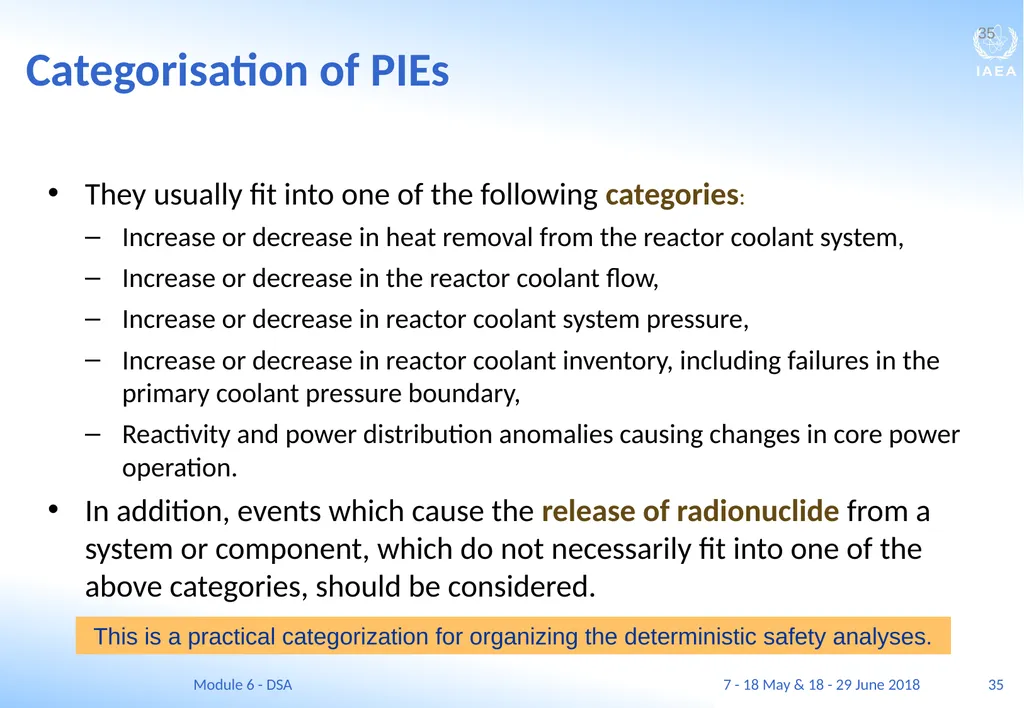
35 Categorisation of PIEs They usually fit into one of the following categories:
Increase or decrease in heat removal from the reactor coolant system,
Increase or decrease in the reactor coolant flow,
Increase or decrease in reactor coolant system pressure,
Increase or decrease in reactor coolant inventory, including failures in the primary coolant pressure boundary,
Reactivity and power distribution anomalies causing changes in core power operation.
In addition, events which cause the release of radionuclide from a system or component, which do not necessarily fit into one of the above categories, should be considered. 35 This is a practical categorization for organizing the deterministic safety analyses. 7 - 18 May & 18 - 29 June 2018 Module 6 - DSA<br>
Increase or decrease in heat removal from the reactor coolant system,
Increase or decrease in the reactor coolant flow,
Increase or decrease in reactor coolant system pressure,
Increase or decrease in reactor coolant inventory, including failures in the primary coolant pressure boundary,
Reactivity and power distribution anomalies causing changes in core power operation.
In addition, events which cause the release of radionuclide from a system or component, which do not necessarily fit into one of the above categories, should be considered. 35 This is a practical categorization for organizing the deterministic safety analyses. 7 - 18 May & 18 - 29 June 2018 Module 6 - DSA<br>
36
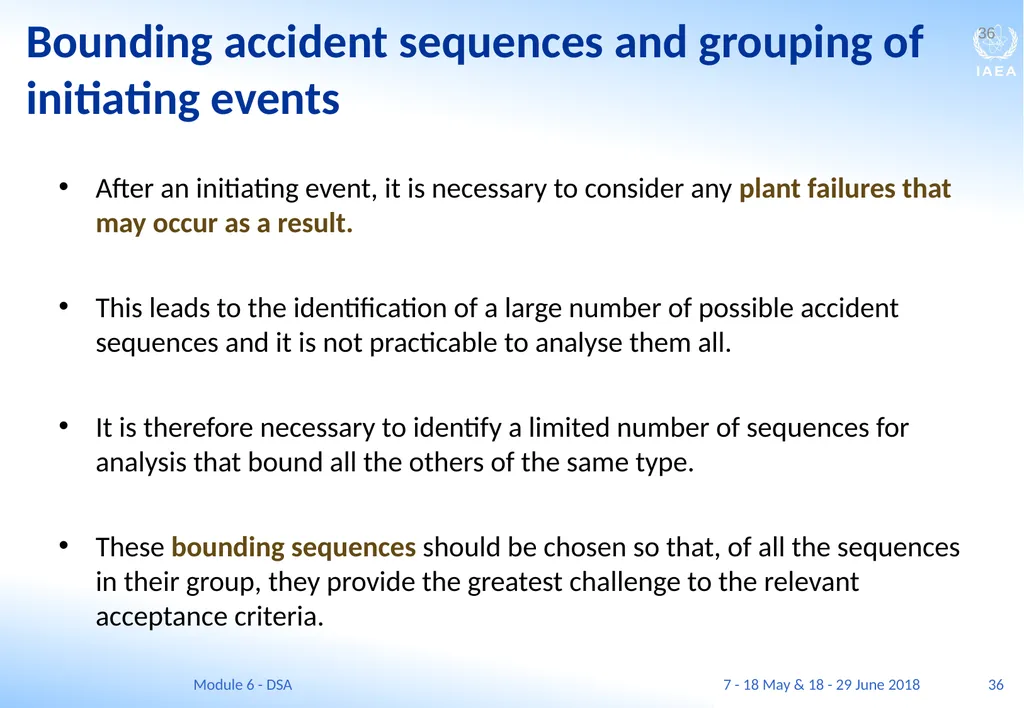
36 After an initiating event, it is necessary to consider any plant failures that may occur as a result.
This leads to the identification of a large number of possible accident sequences and it is not practicable to analyse them all.
It is therefore necessary to identify a limited number of sequences for analysis that bound all the others of the same type.
These bounding sequences should be chosen so that, of all the sequences in their group, they provide the greatest challenge to the relevant acceptance criteria. 36 Bounding accident sequences and grouping of initiating events 7 - 18 May & 18 - 29 June 2018 Module 6 - DSA<br>
This leads to the identification of a large number of possible accident sequences and it is not practicable to analyse them all.
It is therefore necessary to identify a limited number of sequences for analysis that bound all the others of the same type.
These bounding sequences should be chosen so that, of all the sequences in their group, they provide the greatest challenge to the relevant acceptance criteria. 36 Bounding accident sequences and grouping of initiating events 7 - 18 May & 18 - 29 June 2018 Module 6 - DSA<br>
37
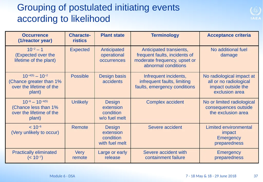
37 Grouping of postulated initiating events
according to likelihood 7 - 18 May & 18 - 29 June 2018 Module 6 - DSA<br>
38
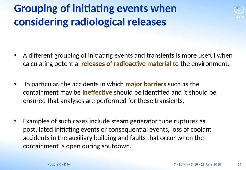
38 Grouping of initiating events when considering radiological releases A different grouping of initiating events and transients is more useful when calculating potential releases of radioactive material to the environment.
In particular, the accidents in which major barriers such as the containment may be ineffective should be identified and it should be ensured that analyses are performed for these transients.
Examples of such cases include steam generator tube ruptures as postulated initiating events or consequential events, loss of coolant accidents in the auxiliary building and faults that occur when the containment is open during shutdown. 38 7 - 18 May & 18 - 29 June 2018 Module 6 - DSA<br>
In particular, the accidents in which major barriers such as the containment may be ineffective should be identified and it should be ensured that analyses are performed for these transients.
Examples of such cases include steam generator tube ruptures as postulated initiating events or consequential events, loss of coolant accidents in the auxiliary building and faults that occur when the containment is open during shutdown. 38 7 - 18 May & 18 - 29 June 2018 Module 6 - DSA<br>
39
Acceptance criteria<br>
40
40 ACCEPTANCE CRITERIA Learning objectives
After completing this chapter, the trainee will be able to:
Describe acceptance criteria for deterministic safety analysis.
Distinguish between basic acceptance criteria and derived acceptance criteria.
State the most widely used derived acceptance criteria for the Emergency Core Cooling Systems for LWRs. 40 7 - 18 May & 18 - 29 June 2018 Module 6 - DSA<br>
After completing this chapter, the trainee will be able to:
Describe acceptance criteria for deterministic safety analysis.
Distinguish between basic acceptance criteria and derived acceptance criteria.
State the most widely used derived acceptance criteria for the Emergency Core Cooling Systems for LWRs. 40 7 - 18 May & 18 - 29 June 2018 Module 6 - DSA<br>
41
41 Basic and derived acceptance criteria Basic acceptance criteria are usually defined as the limits and conditions that must be met in order to ensure an adequate level of safety: i.e. protecting the people and the environment.
They are commonly set by a regulatory body.
These criteria are supplemented by other requirements known as acceptance criteria (sometimes termed derived acceptance criteria).
These are to ensure defence in depth by, for example, preventing the consequential failure of a pressure boundary in an accident. 41 7 - 18 May & 18 - 29 June 2018 Module 6 - DSA<br>
They are commonly set by a regulatory body.
These criteria are supplemented by other requirements known as acceptance criteria (sometimes termed derived acceptance criteria).
These are to ensure defence in depth by, for example, preventing the consequential failure of a pressure boundary in an accident. 41 7 - 18 May & 18 - 29 June 2018 Module 6 - DSA<br>
42
42 The basic acceptance criteria To demonstrate the safety of the plant, the following basic acceptance criteria should be fulfilled:
the individual doses and collective doses to workers and the public are required to be within prescribed limits and as low as reasonably achievable (ALARA principle) in all operational states by ensuring mitigation of the radiological consequences of any accident;
the integrity of barriers to the release of radioactive material (i.e. the fuel itself, the fuel cladding, the primary and/or secondary reactor coolant system, the primary and/or secondary containment) shall be maintained, depending on the categories of the plant states for the accidents for which their integrity is required. 42 7 - 18 May & 18 - 29 June 2018 Module 6 - DSA<br>
the individual doses and collective doses to workers and the public are required to be within prescribed limits and as low as reasonably achievable (ALARA principle) in all operational states by ensuring mitigation of the radiological consequences of any accident;
the integrity of barriers to the release of radioactive material (i.e. the fuel itself, the fuel cladding, the primary and/or secondary reactor coolant system, the primary and/or secondary containment) shall be maintained, depending on the categories of the plant states for the accidents for which their integrity is required. 42 7 - 18 May & 18 - 29 June 2018 Module 6 - DSA<br>
43
43 Additional basic acceptance criteria In addition:
the capabilities of systems that, and operators who, are intended to perform a safety function, directly or indirectly, should be ensured for the accidents for which performance of the safety function is required;
in state-of-the-art designs, early or large releases of radioactive material are required to be practically eliminated. 43 7 - 18 May & 18 - 29 June 2018 Module 6 - DSA<br>
the capabilities of systems that, and operators who, are intended to perform a safety function, directly or indirectly, should be ensured for the accidents for which performance of the safety function is required;
in state-of-the-art designs, early or large releases of radioactive material are required to be practically eliminated. 43 7 - 18 May & 18 - 29 June 2018 Module 6 - DSA<br>
44
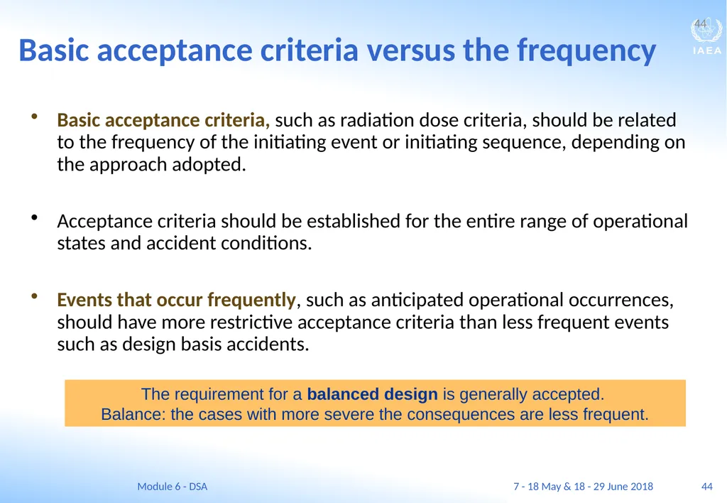
44 Basic acceptance criteria versus the frequency Basic acceptance criteria, such as radiation dose criteria, should be related to the frequency of the initiating event or initiating sequence, depending on the approach adopted.
Acceptance criteria should be established for the entire range of operational states and accident conditions.
Events that occur frequently, such as anticipated operational occurrences, should have more restrictive acceptance criteria than less frequent events such as design basis accidents. 44 The requirement for a balanced design is generally accepted. Balance: the cases with more severe the consequences are less frequent. 7 - 18 May & 18 - 29 June 2018 Module 6 - DSA<br>
Acceptance criteria should be established for the entire range of operational states and accident conditions.
Events that occur frequently, such as anticipated operational occurrences, should have more restrictive acceptance criteria than less frequent events such as design basis accidents. 44 The requirement for a balanced design is generally accepted. Balance: the cases with more severe the consequences are less frequent. 7 - 18 May & 18 - 29 June 2018 Module 6 - DSA<br>
45
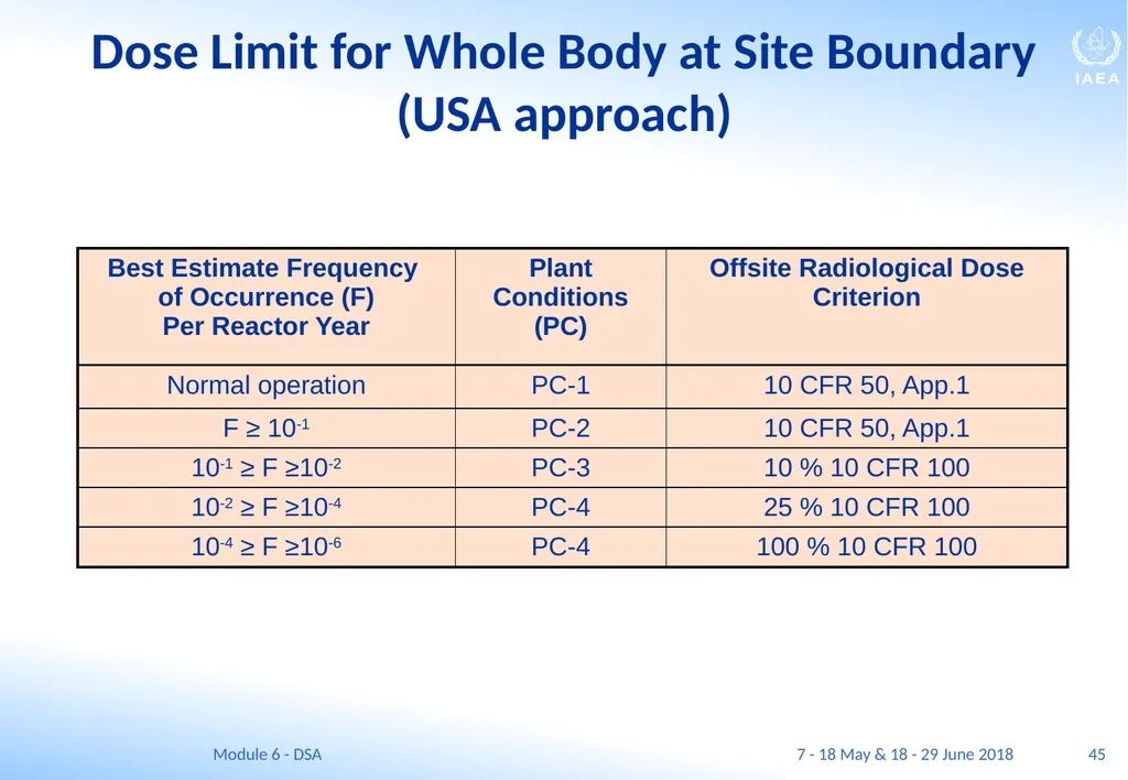
Dose Limit for Whole Body at Site Boundary (USA approach) 45 7 - 18 May & 18 - 29 June 2018 Module 6 - DSA<br>
46
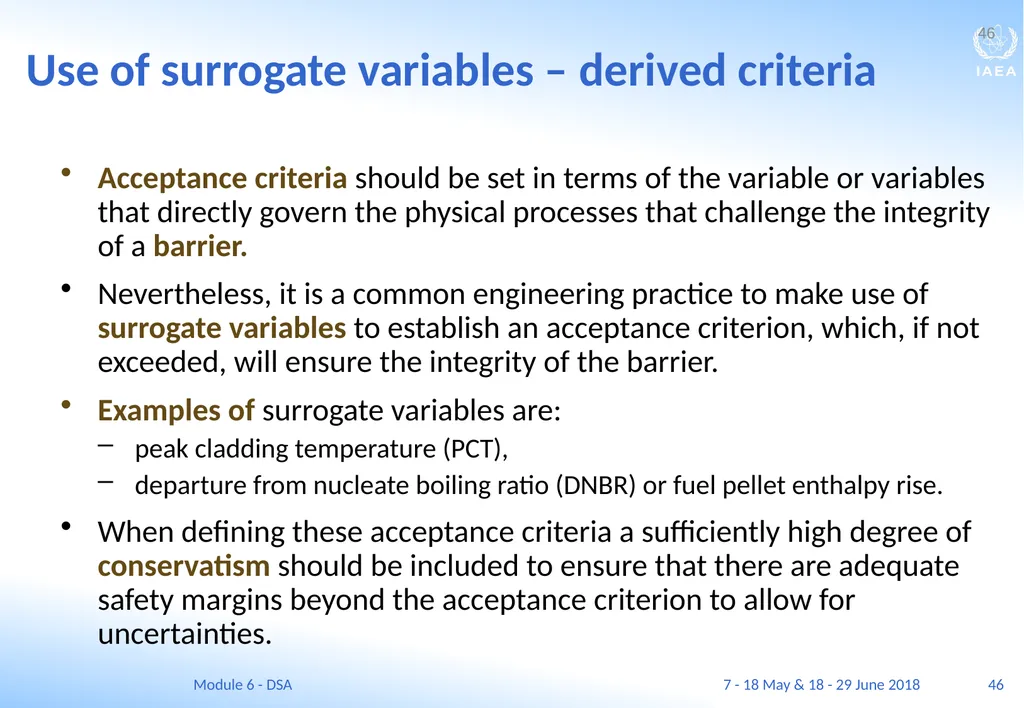
46 Use of surrogate variables – derived criteria Acceptance criteria should be set in terms of the variable or variables that directly govern the physical processes that challenge the integrity of a barrier.
Nevertheless, it is a common engineering practice to make use of surrogate variables to establish an acceptance criterion, which, if not exceeded, will ensure the integrity of the barrier.
Examples of surrogate variables are:
peak cladding temperature (PCT),
departure from nucleate boiling ratio (DNBR) or fuel pellet enthalpy rise.
When defining these acceptance criteria a sufficiently high degree of conservatism should be included to ensure that there are adequate safety margins beyond the acceptance criterion to allow for uncertainties. 46 7 - 18 May & 18 - 29 June 2018 Module 6 - DSA<br>
Nevertheless, it is a common engineering practice to make use of surrogate variables to establish an acceptance criterion, which, if not exceeded, will ensure the integrity of the barrier.
Examples of surrogate variables are:
peak cladding temperature (PCT),
departure from nucleate boiling ratio (DNBR) or fuel pellet enthalpy rise.
When defining these acceptance criteria a sufficiently high degree of conservatism should be included to ensure that there are adequate safety margins beyond the acceptance criterion to allow for uncertainties. 46 7 - 18 May & 18 - 29 June 2018 Module 6 - DSA<br>
47
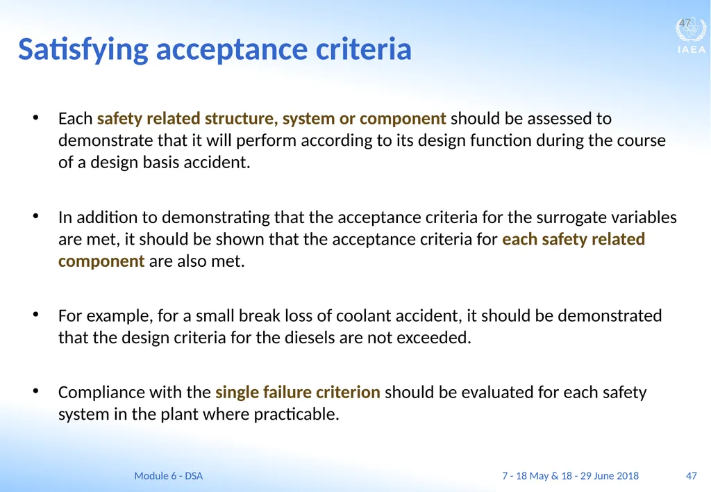
47 Satisfying acceptance criteria Each safety related structure, system or component should be assessed to demonstrate that it will perform according to its design function during the course of a design basis accident.
In addition to demonstrating that the acceptance criteria for the surrogate variables are met, it should be shown that the acceptance criteria for each safety related component are also met.
For example, for a small break loss of coolant accident, it should be demonstrated that the design criteria for the diesels are not exceeded.
Compliance with the single failure criterion should be evaluated for each safety system in the plant where practicable. 47 7 - 18 May & 18 - 29 June 2018 Module 6 - DSA<br>
In addition to demonstrating that the acceptance criteria for the surrogate variables are met, it should be shown that the acceptance criteria for each safety related component are also met.
For example, for a small break loss of coolant accident, it should be demonstrated that the design criteria for the diesels are not exceeded.
Compliance with the single failure criterion should be evaluated for each safety system in the plant where practicable. 47 7 - 18 May & 18 - 29 June 2018 Module 6 - DSA<br>
48
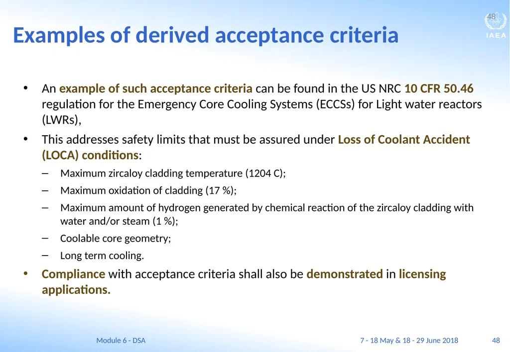
48 Examples of derived acceptance criteria An example of such acceptance criteria can be found in the US NRC 10 CFR 50.46 regulation for the Emergency Core Cooling Systems (ECCSs) for Light water reactors (LWRs),
This addresses safety limits that must be assured under Loss of Coolant Accident (LOCA) conditions:
Maximum zircaloy cladding temperature (1204 C);
Maximum oxidation of cladding (17 %);
Maximum amount of hydrogen generated by chemical reaction of the zircaloy cladding with water and/or steam (1 %);
Coolable core geometry;
Long term cooling.
Compliance with acceptance criteria shall also be demonstrated in licensing applications. 48 7 - 18 May & 18 - 29 June 2018 Module 6 - DSA<br>
This addresses safety limits that must be assured under Loss of Coolant Accident (LOCA) conditions:
Maximum zircaloy cladding temperature (1204 C);
Maximum oxidation of cladding (17 %);
Maximum amount of hydrogen generated by chemical reaction of the zircaloy cladding with water and/or steam (1 %);
Coolable core geometry;
Long term cooling.
Compliance with acceptance criteria shall also be demonstrated in licensing applications. 48 7 - 18 May & 18 - 29 June 2018 Module 6 - DSA<br>
49
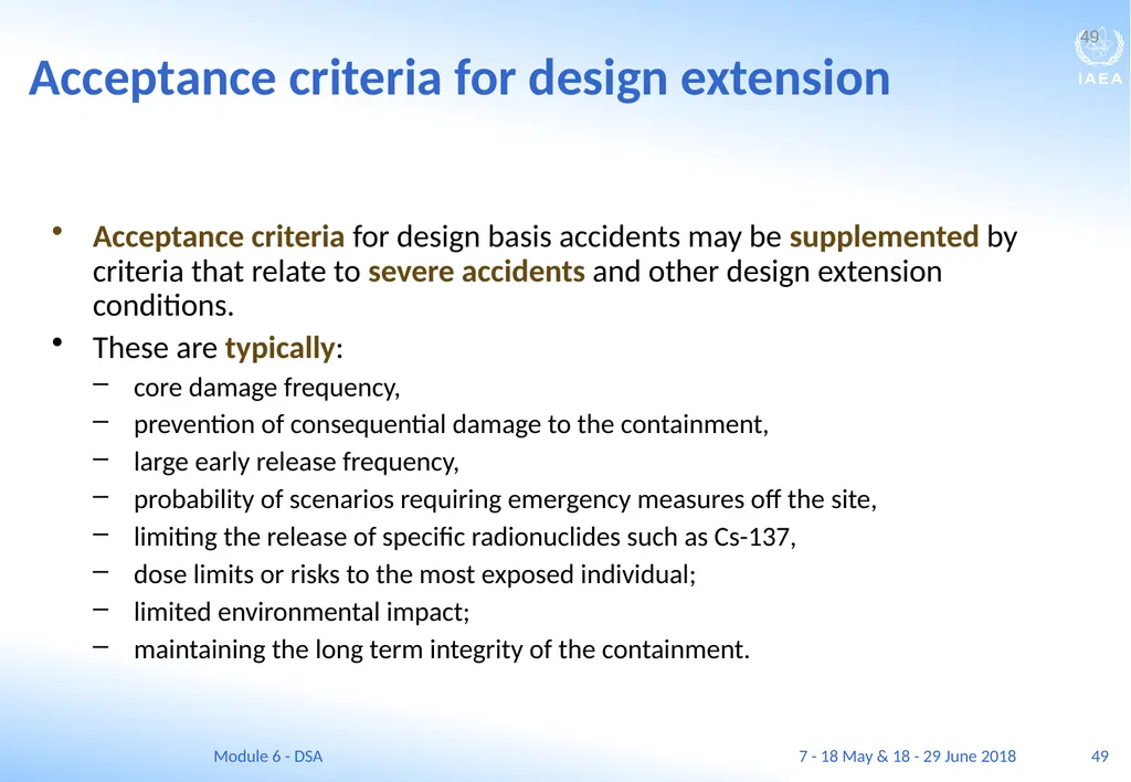
49 Acceptance criteria for design extension Acceptance criteria for design basis accidents may be supplemented by criteria that relate to severe accidents and other design extension conditions.
These are typically:
core damage frequency,
prevention of consequential damage to the containment,
large early release frequency,
probability of scenarios requiring emergency measures off the site,
limiting the release of specific radionuclides such as Cs-137,
dose limits or risks to the most exposed individual;
limited environmental impact;
maintaining the long term integrity of the containment. 49 7 - 18 May & 18 - 29 June 2018 Module 6 - DSA<br>
These are typically:
core damage frequency,
prevention of consequential damage to the containment,
large early release frequency,
probability of scenarios requiring emergency measures off the site,
limiting the release of specific radionuclides such as Cs-137,
dose limits or risks to the most exposed individual;
limited environmental impact;
maintaining the long term integrity of the containment. 49 7 - 18 May & 18 - 29 June 2018 Module 6 - DSA<br>
50
Types of deterministic analyses<br>
51
51 TYPES OF DETERMINISTIC SAFETY ANALYSES Learning objectives
After completing this chapter, the trainee will be able to:
List 4 options available for deterministic calculations.
Distinguish between conservative and best estimate calculations.
Describe the difference between determination of availability of safety systems in conservative and PSA based option. 51 7 - 18 May & 18 - 29 June 2018 Module 6 - DSA<br>
After completing this chapter, the trainee will be able to:
List 4 options available for deterministic calculations.
Distinguish between conservative and best estimate calculations.
Describe the difference between determination of availability of safety systems in conservative and PSA based option. 51 7 - 18 May & 18 - 29 June 2018 Module 6 - DSA<br>
52
52 Nature of deterministic safety analyses Deterministic safety analyses are calculations that are performed to describe the behaviour of the plant under a given set of conditions.
These conditions include:
the physical description of the nuclear power plant or relevant parts of it,
equations that describe the relevant phenomena,
information about the properties of the materials and equipment,
a set of initial conditions, including the PIE in question. 52 7 - 18 May & 18 - 29 June 2018 Module 6 - DSA<br>
These conditions include:
the physical description of the nuclear power plant or relevant parts of it,
equations that describe the relevant phenomena,
information about the properties of the materials and equipment,
a set of initial conditions, including the PIE in question. 52 7 - 18 May & 18 - 29 June 2018 Module 6 - DSA<br>
53
53 Types of deterministic safety analyses For a nuclear power plant, the analysis may include
neutronics,
reactor dynamics,
radiation shielding,
steady state and transient thermal-hydraulics,
heat transfer in the core and in various components,
fuel behaviour, and
structural statics and dynamics.
A number of computer codes are used to perform the calculations.
These codes, the analytical models used, and the plant descriptive models must be verified and validated, and accepted for their particular application. 53 7 - 18 May & 18 - 29 June 2018 Module 6 - DSA<br>
neutronics,
reactor dynamics,
radiation shielding,
steady state and transient thermal-hydraulics,
heat transfer in the core and in various components,
fuel behaviour, and
structural statics and dynamics.
A number of computer codes are used to perform the calculations.
These codes, the analytical models used, and the plant descriptive models must be verified and validated, and accepted for their particular application. 53 7 - 18 May & 18 - 29 June 2018 Module 6 - DSA<br>
54
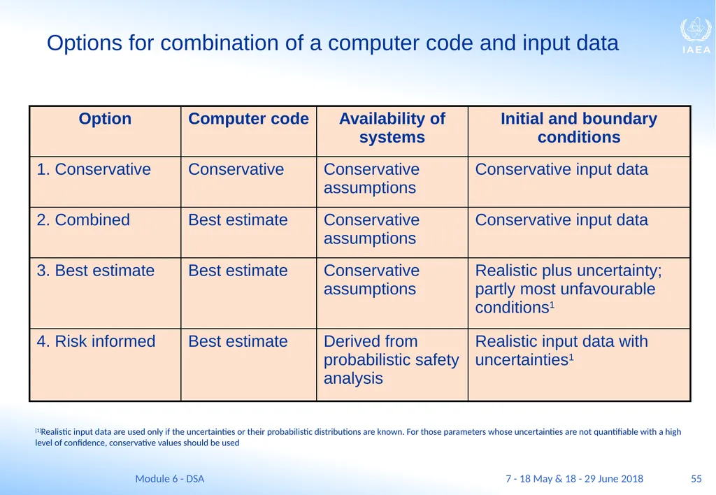
54 Approaches of deterministic safety analyses There are three alternative ways of analysing anticipated operational occurrences and design basis accidents to demonstrate that the safety requirements are met:
Use of conservative computer codes with conservative initial and boundary conditions (conservative analysis);
Use of best estimate computer codes combined with conservative initial and boundary conditions (combined analysis);
Use of best estimate computer codes with conservative and/or realistic input data but coupled with an evaluation of the uncertainties of the results. A conservative value of the relevant parameter, which takes into account the quantified level of uncertainty, is used in the safety evaluation. 54 7 - 18 May & 18 - 29 June 2018 Module 6 - DSA<br>
Use of conservative computer codes with conservative initial and boundary conditions (conservative analysis);
Use of best estimate computer codes combined with conservative initial and boundary conditions (combined analysis);
Use of best estimate computer codes with conservative and/or realistic input data but coupled with an evaluation of the uncertainties of the results. A conservative value of the relevant parameter, which takes into account the quantified level of uncertainty, is used in the safety evaluation. 54 7 - 18 May & 18 - 29 June 2018 Module 6 - DSA<br>
55
55 Options for combination of a computer code and input data [1]Realistic input data are used only if the uncertainties or their probabilistic distributions are known. For those parameters whose uncertainties are not quantifiable with a high level of confidence, conservative values should be used 7 - 18 May & 18 - 29 June 2018 Module 6 - DSA<br>
56
56 Types of deterministic safety analyses In the early period of the nuclear industry (from 1960-1990), AOOs and DBAs were analysed using conservative input data and conservative codes that contained simplified and conservative models.
This was mainly because of the difficulty in modelling complicated physical phenomena with a limited computer capacity and the lack of adequate data.
As more experimental data become available and the capability of computer codes advanced, the practice in many Member States has moved towards a more realistic approach together with an evaluation of uncertainties.
This is termed a best estimate approach. It has been particularly applied to the analysis of loss of coolant accidents (LOCAs). 56 7 - 18 May & 18 - 29 June 2018 Module 6 - DSA<br>
This was mainly because of the difficulty in modelling complicated physical phenomena with a limited computer capacity and the lack of adequate data.
As more experimental data become available and the capability of computer codes advanced, the practice in many Member States has moved towards a more realistic approach together with an evaluation of uncertainties.
This is termed a best estimate approach. It has been particularly applied to the analysis of loss of coolant accidents (LOCAs). 56 7 - 18 May & 18 - 29 June 2018 Module 6 - DSA<br>
57
57 Reasons for best estimate deterministic safety analyses The use of best estimate analysis together with an evaluation of the uncertainties is increasing for the following reasons:
The use of conservative assumptions may sometimes lead to the prediction of an incorrect progression of events or unrealistic timescales, or it may not include some important physical phenomena. The sequences of events that constitute the accident scenario, which are important in assessing the safety of the plant, may thus be overlooked;
The use of a conservative approach often does not show the margins to the acceptance criteria that apply in reality and which could be taken into account to improve operational flexibility; 57 7 - 18 May & 18 - 29 June 2018 Module 6 - DSA<br>
The use of conservative assumptions may sometimes lead to the prediction of an incorrect progression of events or unrealistic timescales, or it may not include some important physical phenomena. The sequences of events that constitute the accident scenario, which are important in assessing the safety of the plant, may thus be overlooked;
The use of a conservative approach often does not show the margins to the acceptance criteria that apply in reality and which could be taken into account to improve operational flexibility; 57 7 - 18 May & 18 - 29 June 2018 Module 6 - DSA<br>
58
58 Reasons for best estimate deterministic safety analyses In addition:
A best estimate approach provides more realistic information about the physical behaviour of the plant, assists in identifying the most relevant safety parameters, and allows more a realistic comparison with acceptance criteria;
For anticipated operational occurrences, the use of a best estimate approach together with an evaluation of the uncertainties may avoid selecting unnecessarily restrictive limits and set points. In turn, this may provide additional operational flexibility and reduce unnecessary reactor scrams or actuations of the protection systems. 58 7 - 18 May & 18 - 29 June 2018 Module 6 - DSA<br>
A best estimate approach provides more realistic information about the physical behaviour of the plant, assists in identifying the most relevant safety parameters, and allows more a realistic comparison with acceptance criteria;
For anticipated operational occurrences, the use of a best estimate approach together with an evaluation of the uncertainties may avoid selecting unnecessarily restrictive limits and set points. In turn, this may provide additional operational flexibility and reduce unnecessary reactor scrams or actuations of the protection systems. 58 7 - 18 May & 18 - 29 June 2018 Module 6 - DSA<br>
59
59 Use of deterministic safety analyses for design extension conditions For analysing design extension conditions typically best estimate calculations are applied in many States.
This is because of limited availability of data for these infrequent events; a thorough uncertainty analysis is hardly possible for these sequences.
However, the range of uncertainties associated with the relevant phenomena should be taken into account when determining what actions should be taken and what design features should be incorporated to prevent:
the core melting,
failure of the reactor pressure vessel or
failure of the containment. 59 7 - 18 May & 18 - 29 June 2018 Module 6 - DSA<br>
This is because of limited availability of data for these infrequent events; a thorough uncertainty analysis is hardly possible for these sequences.
However, the range of uncertainties associated with the relevant phenomena should be taken into account when determining what actions should be taken and what design features should be incorporated to prevent:
the core melting,
failure of the reactor pressure vessel or
failure of the containment. 59 7 - 18 May & 18 - 29 June 2018 Module 6 - DSA<br>
60
60 The use of Option 4 for deterministic safety analyses Option 4 is not yet widely used.
It is an attempt to combine insights from probabilistic safety analyses with a deterministic approach, which results in a risk informed safety analysis.
In Options 1 – 3, the availability of safety systems is based on conservative assumptions whereas, in Option 4, the availability of safety systems is derived by probabilistic means. 60 7 - 18 May & 18 - 29 June 2018 Module 6 - DSA<br>
It is an attempt to combine insights from probabilistic safety analyses with a deterministic approach, which results in a risk informed safety analysis.
In Options 1 – 3, the availability of safety systems is based on conservative assumptions whereas, in Option 4, the availability of safety systems is derived by probabilistic means. 60 7 - 18 May & 18 - 29 June 2018 Module 6 - DSA<br>
61
Conservative deterministic safety analysis<br>
62
62 CONSERVATIVE DETERMINISTIC SAFETY ANALYSIS Learning objectives
After completing this chapter, the trainee will be able to:
Describe the purpose of conservative deterministic safety analysis.
Describe initial and boundary conditions used in deterministic safety analyses.
Explain the importance of the single failure criterion.
Describe the technique of NPP nodalization used in deterministic calculations. 62 7 - 18 May & 18 - 29 June 2018 Module 6 - DSA<br>
After completing this chapter, the trainee will be able to:
Describe the purpose of conservative deterministic safety analysis.
Describe initial and boundary conditions used in deterministic safety analyses.
Explain the importance of the single failure criterion.
Describe the technique of NPP nodalization used in deterministic calculations. 62 7 - 18 May & 18 - 29 June 2018 Module 6 - DSA<br>
63
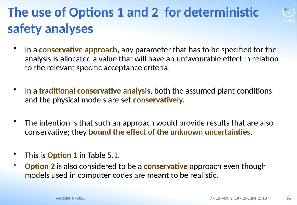
63 The use of Options 1 and 2 for deterministic safety analyses In a conservative approach, any parameter that has to be specified for the analysis is allocated a value that will have an unfavourable effect in relation to the relevant specific acceptance criteria.
In a traditional conservative analysis, both the assumed plant conditions and the physical models are set conservatively.
The intention is that such an approach would provide results that are also conservative; they bound the effect of the unknown uncertainties.
This is Option 1 in Table 5.1.
Option 2 is also considered to be a conservative approach even though models used in computer codes are meant to be realistic. 63 7 - 18 May & 18 - 29 June 2018 Module 6 - DSA<br>
In a traditional conservative analysis, both the assumed plant conditions and the physical models are set conservatively.
The intention is that such an approach would provide results that are also conservative; they bound the effect of the unknown uncertainties.
This is Option 1 in Table 5.1.
Option 2 is also considered to be a conservative approach even though models used in computer codes are meant to be realistic. 63 7 - 18 May & 18 - 29 June 2018 Module 6 - DSA<br>
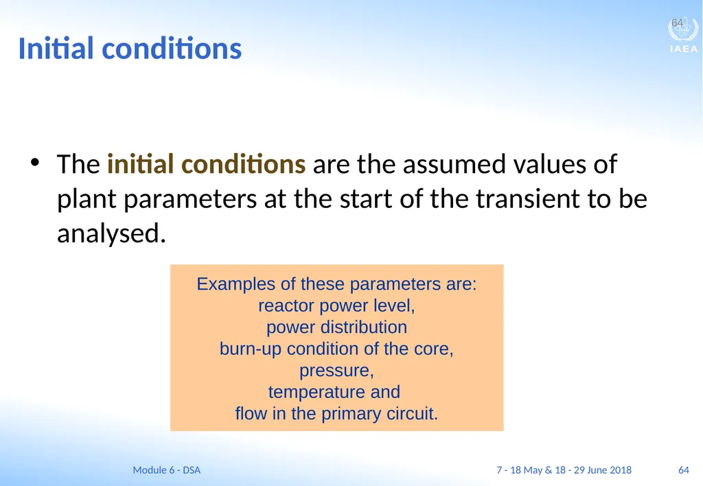
64
64 Initial conditions The initial conditions are the assumed values of plant parameters at the start of the transient to be analysed. 64 Examples of these parameters are:
reactor power level,
power distribution
burn-up condition of the core,
pressure,
temperature and
flow in the primary circuit. 7 - 18 May & 18 - 29 June 2018 Module 6 - DSA<br>
reactor power level,
power distribution
burn-up condition of the core,
pressure,
temperature and
flow in the primary circuit. 7 - 18 May & 18 - 29 June 2018 Module 6 - DSA<br>
65
65 Boundary conditions The boundary conditions are the assumed values of parameters throughout the transient. 65 Examples of boundary conditions are:
the actuation time of safety systems
such as pumps and power supplies,
leading to changes in flow rates,
and external sources and sinks for mass and energy. 7 - 18 May & 18 - 29 June 2018 Module 6 - DSA<br>
the actuation time of safety systems
such as pumps and power supplies,
leading to changes in flow rates,
and external sources and sinks for mass and energy. 7 - 18 May & 18 - 29 June 2018 Module 6 - DSA<br>
66
66 Setting initial and boundary conditions For the purpose of conservative calculations, the initial and boundary conditions should be set to values that will lead to conservative results for those safety parameters that are to be compared with the acceptance criteria.
A single set of conservative values for initial and boundary conditions may not necessarily lead to conservative results for every safety parameter.
Therefore, the appropriate conservatism should be selected for each initial and boundary condition, depending on the specific transient and the associated acceptance criterion. 66 7 - 18 May & 18 - 29 June 2018 Module 6 - DSA<br>
A single set of conservative values for initial and boundary conditions may not necessarily lead to conservative results for every safety parameter.
Therefore, the appropriate conservatism should be selected for each initial and boundary condition, depending on the specific transient and the associated acceptance criterion. 66 7 - 18 May & 18 - 29 June 2018 Module 6 - DSA<br>
67
67 The single failure criterion In conservative analyses, the single failure criterion should be applied when determining the availability of systems and components.
In view of their importance, safety systems that are required during AOOs or accidents must have a very high level of reliability.
For the design of safety systems, the single failure criterion means that safety related systems must be able to fulfil their function in an adequate manner even in the case of failure of any one of their components.
For safety analyses, a failure shall be assumed in the system or component that would have the largest negative effect on the calculated safety parameters. 67 7 - 18 May & 18 - 29 June 2018 Module 6 - DSA<br>
In view of their importance, safety systems that are required during AOOs or accidents must have a very high level of reliability.
For the design of safety systems, the single failure criterion means that safety related systems must be able to fulfil their function in an adequate manner even in the case of failure of any one of their components.
For safety analyses, a failure shall be assumed in the system or component that would have the largest negative effect on the calculated safety parameters. 67 7 - 18 May & 18 - 29 June 2018 Module 6 - DSA<br>
68
68 Operator action For design purposes, credit should not be taken for operator action to limit the evolution of a design basis accident or Anticipated Operational Occurrence within a specified time.
Exceptionally, the design may take credit for earlier operator action but, in these cases, the actuation times should be conservative and should be fully justified.
Conservative assumptions should be made with respect to the timing of operator actions.
However, it should be assumed that, in most cases, post-accident recovery actions would be taken by the operator. 68 7 - 18 May & 18 - 29 June 2018 Module 6 - DSA<br>
Exceptionally, the design may take credit for earlier operator action but, in these cases, the actuation times should be conservative and should be fully justified.
Conservative assumptions should be made with respect to the timing of operator actions.
However, it should be assumed that, in most cases, post-accident recovery actions would be taken by the operator. 68 7 - 18 May & 18 - 29 June 2018 Module 6 - DSA<br>
69
69 Nodalization, plant modelling and large break LOCA analysis In a thermal-hydraulic code (as well as for any other analysis code), the plant is described in terms of discrete volumes or nodes.
Normally, but not always, the more nodes that are used, the more accurate is the representation of the plant.
However with the increased number of nodes, the time to perform the calculation also increases.
In some cases, the results produced by an analysis are sensitive to decisions made by the user about the number and structure of nodes that are used. This is called as user effect. 69 7 - 18 May & 18 - 29 June 2018 Module 6 - DSA<br>
Normally, but not always, the more nodes that are used, the more accurate is the representation of the plant.
However with the increased number of nodes, the time to perform the calculation also increases.
In some cases, the results produced by an analysis are sensitive to decisions made by the user about the number and structure of nodes that are used. This is called as user effect. 69 7 - 18 May & 18 - 29 June 2018 Module 6 - DSA<br>
70
70 Nodalization, plant modelling and large break LOCA analysis Over the years, the DBA that has drawn the most attention is the large-break loss-of-coolant accident (LBLOCA) and its historical analysis typifies the conservative approach.
This accident is the limiting design basis accident for the emergency core cooling systems (ECCS) and the containment building for most of the current fleet of light-water reactors.
In the USA, the RELAP5 and TRAC codes were both developed under auspices of the USNRC to analyse this DBA, and the RETRAN code was developed by EPRI for utility use.
In addition, the reactor designers have their own proprietary codes. 70 7 - 18 May & 18 - 29 June 2018 Module 6 - DSA<br>
This accident is the limiting design basis accident for the emergency core cooling systems (ECCS) and the containment building for most of the current fleet of light-water reactors.
In the USA, the RELAP5 and TRAC codes were both developed under auspices of the USNRC to analyse this DBA, and the RETRAN code was developed by EPRI for utility use.
In addition, the reactor designers have their own proprietary codes. 70 7 - 18 May & 18 - 29 June 2018 Module 6 - DSA<br>
71
71 Plant modelling and large break LOCA analysis Development of the codes was supported by numerous experiments, among them being the loss-of-fluid tests (LOFT) and semi-scale experiments conducted in the 1970s and 1980s.
The analysis includes consideration of blowdown of the primary system following the postulated pipe break, followed by re-flooding of the core by the ECCS, and finally long-term cooling by recirculation of water within the containment.
The deterministic analysis is aimed at showing compliance with limits of a maximum cladding temperature of 1204 C and a maximum oxidation of less than 17% of the cladding thickness.
The LBLOCA analysis is a classical illustration of deterministic safety analysis. 71 7 - 18 May & 18 - 29 June 2018 Module 6 - DSA<br>
The analysis includes consideration of blowdown of the primary system following the postulated pipe break, followed by re-flooding of the core by the ECCS, and finally long-term cooling by recirculation of water within the containment.
The deterministic analysis is aimed at showing compliance with limits of a maximum cladding temperature of 1204 C and a maximum oxidation of less than 17% of the cladding thickness.
The LBLOCA analysis is a classical illustration of deterministic safety analysis. 71 7 - 18 May & 18 - 29 June 2018 Module 6 - DSA<br>
72
Best estimate plus uncertainty analysis - BEPU<br>
73
73 BEST ESTIMATE PLUS UNCERTAINTY (BEPU) ANALYSIS Learning objectives
After completing this chapter, the trainee will be able to:
Describe the use of best estimate approach.
Describe the general methodology for determining the uncertainty of the safety analysis.
Describe the concept of safety margins. 73 7 - 18 May & 18 - 29 June 2018 Module 6 - DSA<br>
After completing this chapter, the trainee will be able to:
Describe the use of best estimate approach.
Describe the general methodology for determining the uncertainty of the safety analysis.
Describe the concept of safety margins. 73 7 - 18 May & 18 - 29 June 2018 Module 6 - DSA<br>
74
74 Best estimate approach The disadvantages of using a conservative approach have been described earlier.
In addition, it is not always easy to determine what assumptions will lead to a conservative result and, thus, some calculations that were thought to be conservative might not be.
For example, the assumption of a high core power level may lead to high levels of the steam–water mixture in the core in the case of a postulated small break loss of coolant accident (SBLOCA).
Consequently, the calculated peak cladding temperature may not be conservative. 74 7 - 18 May & 18 - 29 June 2018 Module 6 - DSA<br>
In addition, it is not always easy to determine what assumptions will lead to a conservative result and, thus, some calculations that were thought to be conservative might not be.
For example, the assumption of a high core power level may lead to high levels of the steam–water mixture in the core in the case of a postulated small break loss of coolant accident (SBLOCA).
Consequently, the calculated peak cladding temperature may not be conservative. 74 7 - 18 May & 18 - 29 June 2018 Module 6 - DSA<br>
75
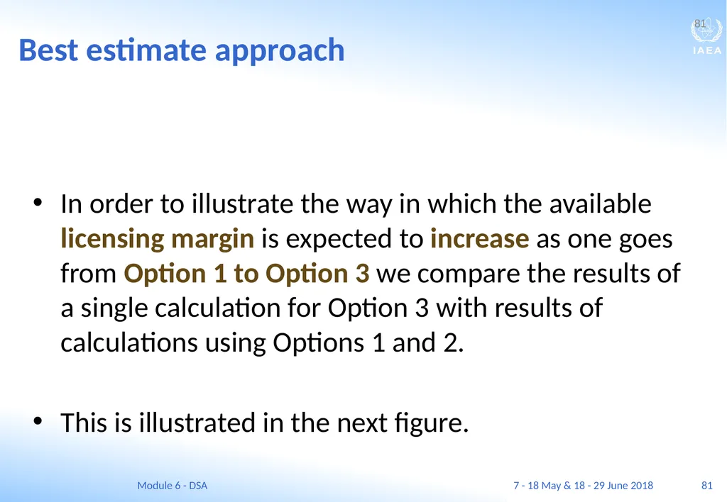
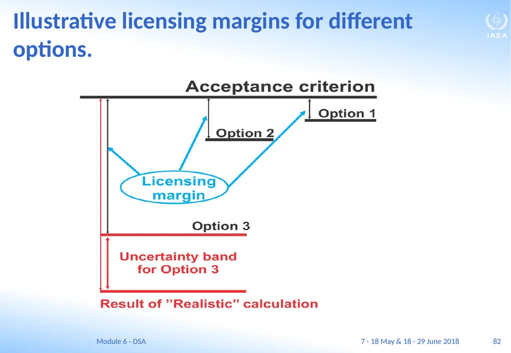
75 Best estimate approach To overcome these deficiencies, it may be preferable to use a best estimate approach together with an evaluation of the uncertainties to compare the results of calculations with acceptance criteria.
This type of analysis is referred to as a best estimate plus uncertainties (BEPU) approach and is Option 3 in Table 5.1.
A best estimate approach provides:
more realistic information about the physical behaviour of the reactor and the technology,
identifies the most relevant safety issues and
provides reliable information about the existing margins between the results of calculations and the acceptance criteria (which can be utilized for example to produce more power). 75 7 - 18 May & 18 - 29 June 2018 Module 6 - DSA<br>
This type of analysis is referred to as a best estimate plus uncertainties (BEPU) approach and is Option 3 in Table 5.1.
A best estimate approach provides:
more realistic information about the physical behaviour of the reactor and the technology,
identifies the most relevant safety issues and
provides reliable information about the existing margins between the results of calculations and the acceptance criteria (which can be utilized for example to produce more power). 75 7 - 18 May & 18 - 29 June 2018 Module 6 - DSA<br>
76
76 Best estimate approach For a best estimate analysis, a best estimate code is used that realistically describe the behaviour of physical processes in a component or system.
This requires sufficient and accurate data to be able to ensure that all the important phenomena have been taken into account in the modelling or that their effects are bounded.
The validation programme shall ensure that all the important phenomena are taken into account in the modelling or that their effects are bounded.
Uncertainties in the results due to unavoidable approximations in the modelling should be quantified (or bounded) using experimental results. 76 7 - 18 May & 18 - 29 June 2018 Module 6 - DSA<br>
This requires sufficient and accurate data to be able to ensure that all the important phenomena have been taken into account in the modelling or that their effects are bounded.
The validation programme shall ensure that all the important phenomena are taken into account in the modelling or that their effects are bounded.
Uncertainties in the results due to unavoidable approximations in the modelling should be quantified (or bounded) using experimental results. 76 7 - 18 May & 18 - 29 June 2018 Module 6 - DSA<br>
77
77 Best estimate approach In order to establish the effect of uncertainties, it is necessary to perform a number of computer runs when the critical parameters shall be varied randomly in accordance with their respective probability distributions to determine the uncertainty.
The overall uncertainty is based on statistical combination of the uncertainties due to different plant conditions and due to model approximations in order to to establish, with a specified high probability, that the calculated results do not exceed the acceptance criteria. 77 7 - 18 May & 18 - 29 June 2018 Module 6 - DSA<br>
The overall uncertainty is based on statistical combination of the uncertainties due to different plant conditions and due to model approximations in order to to establish, with a specified high probability, that the calculated results do not exceed the acceptance criteria. 77 7 - 18 May & 18 - 29 June 2018 Module 6 - DSA<br>
78
78 Best estimate approach It is common practice that assurance has to be provided that the applicable acceptance criteria for a plant will not be exceeded with a probability of 95 % or more.
Techniques may be applied that use additional confidence levels, e.g. 95 % confidence levels, with account taken of the possible sampling error due to the fact that a limited number of calculations have been performed.
This leads to the so called (95/95) results, meaning with 95 % probability and with 95 % confidence level. 78 7 - 18 May & 18 - 29 June 2018 Module 6 - DSA<br>
Techniques may be applied that use additional confidence levels, e.g. 95 % confidence levels, with account taken of the possible sampling error due to the fact that a limited number of calculations have been performed.
This leads to the so called (95/95) results, meaning with 95 % probability and with 95 % confidence level. 78 7 - 18 May & 18 - 29 June 2018 Module 6 - DSA<br>
79
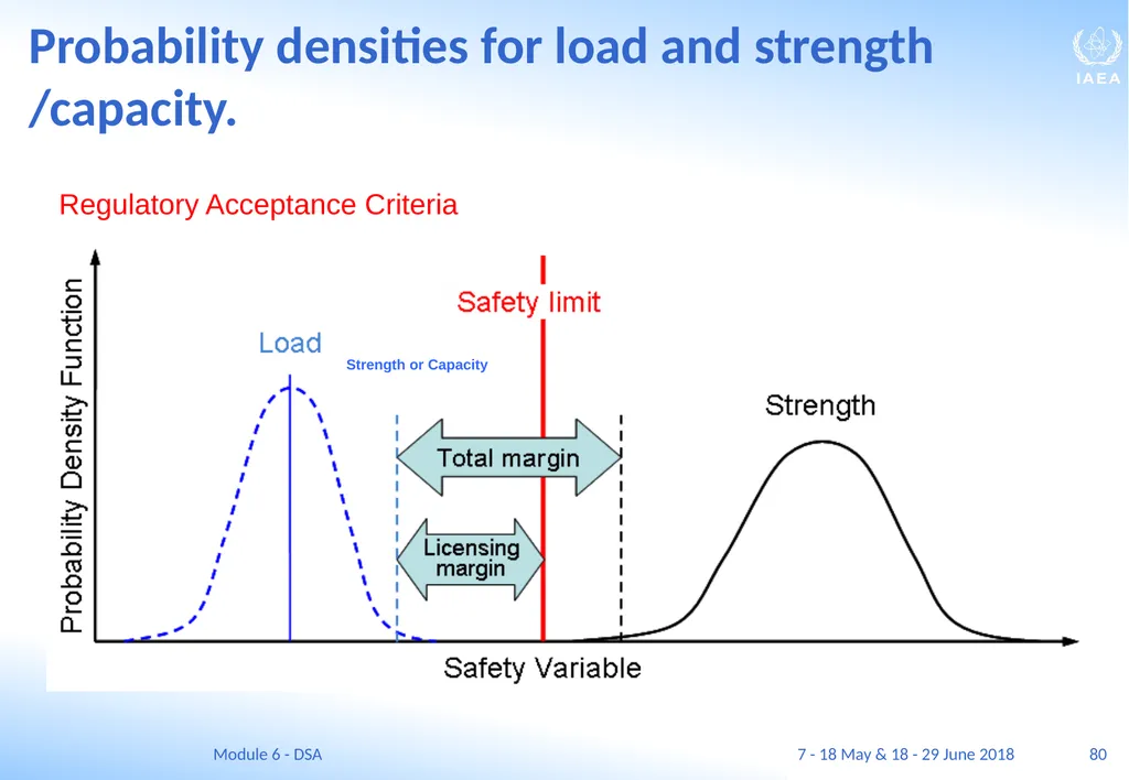
79 Best estimate approach Using a Best Estimate plus Uncertainty (BEPU) approach leads to the distribution of code predictions/results for the most limiting value of the safety variable (for example the peak cladding temperature during transient).
This distribution is a consequence of uncertainties in the initial and boundary conditions as well as in the computer model.
On the other hand, a distribution of failures is a consequence of the fact that failures are random and our knowledge is limited about the precise phenomena that can cause failures.
Assuming that both distributions (of code predictions and of actual failures) follow a Gaussian distribution leads us to the concept of licensing margin as illustrated in the next slide. 79 7 - 18 May & 18 - 29 June 2018 Module 6 - DSA<br>
This distribution is a consequence of uncertainties in the initial and boundary conditions as well as in the computer model.
On the other hand, a distribution of failures is a consequence of the fact that failures are random and our knowledge is limited about the precise phenomena that can cause failures.
Assuming that both distributions (of code predictions and of actual failures) follow a Gaussian distribution leads us to the concept of licensing margin as illustrated in the next slide. 79 7 - 18 May & 18 - 29 June 2018 Module 6 - DSA<br>
80
80 Probability densities for load and strength /capacity. Regulatory Acceptance Criteria Strength or Capacity 7 - 18 May & 18 - 29 June 2018 Module 6 - DSA<br>
81
81 Best estimate approach In order to illustrate the way in which the available licensing margin is expected to increase as one goes from Option 1 to Option 3 we compare the results of a single calculation for Option 3 with results of calculations using Options 1 and 2.
This is illustrated in the next figure. 81 7 - 18 May & 18 - 29 June 2018 Module 6 - DSA<br>
This is illustrated in the next figure. 81 7 - 18 May & 18 - 29 June 2018 Module 6 - DSA<br>
82
82 Illustrative licensing margins for different options. 7 - 18 May & 18 - 29 June 2018 Module 6 - DSA<br>
83
Sensitivity and uncertainty analysis<br>
84
84 SENSITIVITY AND UNCERTAINTY ANALYSIS Learning objectives
After completing this chapter, the trainee will be able to:
Distinguish between sensitivity and uncertainty analyses.
Explain the importance of performing uncertainty and sensitivity analyses.
Distinguish between epistemic and aleatory uncertainties. 84 7 - 18 May & 18 - 29 June 2018 Module 6 - DSA<br>
After completing this chapter, the trainee will be able to:
Distinguish between sensitivity and uncertainty analyses.
Explain the importance of performing uncertainty and sensitivity analyses.
Distinguish between epistemic and aleatory uncertainties. 84 7 - 18 May & 18 - 29 June 2018 Module 6 - DSA<br>
85
85 Sensitivity and uncertainty analysis The goal of sensitivity analysis is to determine the sensitivity of the analysis results against specific input parameters. This is done by systematic variation of each of the selected individual code input variable within its range of uncertainty, to determine its influence on the results of the calculation.
An uncertainty analysis addresses the uncertainties in the code models, in the plant model and in the plant data, including uncertainties in measurements and uncertainties in calibration, for the analysis of each individual event.
The overall uncertainty in the results of a calculation should be obtained by combining the uncertainties associated with each individual input. 85 7 - 18 May & 18 - 29 June 2018 Module 6 - DSA<br>
An uncertainty analysis addresses the uncertainties in the code models, in the plant model and in the plant data, including uncertainties in measurements and uncertainties in calibration, for the analysis of each individual event.
The overall uncertainty in the results of a calculation should be obtained by combining the uncertainties associated with each individual input. 85 7 - 18 May & 18 - 29 June 2018 Module 6 - DSA<br>
86
86 Two kinds of uncertainty of input parameters Two different kinds of uncertainties, epistemic uncertainties and aleatory uncertainties should be distinguished.
They should be treated separately. 86 7 - 18 May & 18 - 29 June 2018 Module 6 - DSA<br>
They should be treated separately. 86 7 - 18 May & 18 - 29 June 2018 Module 6 - DSA<br>
87
87 Epistemic uncertainty of some input parameters Epistemic uncertainty occurs because of imperfect knowledge or incomplete information.
The parameters that are uncertain have a definite but not precisely known value.
Epistemic uncertainty is directly addressed by the uncertainty analysis and sensitivity analysis of the results obtained by using deterministic as well as probabilistic computational models.
Such analyses quantify the uncertainty associated with the result of a computation and identify the principal sources of this uncertainty. 87 7 - 18 May & 18 - 29 June 2018 Module 6 - DSA<br>
The parameters that are uncertain have a definite but not precisely known value.
Epistemic uncertainty is directly addressed by the uncertainty analysis and sensitivity analysis of the results obtained by using deterministic as well as probabilistic computational models.
Such analyses quantify the uncertainty associated with the result of a computation and identify the principal sources of this uncertainty. 87 7 - 18 May & 18 - 29 June 2018 Module 6 - DSA<br>
88
88 Aleatory uncertainty of input parameters Aleatory uncertainty represents the unpredictable random performance of the system and its components and values of plant parameters (e.g. the primary circuit pressure and temperature).
The random failure of equipment is an example.
Variables that are subject to aleatory uncertainty are random in nature. 88 7 - 18 May & 18 - 29 June 2018 Module 6 - DSA<br>
The random failure of equipment is an example.
Variables that are subject to aleatory uncertainty are random in nature. 88 7 - 18 May & 18 - 29 June 2018 Module 6 - DSA<br>
89
89 Uncertainty analysis Methods for performing uncertainty analysis have been published, such as IAEA Safety Series No 52.
These include:
a combination of expert judgement (PIRT), statistical techniques and sensitivity calculations;
use of scaled experimental data;
use of bounding scenario calculations. 89 7 - 18 May & 18 - 29 June 2018 Module 6 - DSA<br>
These include:
a combination of expert judgement (PIRT), statistical techniques and sensitivity calculations;
use of scaled experimental data;
use of bounding scenario calculations. 89 7 - 18 May & 18 - 29 June 2018 Module 6 - DSA<br>
90
90 Statistical evaluation of the uncertainty There are usually a large number of parameters that are used in performing safety analyses which contribute to the uncertainties in the results of calculations.
Most methods for quantifying the uncertainty of results rely on identifying the input parameters that are considered to be uncertain.
The input uncertainties shall be quantified by determining the range and distribution of model parameters. The input parameters shall be varied statistically according their statistical properties.
This should be performed for each parameter to what the analysis is sensitive (i.e. is important from the point of view of the results). 90 7 - 18 May & 18 - 29 June 2018 Module 6 - DSA<br>
Most methods for quantifying the uncertainty of results rely on identifying the input parameters that are considered to be uncertain.
The input uncertainties shall be quantified by determining the range and distribution of model parameters. The input parameters shall be varied statistically according their statistical properties.
This should be performed for each parameter to what the analysis is sensitive (i.e. is important from the point of view of the results). 90 7 - 18 May & 18 - 29 June 2018 Module 6 - DSA<br>
91
91 Total uncertainty of a safety analysis The uncertainties in the results should therefore always be provided when best estimate approach is used for a deterministic analysis.
This evaluation of the uncertainties should include the uncertainties due both to the models and to the input data used.
The combined effect of both uncertainties can be evaluated by comparing with experimental data or by comparison with validated codes. 91 7 - 18 May & 18 - 29 June 2018 Module 6 - DSA<br>
This evaluation of the uncertainties should include the uncertainties due both to the models and to the input data used.
The combined effect of both uncertainties can be evaluated by comparing with experimental data or by comparison with validated codes. 91 7 - 18 May & 18 - 29 June 2018 Module 6 - DSA<br>
92
92 Initial and boundary conditions A plant input model should be used to define the status of the initial conditions and boundary conditions of the plant and the availability and performance of equipment.
These conditions include:
the initial power,
the pump performance,
the valve actuation times and
the functioning of the control systems.
Uncertainties associated with the initial conditions and boundary conditions and the characterization and performance of equipment should be taken into account in the analysis. 92 7 - 18 May & 18 - 29 June 2018 Module 6 - DSA<br>
These conditions include:
the initial power,
the pump performance,
the valve actuation times and
the functioning of the control systems.
Uncertainties associated with the initial conditions and boundary conditions and the characterization and performance of equipment should be taken into account in the analysis. 92 7 - 18 May & 18 - 29 June 2018 Module 6 - DSA<br>
93
Computer codes for deterministic safety analysis<br>
94
94 BEST ESTIMATE PLUS UNCERTAINTY (BEPU) ANALYSIS Learning objectives
After completing this chapter, the trainee will be able to:
Describe the different categories of computer codes.
Describe the concept conservative and best estimate codes.
List several widely used computer codes for deterministic calculations. 94 7 - 18 May & 18 - 29 June 2018 Module 6 - DSA<br>
After completing this chapter, the trainee will be able to:
Describe the different categories of computer codes.
Describe the concept conservative and best estimate codes.
List several widely used computer codes for deterministic calculations. 94 7 - 18 May & 18 - 29 June 2018 Module 6 - DSA<br>
95
95 System thermo-hydraulic codes The class of system thermo-hydraulic codes includes those computer codes (computational tools) that are capable of modelling:
the primary system,
the interface with the secondary system,
the containment or the confinement system and
other plant systems that are important to safety.
Development of these codes began in the 1970s and has continued ever since.
Originally they contained conservative modelling of the phenomena that occur during operational states and accidents but, in recent years, code developers in France, Germany, Russia and the USA have developed and validated best estimate codes. 95 7 - 18 May & 18 - 29 June 2018 Module 6 - DSA<br>
the primary system,
the interface with the secondary system,
the containment or the confinement system and
other plant systems that are important to safety.
Development of these codes began in the 1970s and has continued ever since.
Originally they contained conservative modelling of the phenomena that occur during operational states and accidents but, in recent years, code developers in France, Germany, Russia and the USA have developed and validated best estimate codes. 95 7 - 18 May & 18 - 29 June 2018 Module 6 - DSA<br>
96
96 Best estimate computer codes A best estimate calculation uses modelling in an attempt to realistically describe the physical processes that occur in a nuclear power plant.
The key issue in using a best estimate approach, therefore, is the availability of computer codes that can be used to realistically model the important phenomena and to simulate the behaviour of the plant systems.
The codes that are capable of meeting these requirements are termed best estimate computer codes. 96 7 - 18 May & 18 - 29 June 2018 Module 6 - DSA<br>
The key issue in using a best estimate approach, therefore, is the availability of computer codes that can be used to realistically model the important phenomena and to simulate the behaviour of the plant systems.
The codes that are capable of meeting these requirements are termed best estimate computer codes. 96 7 - 18 May & 18 - 29 June 2018 Module 6 - DSA<br>
97
97 System thermo-hydraulic codes As well as using many large and small experimental facilities for their validation, confidence in these codes has been established by comparing the results that they produce for the same transient.
The validation of codes is discussed further in Section 9. 97 Among the commonly used codes are:
ATHLET (Germany), CATHARE (France) RELAP5 (USA) and TRACE (USA). 7 - 18 May & 18 - 29 June 2018 Module 6 - DSA<br>
The validation of codes is discussed further in Section 9. 97 Among the commonly used codes are:
ATHLET (Germany), CATHARE (France) RELAP5 (USA) and TRACE (USA). 7 - 18 May & 18 - 29 June 2018 Module 6 - DSA<br>
98
98 Other codes The class of ‘core physics codes’ includes computational tools that are specialized for performing detailed core physics calculations,
including calculations of the neutron flux,
calculations of the detailed power distribution (two dimensional or three dimensional),
criticality,
long term burn-up,
fuel management and
refuelling calculations. 98 7 - 18 May & 18 - 29 June 2018 Module 6 - DSA<br>
including calculations of the neutron flux,
calculations of the detailed power distribution (two dimensional or three dimensional),
criticality,
long term burn-up,
fuel management and
refuelling calculations. 98 7 - 18 May & 18 - 29 June 2018 Module 6 - DSA<br>
99
99 Other codes Structural analysis methods and codes must address a wide variety of problems, both static and dynamic. Some of these problems include:
Static calculations of stresses in piping and pressure containing components under various normal, anticipated operating occurrence (AOO), design basis accident and design extension conditions.
Dynamic calculations of stresses and displacements due to phenomena such as flow induced vibration, pipe whip in pipe break accidents, and water hammer events.
Calculations of piping motion and stresses, and calculation of equipment response in earthquakes, including the effects of seismic restraints. 99 7 - 18 May & 18 - 29 June 2018 Module 6 - DSA<br>
Static calculations of stresses in piping and pressure containing components under various normal, anticipated operating occurrence (AOO), design basis accident and design extension conditions.
Dynamic calculations of stresses and displacements due to phenomena such as flow induced vibration, pipe whip in pipe break accidents, and water hammer events.
Calculations of piping motion and stresses, and calculation of equipment response in earthquakes, including the effects of seismic restraints. 99 7 - 18 May & 18 - 29 June 2018 Module 6 - DSA<br>
100
100 Other codes Structural analysis methods and data are more extensively codified than in the case for most other areas.
The ASME Boiler and Pressure Vessel Code provides rules and guidance for many calculations used in nuclear design and operation, including quality assurance and in-service inspection requirements. 100 7 - 18 May & 18 - 29 June 2018 Module 6 - DSA<br>
The ASME Boiler and Pressure Vessel Code provides rules and guidance for many calculations used in nuclear design and operation, including quality assurance and in-service inspection requirements. 100 7 - 18 May & 18 - 29 June 2018 Module 6 - DSA<br>
101
101 Other codes The American National Standards Institute (ANSI) B31.1 code for power piping provides design rules and guidance for the various piping systems used in the power plant.
Many well-known commercially available finite difference and finite element computer codes are available to perform the required static calculations.
Similarly, numerous structural dynamic finite element computer codes have been developed, but are somewhat more specialized in nature and less generally available. 101 7 - 18 May & 18 - 29 June 2018 Module 6 - DSA<br>
Many well-known commercially available finite difference and finite element computer codes are available to perform the required static calculations.
Similarly, numerous structural dynamic finite element computer codes have been developed, but are somewhat more specialized in nature and less generally available. 101 7 - 18 May & 18 - 29 June 2018 Module 6 - DSA<br>
102
102 Other codes The class of ‘component specific or phenomenon specific codes’ includes computational tools that are specialized in the evaluation of the steady state or transient performance of components of the nuclear steam supply system, such as
fuel rods,
reactor core,
pumps,
valves or
heat exchangers,
or of individual phenomena, such as
critical heat flux,
fuel heat-up following reactivity excursions,
dynamic loads on components associated with the occurrence of breaks and pressure wave propagation. 102 7 - 18 May & 18 - 29 June 2018 Module 6 - DSA<br>
fuel rods,
reactor core,
pumps,
valves or
heat exchangers,
or of individual phenomena, such as
critical heat flux,
fuel heat-up following reactivity excursions,
dynamic loads on components associated with the occurrence of breaks and pressure wave propagation. 102 7 - 18 May & 18 - 29 June 2018 Module 6 - DSA<br>
103
103 Other codes Computational fluid dynamics codes (CFD) are used to solve equations for the conservation of mass, momentum and energy for different media with a high level of detail.
The codes are typically used to model multi-component distribution and mixing phenomena.
Although these codes were originally developed to model one-phase flow in non-nuclear applications, there are many examples of their use in safety analyses.
Development to extend computational fluid dynamics codes to two-phase flow regimes is ongoing. 103 7 - 18 May & 18 - 29 June 2018 Module 6 - DSA<br>
The codes are typically used to model multi-component distribution and mixing phenomena.
Although these codes were originally developed to model one-phase flow in non-nuclear applications, there are many examples of their use in safety analyses.
Development to extend computational fluid dynamics codes to two-phase flow regimes is ongoing. 103 7 - 18 May & 18 - 29 June 2018 Module 6 - DSA<br>
104
104 Other codes Coupled codes include those computational tools that are formed by the combination of codes belonging to two or more classes.
Examples of coupled codes are codes that combine three-dimensional neutron kinetics and system thermo-hydraulics, or pressurized thermal shock codes, which combine thermo-hydraulics, stress analysis and fracture mechanics.
The quality of best estimate codes should be ensured when they are used for designing and licensing.
Validation and verification are essential steps in qualifying any computational method 104 7 - 18 May & 18 - 29 June 2018 Module 6 - DSA<br>
Examples of coupled codes are codes that combine three-dimensional neutron kinetics and system thermo-hydraulics, or pressurized thermal shock codes, which combine thermo-hydraulics, stress analysis and fracture mechanics.
The quality of best estimate codes should be ensured when they are used for designing and licensing.
Validation and verification are essential steps in qualifying any computational method 104 7 - 18 May & 18 - 29 June 2018 Module 6 - DSA<br>
105
Verification and validation of computer codes<br>
106
106 VERIFICATION AND VALIDATION OF COMPUTER CODES Learning objectives
After completing this chapter, the trainee will be able to:
Describe the process of computer code verification and validation.
Distinguish between the concepts of validation and verification. 106 7 - 18 May & 18 - 29 June 2018 Module 6 - DSA<br>
After completing this chapter, the trainee will be able to:
Describe the process of computer code verification and validation.
Distinguish between the concepts of validation and verification. 106 7 - 18 May & 18 - 29 June 2018 Module 6 - DSA<br>
107
107 Verification and validation of computer codes All the computer codes that are used to perform deterministic safety analyses for nuclear power plants should be verified and validated.
Verification means that the numerical calculations performed by the code are carried out as intended.
Validation means that the results of calculations performed by the code are sufficiently accurate when compared with the results of experiments that represent the conditions that the code is analysing. 107 7 - 18 May & 18 - 29 June 2018 Module 6 - DSA<br>
Verification means that the numerical calculations performed by the code are carried out as intended.
Validation means that the results of calculations performed by the code are sufficiently accurate when compared with the results of experiments that represent the conditions that the code is analysing. 107 7 - 18 May & 18 - 29 June 2018 Module 6 - DSA<br>
108
108 Verification and validation of computer codes An important aspect of validation is determining the accuracy of the results produced by the code.
Thus, computer codes should be validated for all the applications for which they are going to be used to support the design and licensing of nuclear power plants.
The management of ensuring that computer codes have the required quality is carried out by procedures that address the entire lifetime of the code including
its production,
verification,
validation and
the continuous process of maintaining it and correcting errors. 108 7 - 18 May & 18 - 29 June 2018 Module 6 - DSA<br>
Thus, computer codes should be validated for all the applications for which they are going to be used to support the design and licensing of nuclear power plants.
The management of ensuring that computer codes have the required quality is carried out by procedures that address the entire lifetime of the code including
its production,
verification,
validation and
the continuous process of maintaining it and correcting errors. 108 7 - 18 May & 18 - 29 June 2018 Module 6 - DSA<br>
109
109 Verification and validation of computer codes In many cases it is impracticable to perform full size experiments for all the accident conditions that are analysed in the safety analysis.
Thus, different types of experiments are performed.
These include:
Separate effect experiments:
These experiments involve a phenomenon that may occur at a nuclear power plant but not others that may occur at the same time.
Thus, they can only be used to validate the ability of the code to represent one phenomenon and other experiments have to be performed to address the others. 109 7 - 18 May & 18 - 29 June 2018 Module 6 - DSA<br>
Thus, different types of experiments are performed.
These include:
Separate effect experiments:
These experiments involve a phenomenon that may occur at a nuclear power plant but not others that may occur at the same time.
Thus, they can only be used to validate the ability of the code to represent one phenomenon and other experiments have to be performed to address the others. 109 7 - 18 May & 18 - 29 June 2018 Module 6 - DSA<br>
110
110 Verification and validation of computer codes As a typical example, the validation of the thermal hydraulic code CATHARE involved comparing its calculations with 135 separate effect experiments, which were carried out at 14 different facilities and comparison with the results of integral experiments in the LOFT, PKI, BETHSY and LOBI facilities.
Codes have also been validated by comparing their results with those of other codes that have been validated.
This process is known as benchmarking. 110 7 - 18 May & 18 - 29 June 2018 Module 6 - DSA<br>
Codes have also been validated by comparing their results with those of other codes that have been validated.
This process is known as benchmarking. 110 7 - 18 May & 18 - 29 June 2018 Module 6 - DSA<br>
111
Application of deterministic safety analyses<br>
112
112 APPLICATION OF DETERMINISTIC SAFETY ANALYSES Learning objectives
After completing this chapter, the trainee will be able to:
Describe the use of deterministic safety analysis in the design of NPPs.
Describe the use of deterministic safety analysis in the licensing of NPPs.
Describe the use of deterministic safety analysis in the assessment of safety analysis reports for NPPs.
Describe the use of deterministic safety analysis in the analysis of operational events at NPPs. 112 7 - 18 May & 18 - 29 June 2018 Module 6 - DSA<br>
After completing this chapter, the trainee will be able to:
Describe the use of deterministic safety analysis in the design of NPPs.
Describe the use of deterministic safety analysis in the licensing of NPPs.
Describe the use of deterministic safety analysis in the assessment of safety analysis reports for NPPs.
Describe the use of deterministic safety analysis in the analysis of operational events at NPPs. 112 7 - 18 May & 18 - 29 June 2018 Module 6 - DSA<br>
113
113 Areas of application Deterministic safety analyses shall be carried out for the following areas:
Design of nuclear power plants.
The static and dynamic strength calculations are elementary parts of the design process of the safety related equipment,
The transient and accident deterministic safety analyses.
Production of new or revised safety analysis reports for licensing purposes, including obtaining the approval of the regulatory body for modifications to a plant and to plant operation.
For such applications, in many countries, but not all, conservative approaches and best estimate plus uncertainty methods may be used.
Periodic re-assessment of plant safety, i.e. the Periodic Safety Review of the plant. The review report typically contains up-dated safety analyses, when applicable. 113 7 - 18 May & 18 - 29 June 2018 Module 6 - DSA<br>
Design of nuclear power plants.
The static and dynamic strength calculations are elementary parts of the design process of the safety related equipment,
The transient and accident deterministic safety analyses.
Production of new or revised safety analysis reports for licensing purposes, including obtaining the approval of the regulatory body for modifications to a plant and to plant operation.
For such applications, in many countries, but not all, conservative approaches and best estimate plus uncertainty methods may be used.
Periodic re-assessment of plant safety, i.e. the Periodic Safety Review of the plant. The review report typically contains up-dated safety analyses, when applicable. 113 7 - 18 May & 18 - 29 June 2018 Module 6 - DSA<br>
114
114 Areas of application Deterministic safety analyses should also be carried out for the following areas:
The analysis of incidents that have occurred or of combinations of such incidents with other hypothetical faults.
Such analyses would normally require best estimate methods, in particular for complex occurrences that require a realistic simulation.
The development and maintenance of emergency operating procedures and accident management guidelines.
Best estimate codes together with realistic assumptions should be used in these cases.
The refinement of previous safety analyses in the context of a periodic safety review to provide assurance that the original assessments and conclusions are still valid.
As for the original analyses, both, conservative approaches and best estimate plus uncertainty methods may be used.
By the Regulatory Body to provide independent oversight of licensee activities. 114 7 - 18 May & 18 - 29 June 2018 Module 6 - DSA<br>
The analysis of incidents that have occurred or of combinations of such incidents with other hypothetical faults.
Such analyses would normally require best estimate methods, in particular for complex occurrences that require a realistic simulation.
The development and maintenance of emergency operating procedures and accident management guidelines.
Best estimate codes together with realistic assumptions should be used in these cases.
The refinement of previous safety analyses in the context of a periodic safety review to provide assurance that the original assessments and conclusions are still valid.
As for the original analyses, both, conservative approaches and best estimate plus uncertainty methods may be used.
By the Regulatory Body to provide independent oversight of licensee activities. 114 7 - 18 May & 18 - 29 June 2018 Module 6 - DSA<br>
115
115 Application to the design of nuclear power plants The design basis for items that are important to safety is required to be established and confirmed by means of a comprehensive safety assessment.
The design basis comprises the design requirements for structures, systems and components that must be met for the safe operation of a nuclear power plant, and for preventing or mitigating the consequences of events that could jeopardise safety.
For example, deterministic analyses are carried out to determine what pressure and temperature the components of the primary coolant system must be able to withstand. 115 7 - 18 May & 18 - 29 June 2018 Module 6 - DSA<br>
The design basis comprises the design requirements for structures, systems and components that must be met for the safe operation of a nuclear power plant, and for preventing or mitigating the consequences of events that could jeopardise safety.
For example, deterministic analyses are carried out to determine what pressure and temperature the components of the primary coolant system must be able to withstand. 115 7 - 18 May & 18 - 29 June 2018 Module 6 - DSA<br>
116
116 Application to the licensing of nuclear power plants The use of deterministic safety analyses to develop the design, and to license a nuclear power plant, are closely related.
The plant must be designed so that it complies with all the applicable regulations and standards and this must be demonstrated in safety analysis reports in order to obtain licenses to construct and operate the plant.
The analyses that are presented in the safety analyses report should represent the current state of the plant and should be presented in a way that demonstrates to the regulatory body that its requirements have been met. 116 7 - 18 May & 18 - 29 June 2018 Module 6 - DSA<br>
The plant must be designed so that it complies with all the applicable regulations and standards and this must be demonstrated in safety analysis reports in order to obtain licenses to construct and operate the plant.
The analyses that are presented in the safety analyses report should represent the current state of the plant and should be presented in a way that demonstrates to the regulatory body that its requirements have been met. 116 7 - 18 May & 18 - 29 June 2018 Module 6 - DSA<br>
117
117 Application in plant modifications The modification of existing nuclear power plants is normally undertaken
to counteract the ageing of the plant,
to justify its continued operation,
to take advantage of developments in technology
utilizing operational experiences or
to comply with changes to the applicable rules and regulations. 117 7 - 18 May & 18 - 29 June 2018 Module 6 - DSA<br>
to counteract the ageing of the plant,
to justify its continued operation,
to take advantage of developments in technology
utilizing operational experiences or
to comply with changes to the applicable rules and regulations. 117 7 - 18 May & 18 - 29 June 2018 Module 6 - DSA<br>
118
118 Application in plant modifications To comply with the regulatory requirements, a revision of the safety analysis of the plant design should be made
when major modifications or modernization programmes are implemented,
when advances in technical knowledge and understanding of physical phenomena are made,
when changes in the described plant configuration are implemented or
when changes are made in operating procedures owing to operational experience. 118 7 - 18 May & 18 - 29 June 2018 Module 6 - DSA<br>
when major modifications or modernization programmes are implemented,
when advances in technical knowledge and understanding of physical phenomena are made,
when changes in the described plant configuration are implemented or
when changes are made in operating procedures owing to operational experience. 118 7 - 18 May & 18 - 29 June 2018 Module 6 - DSA<br>
119
119 Application in plant modifications Other important applications of deterministic safety analysis are aimed at the more economical utilization of the reactor and the nuclear fuel.
Such applications encompass
up-rating of the reactor power,
the use of improved types of fuel and
the use of innovative methods for core reloads.
Such applications often imply that the safety margins to operating limits are reduced and special care should be taken to ensure that the limits are not exceeded. 119 7 - 18 May & 18 - 29 June 2018 Module 6 - DSA<br>
Such applications encompass
up-rating of the reactor power,
the use of improved types of fuel and
the use of innovative methods for core reloads.
Such applications often imply that the safety margins to operating limits are reduced and special care should be taken to ensure that the limits are not exceeded. 119 7 - 18 May & 18 - 29 June 2018 Module 6 - DSA<br>
120
120 Application to the analysis of operational events The analysis of actual events that have occurred on operating nuclear power plants are a very important way of establishing the extent to which the deterministic analysis that has been performed accurately represents the behaviour of the plant.
Such analyses should form an integral part of the feedback from operational experience.
In some cases, without such detailed analyses some crucial details of the event can not be determined. 120 7 - 18 May & 18 - 29 June 2018 Module 6 - DSA<br>
Such analyses should form an integral part of the feedback from operational experience.
In some cases, without such detailed analyses some crucial details of the event can not be determined. 120 7 - 18 May & 18 - 29 June 2018 Module 6 - DSA<br>
121
121 Application to the analysis of operational events Operational events may be analysed with the following objectives:
To check the adequacy of the selection of postulated initiating events;
To determine whether the transients that have been analysed in the safety analysis report bound the event;
To provide additional information on the time dependence of the values of parameters that are not directly observable using the plant instrumentation;
To check whether the plant operators and plant systems performed as intended;
The analysis of operational events requires the use of a best estimate approach. Actual plant data should be used. If there is a lack of detailed information on the plant status, sensitivity studies, with the variation of certain parameters, should be performed. 121 7 - 18 May & 18 - 29 June 2018 Module 6 - DSA<br>
To check the adequacy of the selection of postulated initiating events;
To determine whether the transients that have been analysed in the safety analysis report bound the event;
To provide additional information on the time dependence of the values of parameters that are not directly observable using the plant instrumentation;
To check whether the plant operators and plant systems performed as intended;
The analysis of operational events requires the use of a best estimate approach. Actual plant data should be used. If there is a lack of detailed information on the plant status, sensitivity studies, with the variation of certain parameters, should be performed. 121 7 - 18 May & 18 - 29 June 2018 Module 6 - DSA<br>
122
Summary In Module 6 we have been discussing
the significance of safety assessment and the different types analyses;
the concept, the goals, the different categories and the methodologies of deterministic safety analyses;
the different approaches, such as the conservative, the best estimate and the risk informed;
the different applications of deterministic analyses. 7 - 18 May & 18 - 29 June 2018 Module 6 - DSA 122<br>
the significance of safety assessment and the different types analyses;
the concept, the goals, the different categories and the methodologies of deterministic safety analyses;
the different approaches, such as the conservative, the best estimate and the risk informed;
the different applications of deterministic analyses. 7 - 18 May & 18 - 29 June 2018 Module 6 - DSA 122<br>
123
Key points The concept of postulated initiating events and their relation to the different plant states
The basic and derived acceptance criteria
The verification and validation of the safety analysis tools (computer codes) 7 - 18 May & 18 - 29 June 2018 Module 6 - DSA 123<br>
The basic and derived acceptance criteria
The verification and validation of the safety analysis tools (computer codes) 7 - 18 May & 18 - 29 June 2018 Module 6 - DSA 123<br>
124
List of abbreviations ALARA – As low as reasonably achievable
ANSI – American National Standards Institute
ASME – American Standard for Mechanical Engineering
AOO – Anticipated operational occurrence
BEPU – Best estimate plus uncertainty
CFD – Computational fluid dynamics
DBA – Design basis accident
DEC – Design extension condition
DNBR – Departure from nucleate boiling
DSA – Deterministic safety analysis
ECCS – Emergency core cooling system
EOP – Emergency operating procedure
EPRI – Electric Power Research Institute
FSAR – Final safety analysis report 7 - 18 May & 18 - 29 June 2018 Module 6 - DSA 124 LBLOCA – Large break loss of coolant accident
LOCA – Loss of coolant accident
LWR – Light water reactor
NPP – Nuclear power plant
OLC – Operational limits and conditions
PCT – Peak cladding temperature
PIE – Postulated initiating event
PIRT - phenomena identification and ranking table
SA – Severe accident
SAMG – Severe accident management guideline
SBLOCA – Small break loss of coolant accident
US NRC – United States Nuclear Regulatory Commission<br>
ANSI – American National Standards Institute
ASME – American Standard for Mechanical Engineering
AOO – Anticipated operational occurrence
BEPU – Best estimate plus uncertainty
CFD – Computational fluid dynamics
DBA – Design basis accident
DEC – Design extension condition
DNBR – Departure from nucleate boiling
DSA – Deterministic safety analysis
ECCS – Emergency core cooling system
EOP – Emergency operating procedure
EPRI – Electric Power Research Institute
FSAR – Final safety analysis report 7 - 18 May & 18 - 29 June 2018 Module 6 - DSA 124 LBLOCA – Large break loss of coolant accident
LOCA – Loss of coolant accident
LWR – Light water reactor
NPP – Nuclear power plant
OLC – Operational limits and conditions
PCT – Peak cladding temperature
PIE – Postulated initiating event
PIRT - phenomena identification and ranking table
SA – Severe accident
SAMG – Severe accident management guideline
SBLOCA – Small break loss of coolant accident
US NRC – United States Nuclear Regulatory Commission<br>
125
References INTERNATIONAL ATOMIC ENERGY AGENCY, Terminology Used in Nuclear Safety and Radiological Protection 2007, IAEA Safety Glossary, IAEA Vienna (2007).
EUROPEAN ATOMIC ENERGY COMMUNITY, FOOD AND AGRICULTURE ORGANIZATION OF THE UNITED NATIONS, INTERNATIONAL ATOMIC ENERGY AGENCY, INTERNATIONAL LABOUR ORGANIZATION, INTERNATIONAL MARITIME ORGANIZATION, OECD NUCLEAR ENERGY AGENCY, PAN AMERICAN HEALTH ORGANIZATION, UNITED NATIONS ENVIRONMENT PROGRAMME, WORLD HEALTH ORGANIZATION, Fundamental Safety Principles, IAEA Safety Standards Series No. SF-1, IAEA, Vienna (2006).
INTERNATIONAL ATOMIC ENERGY AGENCY, Safety of Nuclear Power Plant, Specific Safety Requirements SSR-2/1 (Rev. 1.), IAEA, Vienna (2016)
INTERNATIONAL ATOMIC ENERGY AGENCY, Safety Assessment for Facilities and Activities, General Safety Requirements Part 4 (Rev. 1.) IAEA, Vienna (2016)
INTERNATIONAL ATOMIC ENERGY AGENCY, Deterministic Safety Analysis for Nuclear Power Plants, IAEA Specific Safety Guide No 2, IAEA Vienna (2009).
INTERNATIONAL ATOMIC ENERGY AGENCY, Accident Analysis for Nuclear Power Plants, Safety Reports Series No. 23, IAEA, Vienna (2002). 7 - 18 May & 18 - 29 June 2018 Module 6 - DSA 125<br>
EUROPEAN ATOMIC ENERGY COMMUNITY, FOOD AND AGRICULTURE ORGANIZATION OF THE UNITED NATIONS, INTERNATIONAL ATOMIC ENERGY AGENCY, INTERNATIONAL LABOUR ORGANIZATION, INTERNATIONAL MARITIME ORGANIZATION, OECD NUCLEAR ENERGY AGENCY, PAN AMERICAN HEALTH ORGANIZATION, UNITED NATIONS ENVIRONMENT PROGRAMME, WORLD HEALTH ORGANIZATION, Fundamental Safety Principles, IAEA Safety Standards Series No. SF-1, IAEA, Vienna (2006).
INTERNATIONAL ATOMIC ENERGY AGENCY, Safety of Nuclear Power Plant, Specific Safety Requirements SSR-2/1 (Rev. 1.), IAEA, Vienna (2016)
INTERNATIONAL ATOMIC ENERGY AGENCY, Safety Assessment for Facilities and Activities, General Safety Requirements Part 4 (Rev. 1.) IAEA, Vienna (2016)
INTERNATIONAL ATOMIC ENERGY AGENCY, Deterministic Safety Analysis for Nuclear Power Plants, IAEA Specific Safety Guide No 2, IAEA Vienna (2009).
INTERNATIONAL ATOMIC ENERGY AGENCY, Accident Analysis for Nuclear Power Plants, Safety Reports Series No. 23, IAEA, Vienna (2002). 7 - 18 May & 18 - 29 June 2018 Module 6 - DSA 125<br>
126
126 QUESTIONS What is the main purpose of performing deterministic safety assessments?
Who is responsible for the performance of deterministic safety assessments?
Name the different NPP plant states!
What is the difference between design basis accidents and design extension conditions?
Describe one possible grouping of PIE!
What is the difference between basic and derived acceptance criteria for deterministic safety analyses?
Which are different types of deterministic safety analysis? Describe them briefly!
What is the safety (or licensing) margin?
Name a few applications of deterministic safety analysis! 126 7 - 18 May & 18 - 29 June 2018 Module 6 - DSA<br>
Who is responsible for the performance of deterministic safety assessments?
Name the different NPP plant states!
What is the difference between design basis accidents and design extension conditions?
Describe one possible grouping of PIE!
What is the difference between basic and derived acceptance criteria for deterministic safety analyses?
Which are different types of deterministic safety analysis? Describe them briefly!
What is the safety (or licensing) margin?
Name a few applications of deterministic safety analysis! 126 7 - 18 May & 18 - 29 June 2018 Module 6 - DSA<br>
127
Thank you!<br>