04
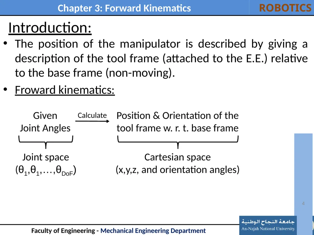
Introduction: The position of the manipulator is described by giving a description of the tool frame (attached to the E.E.) relative to the base frame (non-moving).
Froward kinematics: 4 Given
Joint Angles Joint space
(θ1,θ1,…,θDoF) Calculate Position & Orientation of the tool frame w. r. t. base frame Cartesian space
(x,y,z, and orientation angles)<br>
05
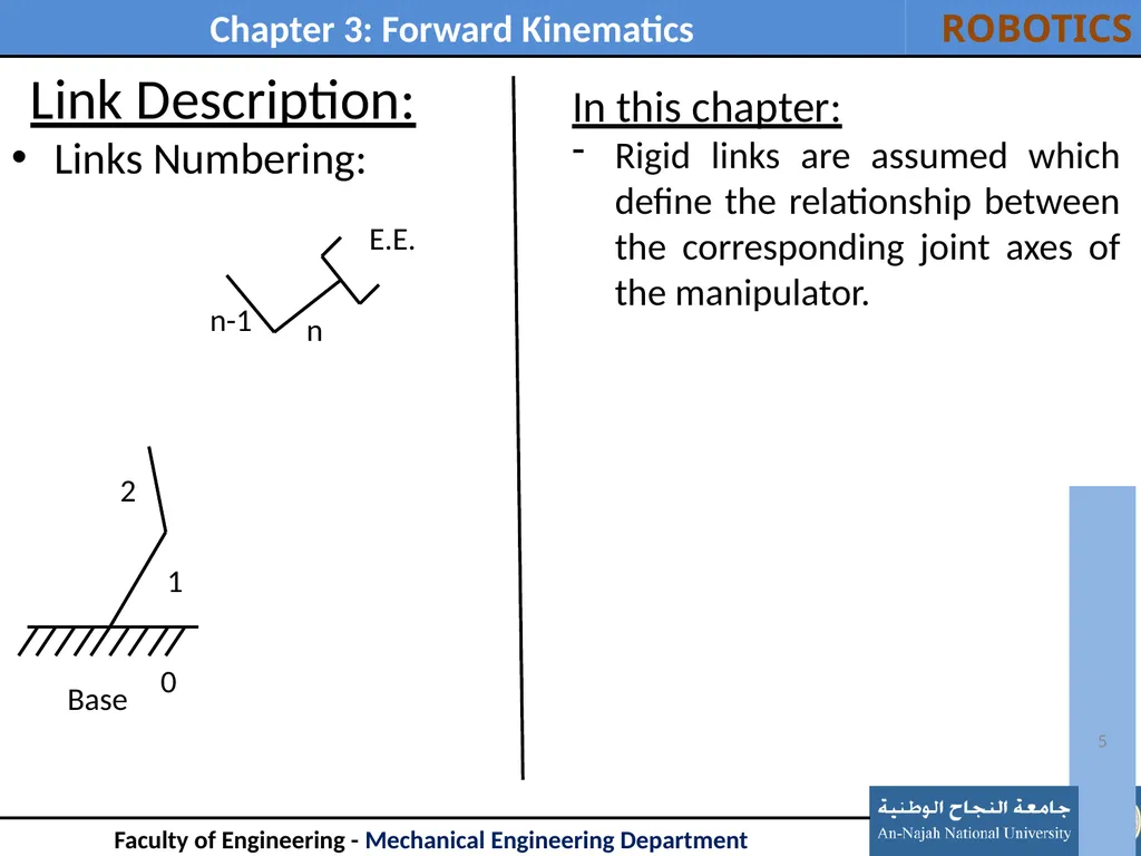
Link Description: Links Numbering: 5 In this chapter:
Rigid links are assumed which define the relationship between the corresponding joint axes of the manipulator.<br>
06
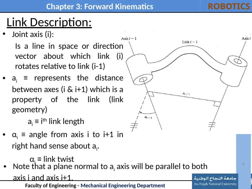
Link Description: Joint axis (i):
Is a line in space or direction vector about which link (i) rotates relative to link (i-1)
ai ≡ represents the distance between axes (i & i+1) which is a property of the link (link geometry)
ai ≡ ith link length
αi ≡ angle from axis i to i+1 in right hand sense about ai.
αi ≡ link twist 6 Note that a plane normal to ai axis will be parallel to both
axis i and axis i+1.<br>
07
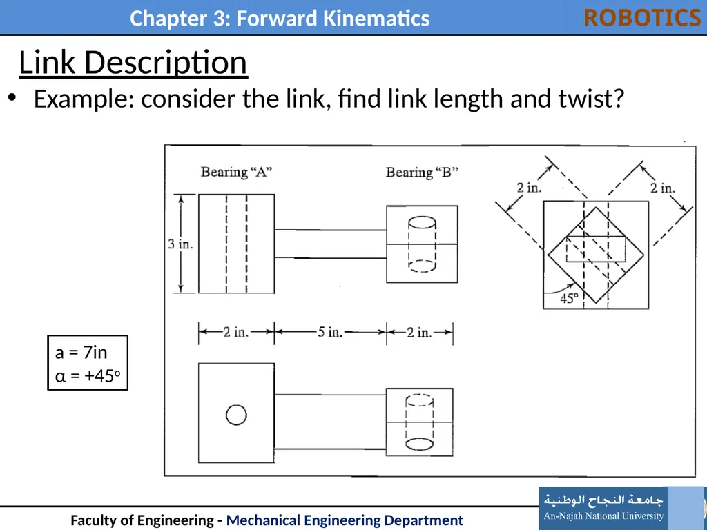
Link Description Example: consider the link, find link length and twist? 7 a = 7in
α = +45o<br>
08
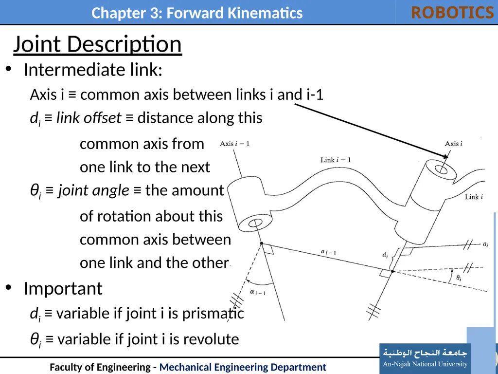
Joint Description Intermediate link:
Axis i ≡ common axis between links i and i-1
di ≡ link offset ≡ distance along this
common axis from
one link to the next
θi ≡ joint angle ≡ the amount
of rotation about this
common axis between
one link and the other
Important
di ≡ variable if joint i is prismatic
θi ≡ variable if joint i is revolute 8<br>
09
Joint Description First and last links:
Use a0 = 0 and α0 = 0. And an and αn are not needed to be defined
Joints 1:
Revolute the zero position for θ1 is chosen arbitrarily.
d1 = 0.
Prismatic the zero position for d1 is chosen arbitrarily.
θ1 = 0.
Joints n: the same convention as joint 1. 9 Zero values were assigned so that later calculations will be as
simple as possible<br>
10
Joint Description Link parameters
Hence, any robot can be described kinematically by giving the values of four quantities for each link. Two describe the link itself, and two describe the link's connection to a neighboring link. In the usual case of a revolute joint, θi is called the joint variable, and the other three quantities would be fixed link parameters. For prismatic joints, d1 is the joint variable, and the other three quantities are fixed link parameters. The definition of mechanisms by means of these quantities is a convention usually called the Denavit—Hartenberg notation 10<br>
11
Convention for attaching frames to links 11<br>
12
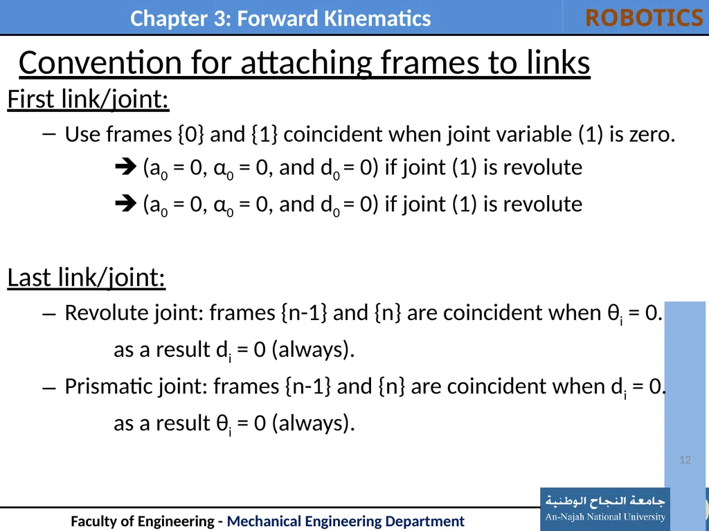
Convention for attaching frames to links First link/joint:
Use frames {0} and {1} coincident when joint variable (1) is zero.
(a0 = 0, α0 = 0, and d0 = 0) if joint (1) is revolute
(a0 = 0, α0 = 0, and d0 = 0) if joint (1) is revolute
Last link/joint:
Revolute joint: frames {n-1} and {n} are coincident when θi = 0.
as a result di = 0 (always).
Prismatic joint: frames {n-1} and {n} are coincident when di = 0.
as a result θi = 0 (always). 12<br>
13
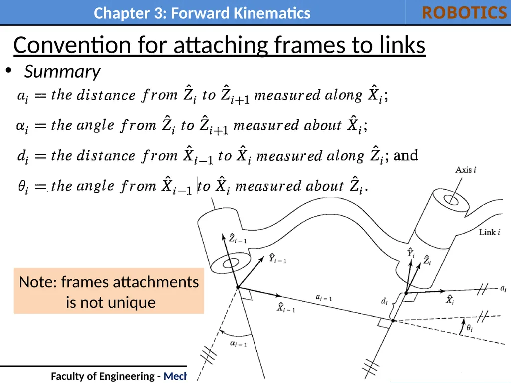
Convention for attaching frames to links Summary 13 Note: frames attachments
is not unique<br>
14
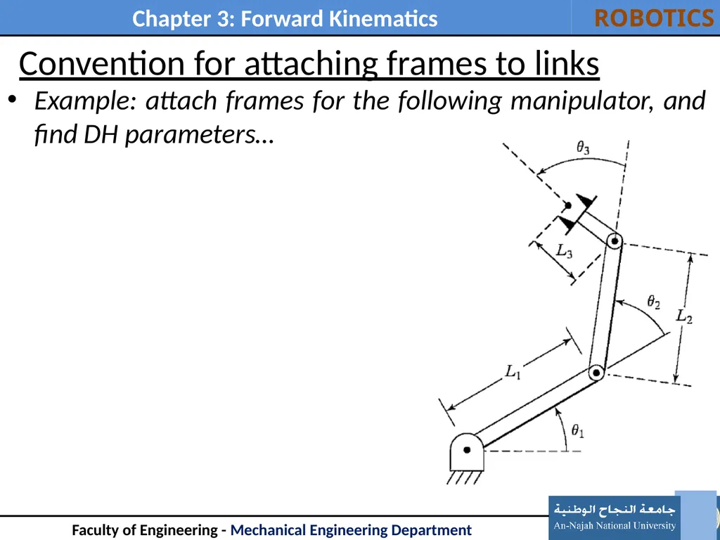
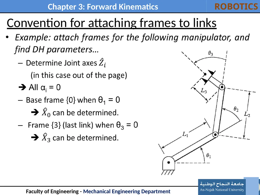
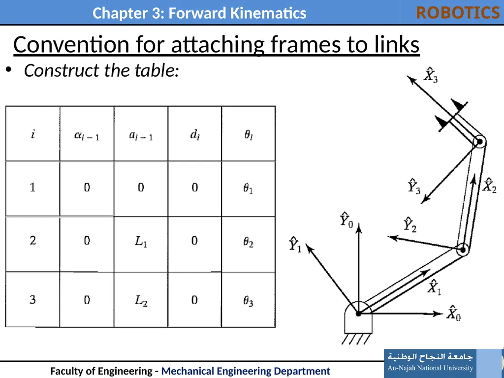
Convention for attaching frames to links Example: attach frames for the following manipulator, and find DH parameters… 14<br>
15
Convention for attaching frames to links 15<br>
16
Convention for attaching frames to links Construct the table: 16<br>
17
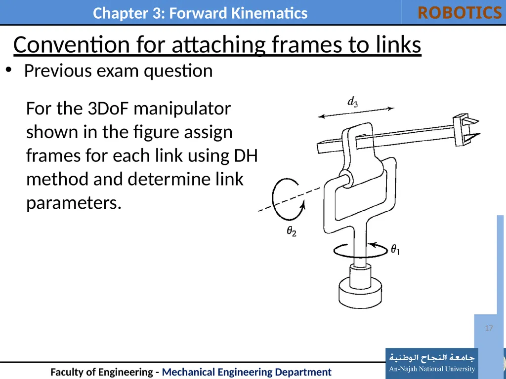
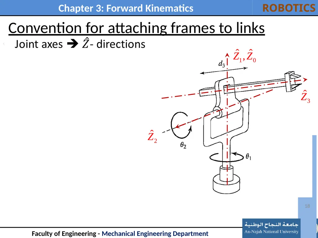
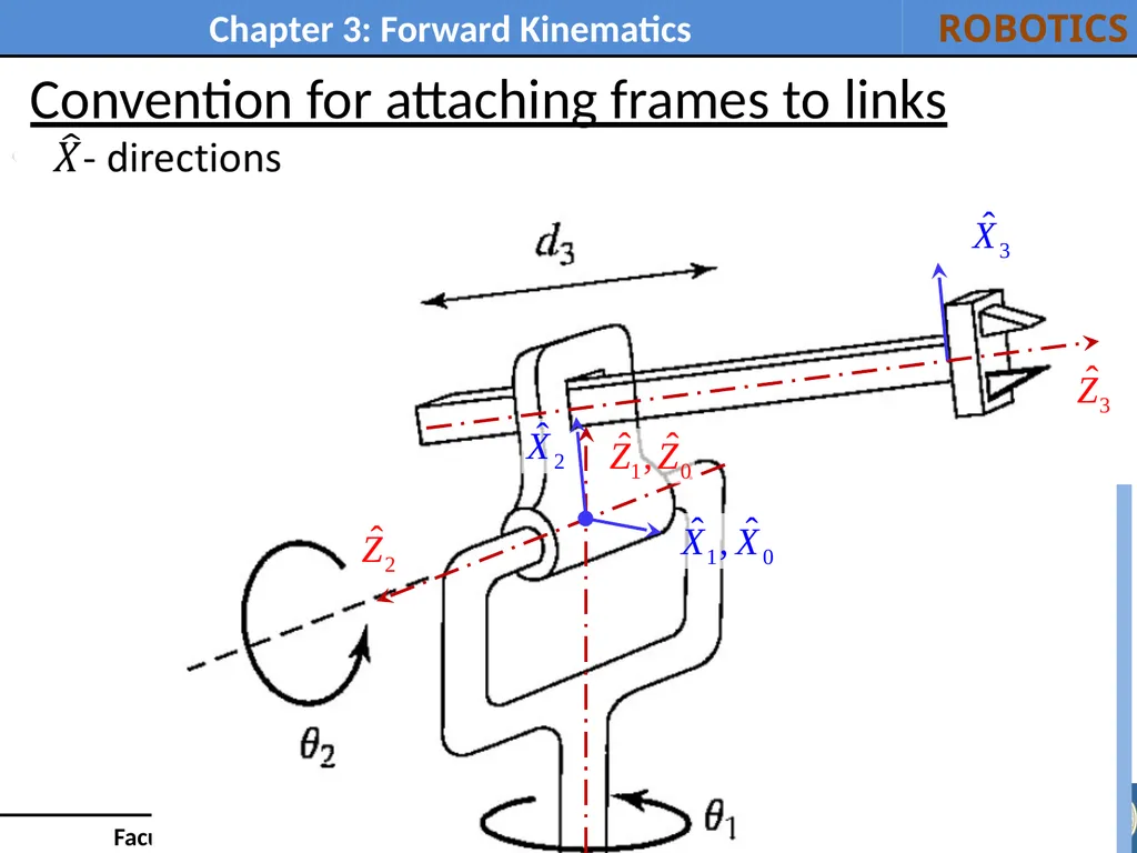
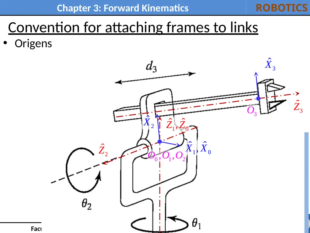
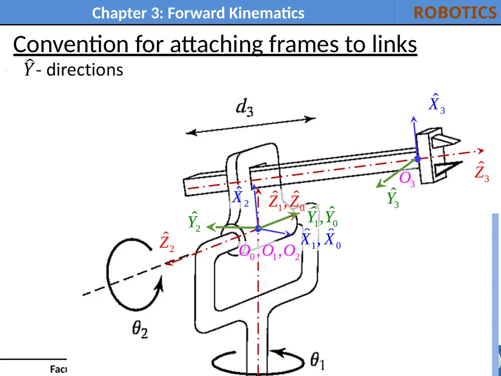
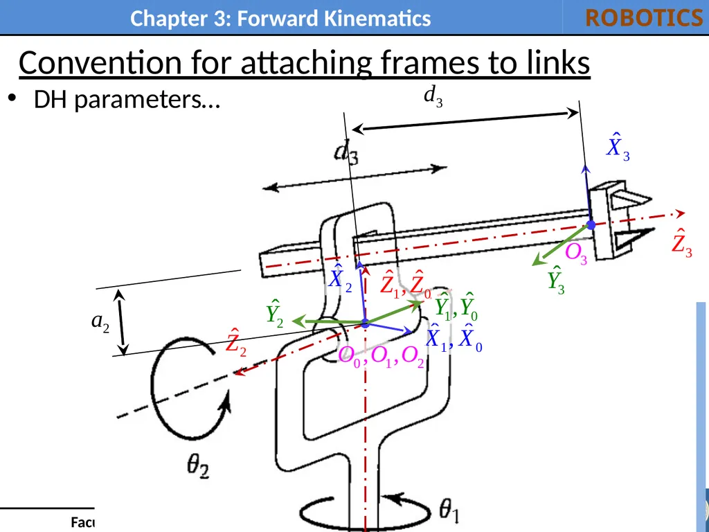
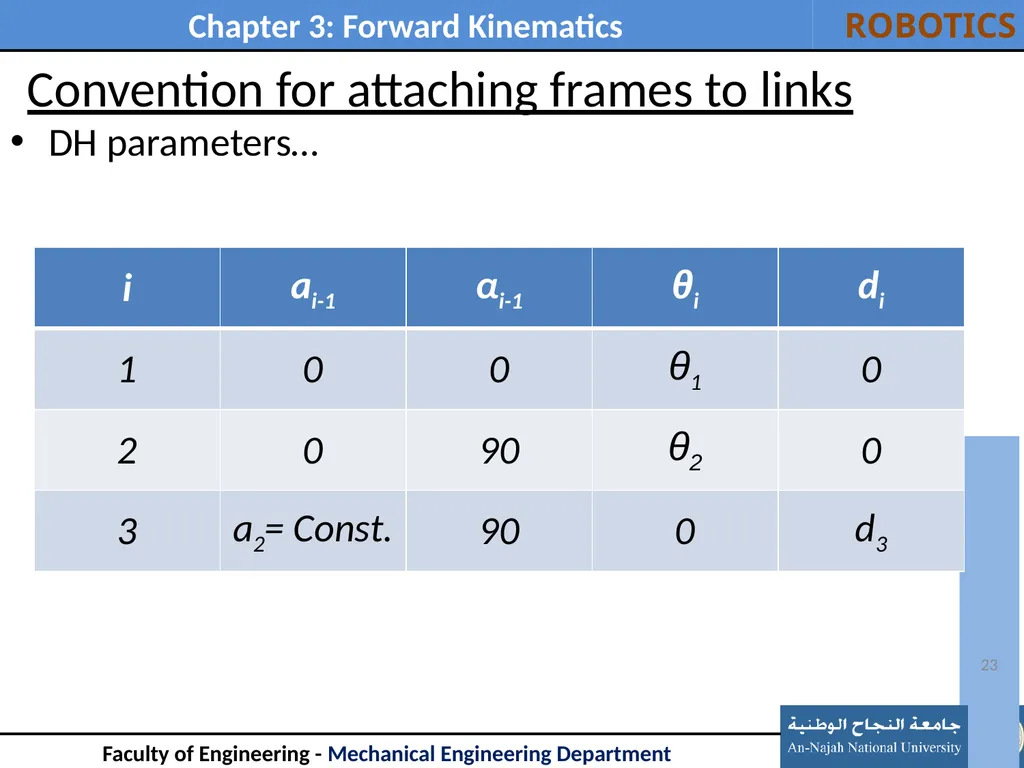
Convention for attaching frames to links Previous exam question 17 For the 3DoF manipulator shown in the figure assign frames for each link using DH method and determine link parameters.<br>
18
Convention for attaching frames to links 18<br>
19
Convention for attaching frames to links 19<br>
20
Convention for attaching frames to links Origens 20<br>
21
Convention for attaching frames to links 21<br>
22
Convention for attaching frames to links DH parameters… 22<br>
23
Convention for attaching frames to links DH parameters… 23<br>
24
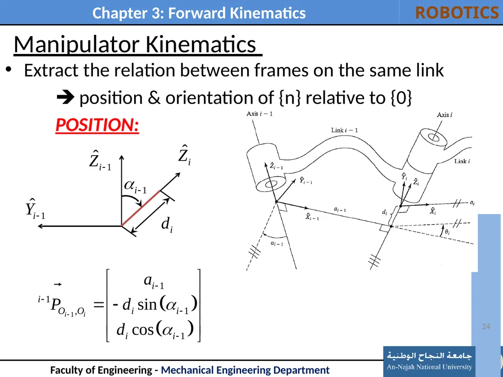
Manipulator Kinematics Extract the relation between frames on the same link
position & orientation of {n} relative to {0}
POSITION: 24<br>
25
Manipulator Kinematics 25<br>
26
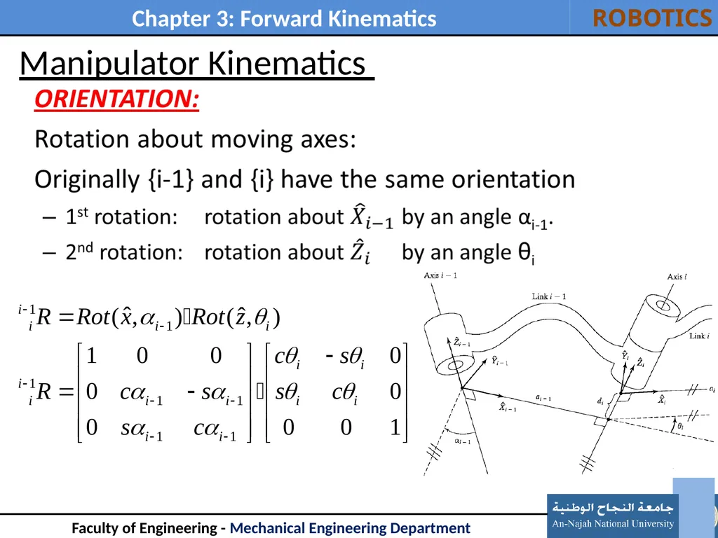
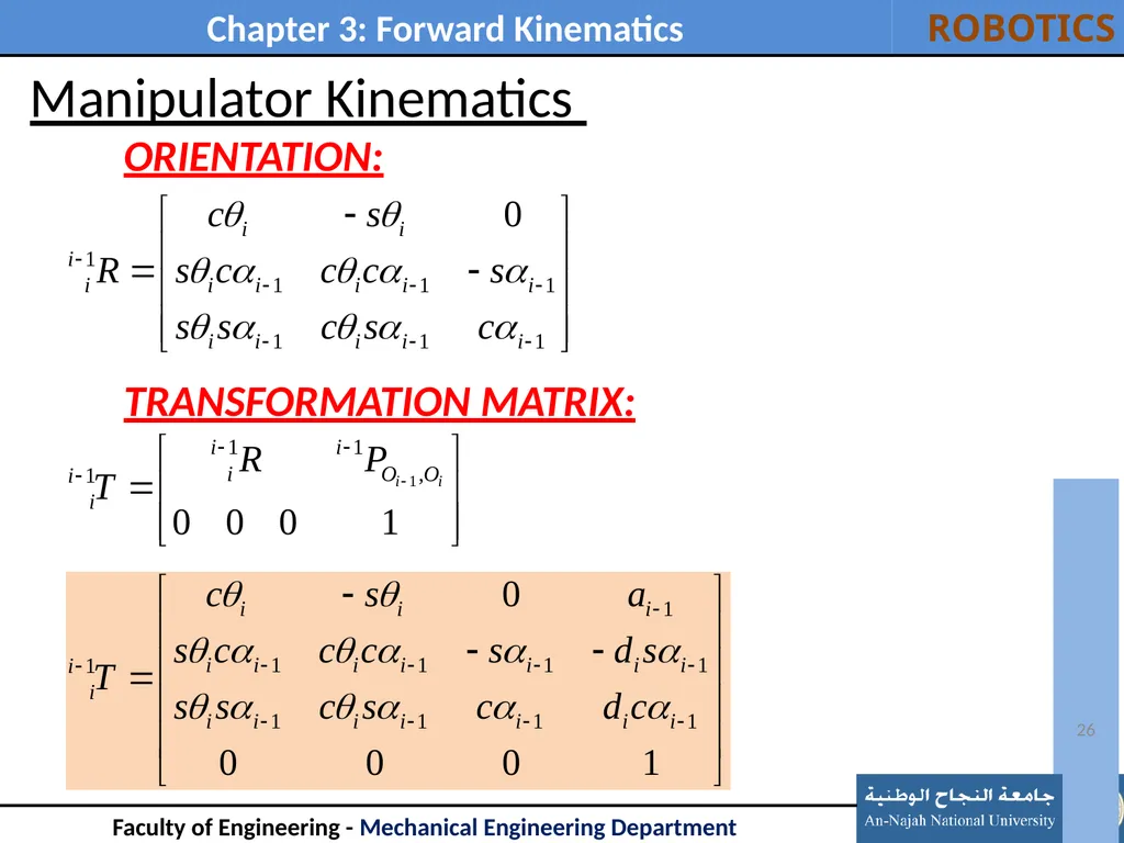
Manipulator Kinematics ORIENTATION:
TRANSFORMATION MATRIX: 26<br>
27
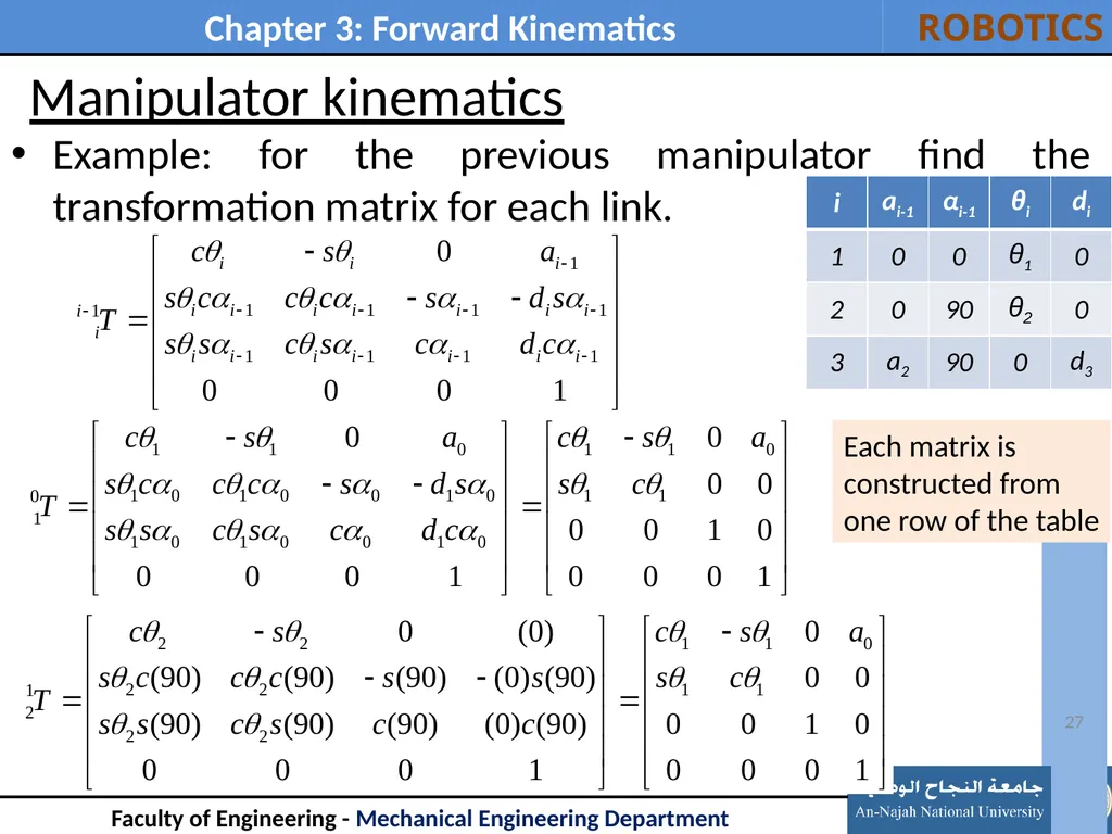
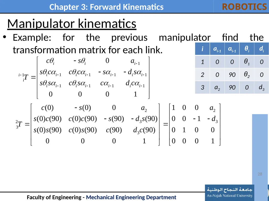
Manipulator kinematics Example: for the previous manipulator find the transformation matrix for each link. 27 Each matrix is
constructed from
one row of the table<br>
28
Manipulator kinematics Example: for the previous manipulator find the transformation matrix for each link. 28<br>
29
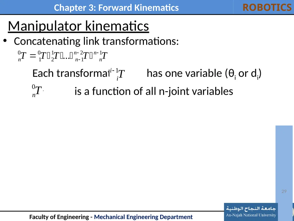
Manipulator kinematics Concatenating link transformations:
Each transformation has one variable (θi or di)
is a function of all n-joint variables 29<br>
30
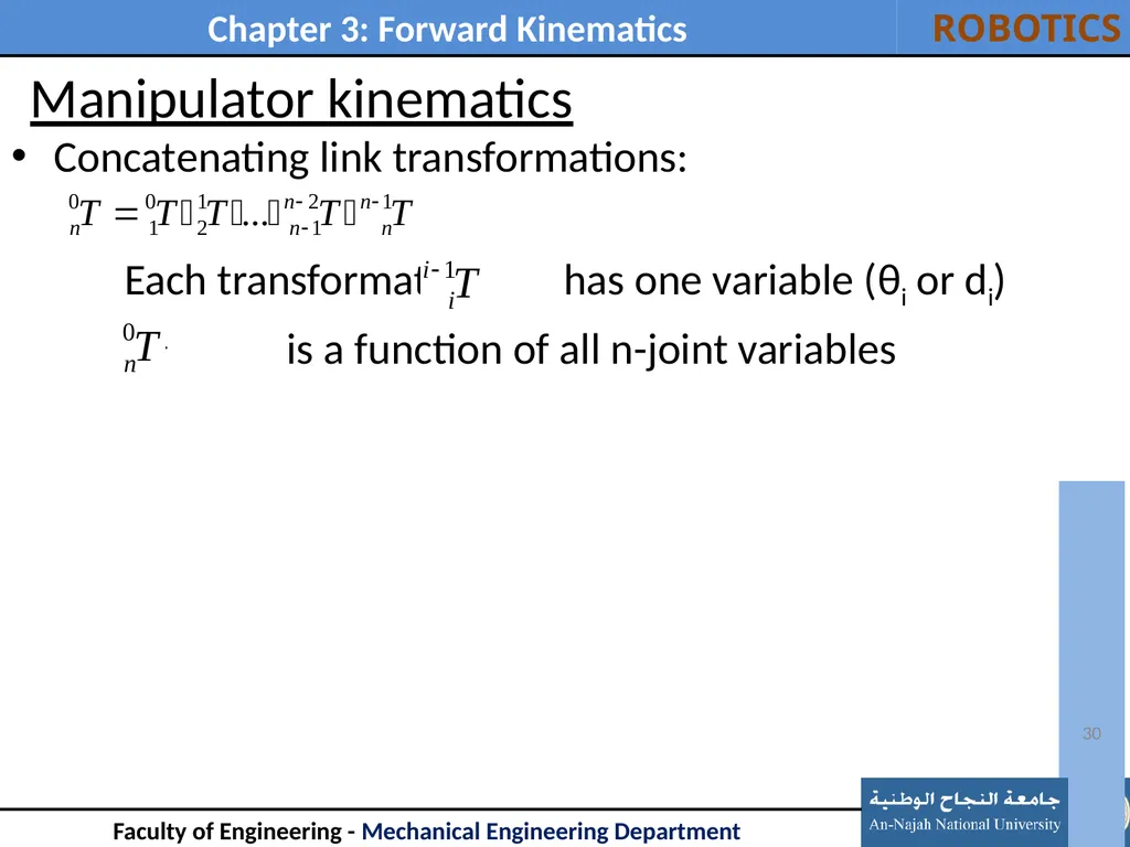
Manipulator kinematics Concatenating link transformations:
Each transformation has one variable (θi or di)
is a function of all n-joint variables 30<br>
31
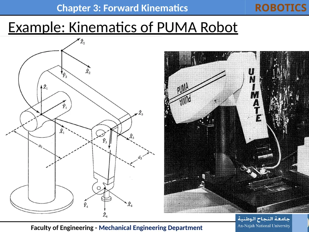
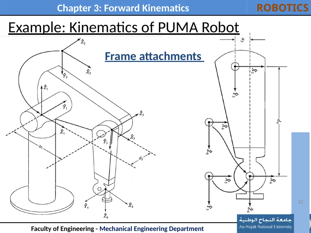
Example: Kinematics of PUMA Robot 31<br>
32
32 Example: Kinematics of PUMA Robot Frame attachments<br>
33
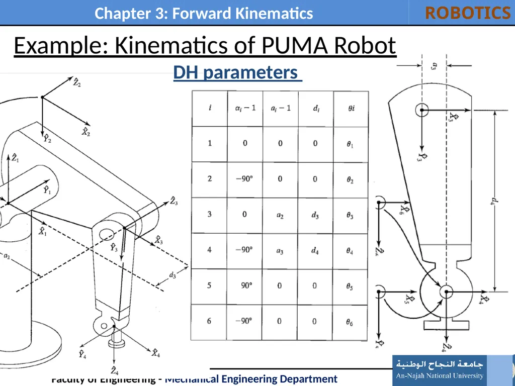
33 Example: Kinematics of PUMA Robot DH parameters<br>
34
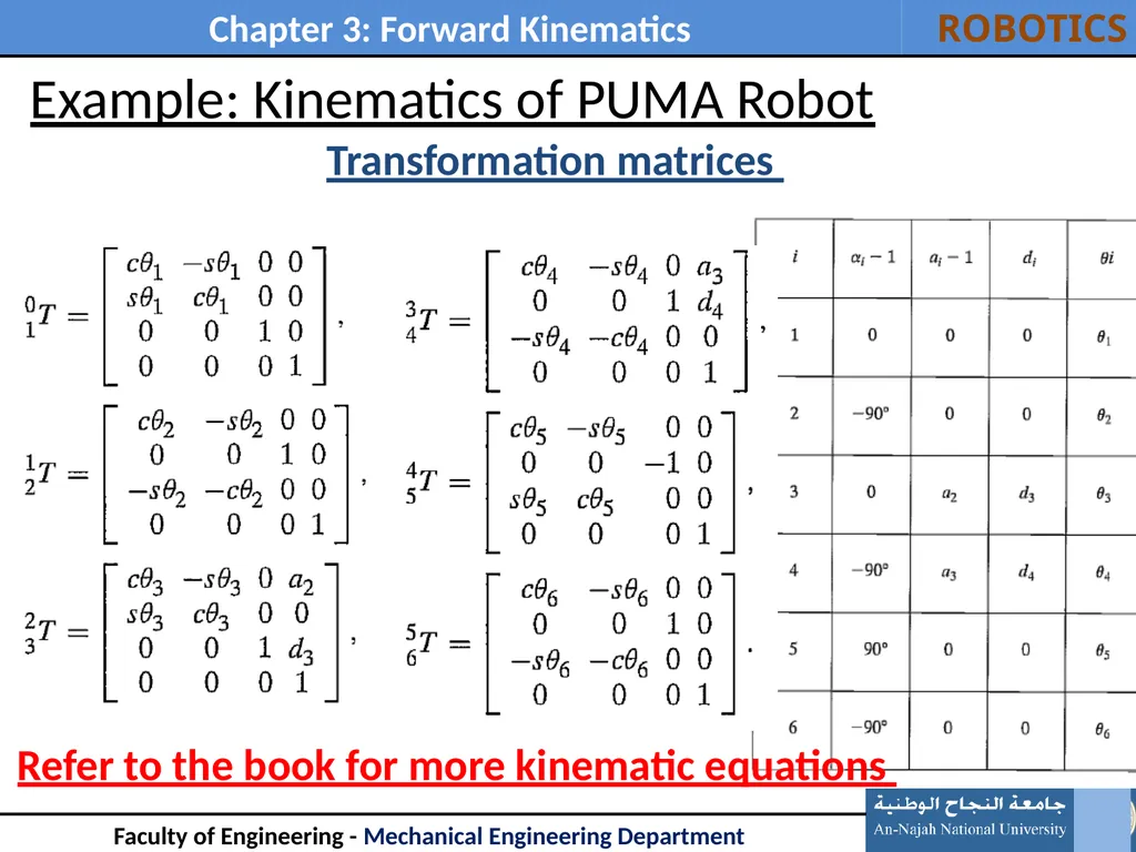
34 Example: Kinematics of PUMA Robot Transformation matrices Refer to the book for more kinematic equations<br>
35
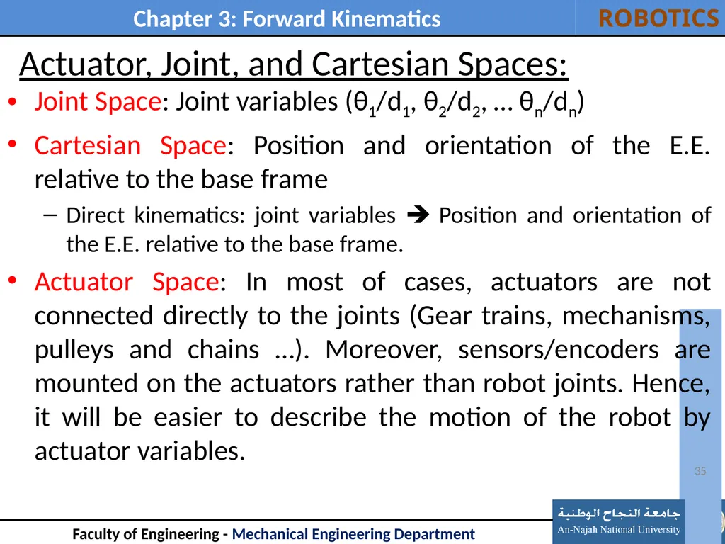
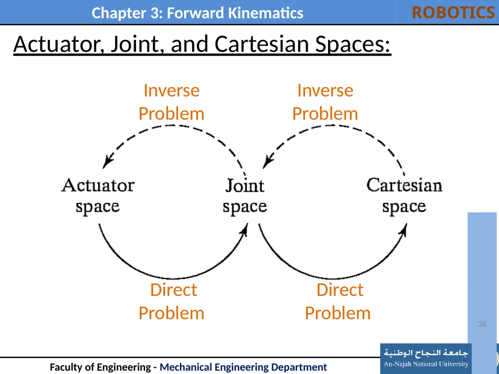
Joint Space: Joint variables (θ1/d1, θ2/d2, … θn/dn)
Cartesian Space: Position and orientation of the E.E. relative to the base frame
Direct kinematics: joint variables Position and orientation of the E.E. relative to the base frame.
Actuator Space: In most of cases, actuators are not connected directly to the joints (Gear trains, mechanisms, pulleys and chains …). Moreover, sensors/encoders are mounted on the actuators rather than robot joints. Hence, it will be easier to describe the motion of the robot by actuator variables. 35 Actuator, Joint, and Cartesian Spaces:<br>
36
36 Actuator, Joint, and Cartesian Spaces: Inverse
Problem Inverse
Problem Direct
Problem Direct
Problem<br>
37
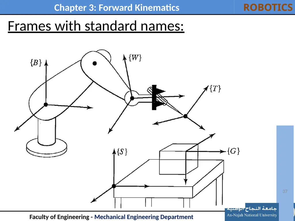
37 Frames with standard names:<br>