
PCIe Hot-Plug and Error Handling for NVMe 2019
PT
Published · 25 slides · 0 views

1 / 1


Description
PCIe Hot-Plug and Error Handling for NVMe 2019 NVMe Annual Members Meeting and Developer Day March 19, 2019 Prepared by: Austin Bolen, Server Storage Technologist, Dell EMC Curtis Ballard, Storage Technologist, HPE Joe Cowan, Senior
Related Topics
Share
Embed code
Download this presentation From Below
"PCIe Hot-Plug and Error Handling for NVMe 2019" is the property of its rightful owner. Permission is granted to download and print the materials on this website for personal, non-commercial use only, and to display it on your personal computer provided you do not modify the materials and that you retain all copyright notices contained in the materials. By downloading content from our website, you accept the terms of this agreement.
Presentation Transcript
01
PCIe Hot-Plug and Error Handling for NVMe
2019 NVMe™ Annual Members Meeting and Developer Day
March 19, 2019
Prepared by:
Austin Bolen, Server Storage Technologist, Dell EMC
Curtis Ballard, Storage Technologist, HPE
Joe Cowan, Senior Systems Architect, HPE<br>
02
Agenda The Importance of Hot-Plug and Error Handling for NVMe™
Challenges with NVMe Hot-Plug and Error Handling
Solutions to NVMe Hot-Plug and Error Handling Challenges
Questions<br>
Challenges with NVMe Hot-Plug and Error Handling
Solutions to NVMe Hot-Plug and Error Handling Challenges
Questions<br>
03
The Importance of Hot-Plug and
Error Handling for NVMe™<br>
04
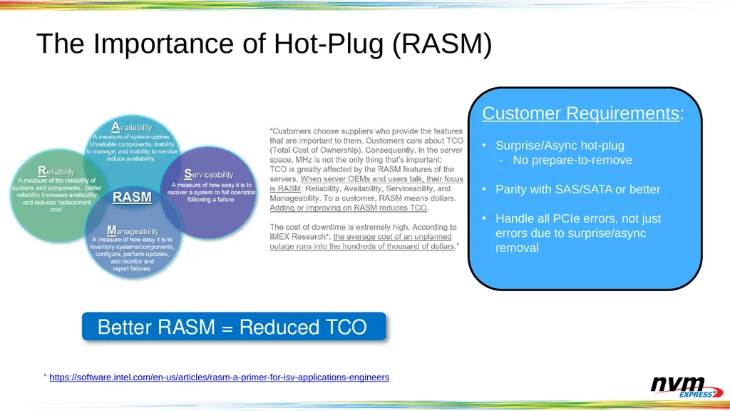
The Importance of Hot-Plug (RASM) * https://software.intel.com/en-us/articles/rasm-a-primer-for-isv-applications-engineers Better RASM = Reduced TCO Customer Requirements:
Surprise/Async hot-plug
- No prepare-to-remove
Parity with SAS/SATA or better
Handle all PCIe errors, not just errors due to surprise/async removal<br>
Surprise/Async hot-plug
- No prepare-to-remove
Parity with SAS/SATA or better
Handle all PCIe errors, not just errors due to surprise/async removal<br>
05
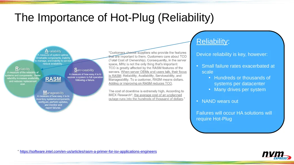
The Importance of Hot-Plug (Reliability) * https://software.intel.com/en-us/articles/rasm-a-primer-for-isv-applications-engineers Reliability:
Device reliability is key, however:
Small failure rates exacerbated at scale
Hundreds or thousands of systems per datacenter
Many drives per system
NAND wears out
Failures will occur HA solutions will require Hot-Plug<br>
Device reliability is key, however:
Small failure rates exacerbated at scale
Hundreds or thousands of systems per datacenter
Many drives per system
NAND wears out
Failures will occur HA solutions will require Hot-Plug<br>
06
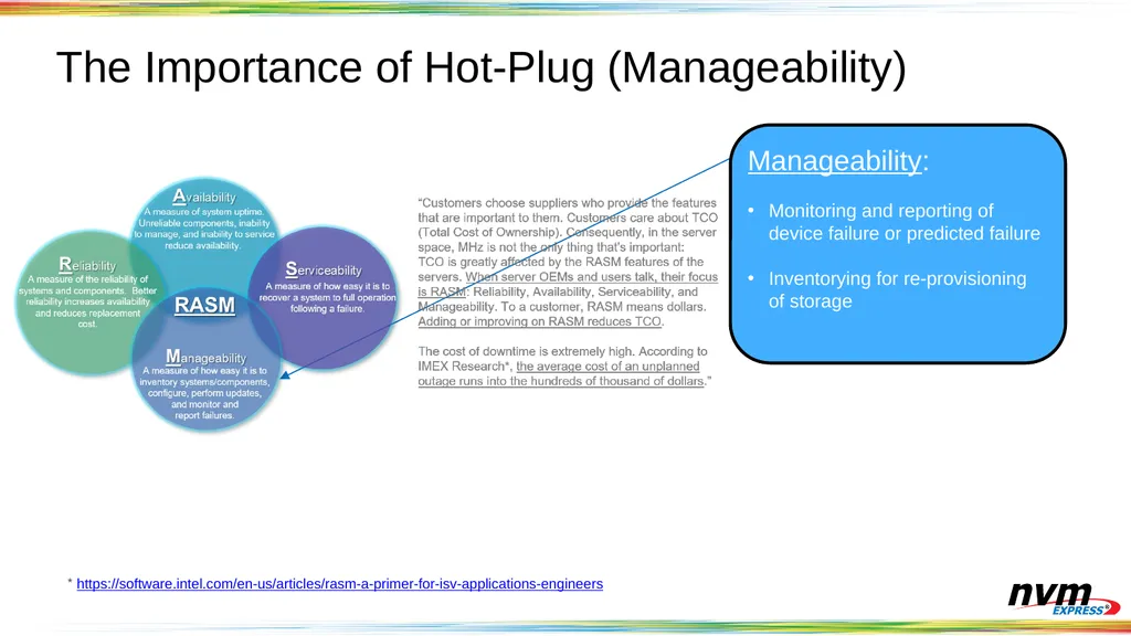
The Importance of Hot-Plug (Manageability) * https://software.intel.com/en-us/articles/rasm-a-primer-for-isv-applications-engineers Manageability:
Monitoring and reporting of device failure or predicted failure
Inventorying for re-provisioning of storage<br>
Monitoring and reporting of device failure or predicted failure
Inventorying for re-provisioning of storage<br>
07
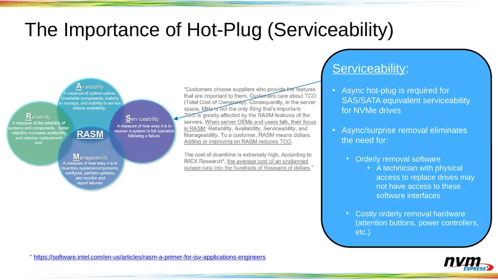
The Importance of Hot-Plug (Serviceability) * https://software.intel.com/en-us/articles/rasm-a-primer-for-isv-applications-engineers Serviceability:
Async hot-plug is required for SAS/SATA equivalent serviceability for NVMe drives
Async/surprise removal eliminates the need for:
Orderly removal software
A technician with physical access to replace drives may not have access to these software interfaces
Costly orderly removal hardware (attention buttons, power controllers, etc.)<br>
Async hot-plug is required for SAS/SATA equivalent serviceability for NVMe drives
Async/surprise removal eliminates the need for:
Orderly removal software
A technician with physical access to replace drives may not have access to these software interfaces
Costly orderly removal hardware (attention buttons, power controllers, etc.)<br>
08
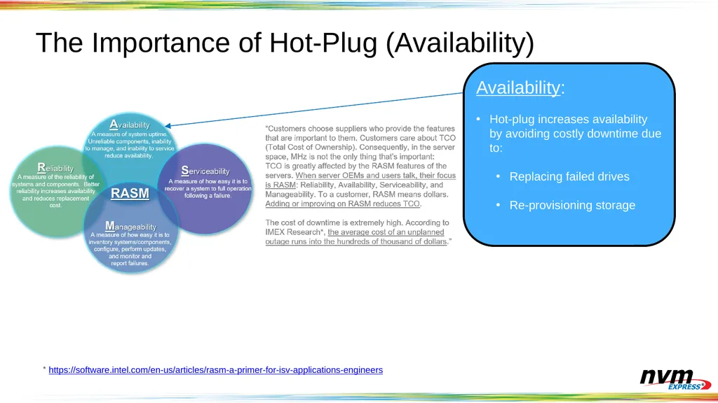
The Importance of Hot-Plug (Availability) * https://software.intel.com/en-us/articles/rasm-a-primer-for-isv-applications-engineers Availability:
Hot-plug increases availability by avoiding costly downtime due to:
Replacing failed drives
Re-provisioning storage<br>
Hot-plug increases availability by avoiding costly downtime due to:
Replacing failed drives
Re-provisioning storage<br>
09
Challenges with NVMe™ Hot-Plug and
Error Handling<br>
10
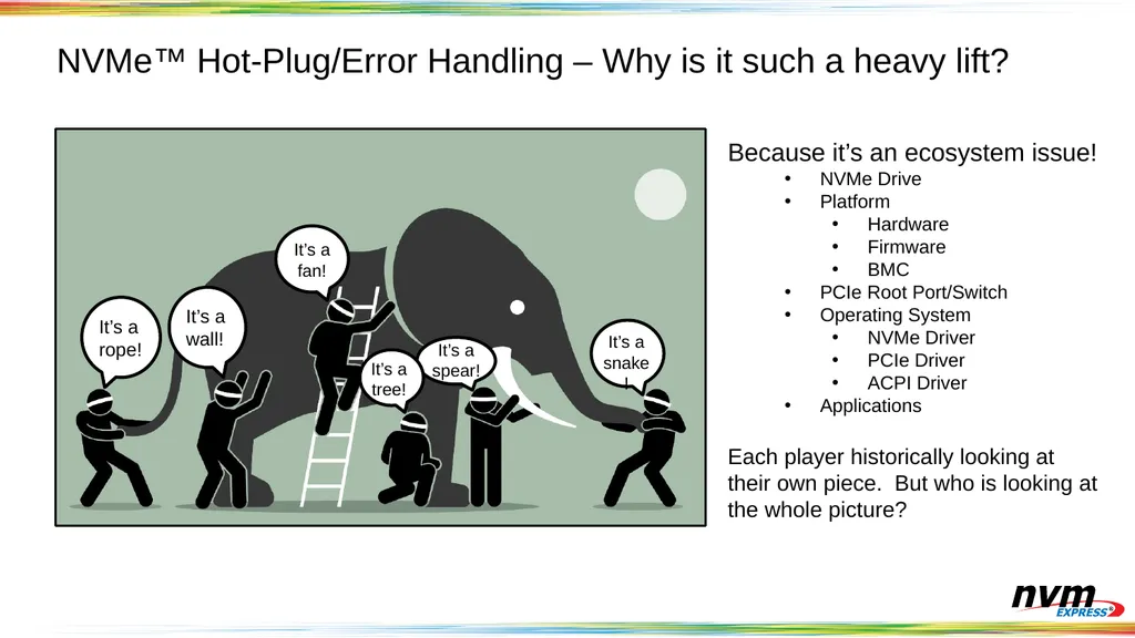
NVMe™ Hot-Plug/Error Handling – Why is it such a heavy lift? Because it’s an ecosystem issue!
NVMe Drive
Platform
Hardware
Firmware
BMC
PCIe Root Port/Switch
Operating System
NVMe Driver
PCIe Driver
ACPI Driver
Applications
Each player historically looking at their own piece. But who is looking at the whole picture?<br>
NVMe Drive
Platform
Hardware
Firmware
BMC
PCIe Root Port/Switch
Operating System
NVMe Driver
PCIe Driver
ACPI Driver
Applications
Each player historically looking at their own piece. But who is looking at the whole picture?<br>
11
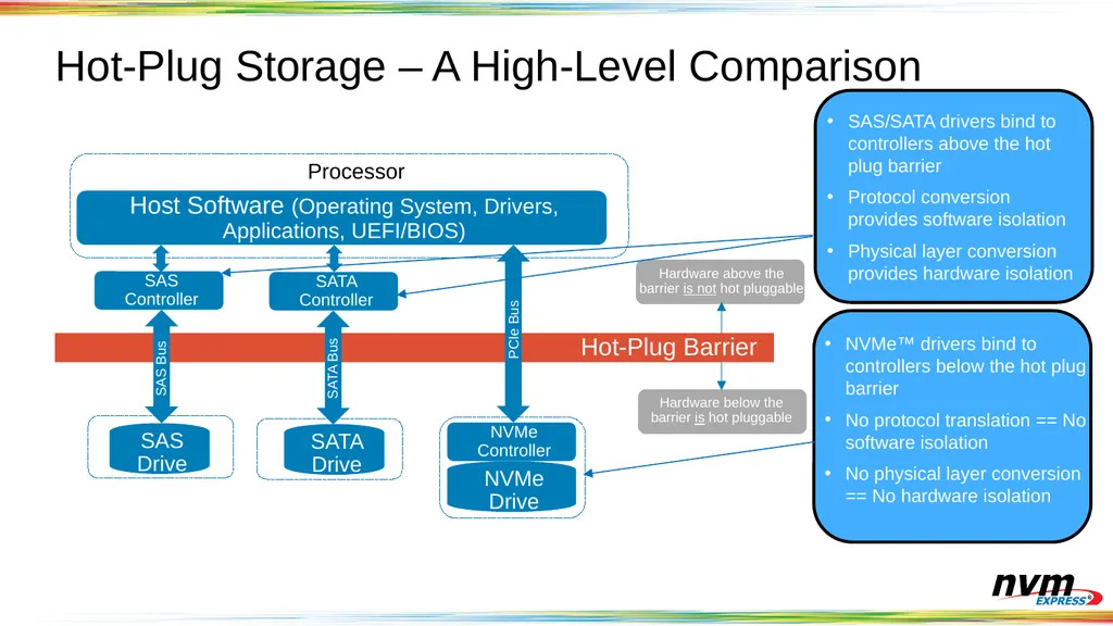
Hot-Plug Storage – A High-Level Comparison Host Software (Operating System, Drivers, Applications, UEFI/BIOS) SAS Controller SATA Controller NVMe Controller SAS Drive SATA Drive NVMe Drive Hot-Plug Barrier Processor Hardware above the barrier is not hot pluggable Hardware below the barrier is hot pluggable SAS Bus SATA Bus PCIe Bus SAS/SATA drivers bind to controllers above the hot plug barrier
Protocol conversion provides software isolation
Physical layer conversion provides hardware isolation NVMe™ drivers bind to controllers below the hot plug barrier
No protocol translation == No software isolation
No physical layer conversion == No hardware isolation<br>
Protocol conversion provides software isolation
Physical layer conversion provides hardware isolation NVMe™ drivers bind to controllers below the hot plug barrier
No protocol translation == No software isolation
No physical layer conversion == No hardware isolation<br>
12
The PCIe Hot-Plug Eras
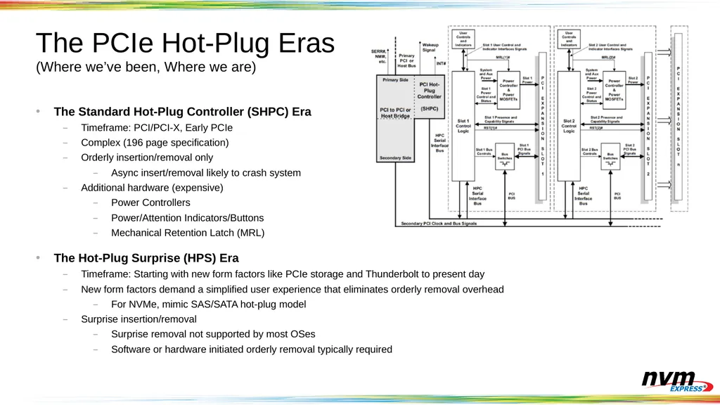
(Where we’ve been, Where we are) The Standard Hot-Plug Controller (SHPC) Era
Timeframe: PCI/PCI-X, Early PCIe
Complex (196 page specification)
Orderly insertion/removal only
Async insert/removal likely to crash system
Additional hardware (expensive)
Power Controllers
Power/Attention Indicators/Buttons
Mechanical Retention Latch (MRL)
The Hot-Plug Surprise (HPS) Era
Timeframe: Starting with new form factors like PCIe storage and Thunderbolt to present day
New form factors demand a simplified user experience that eliminates orderly removal overhead
For NVMe, mimic SAS/SATA hot-plug model
Surprise insertion/removal
Surprise removal not supported by most OSes
Software or hardware initiated orderly removal typically required<br>
Timeframe: PCI/PCI-X, Early PCIe
Complex (196 page specification)
Orderly insertion/removal only
Async insert/removal likely to crash system
Additional hardware (expensive)
Power Controllers
Power/Attention Indicators/Buttons
Mechanical Retention Latch (MRL)
The Hot-Plug Surprise (HPS) Era
Timeframe: Starting with new form factors like PCIe storage and Thunderbolt to present day
New form factors demand a simplified user experience that eliminates orderly removal overhead
For NVMe, mimic SAS/SATA hot-plug model
Surprise insertion/removal
Surprise removal not supported by most OSes
Software or hardware initiated orderly removal typically required<br>
13
Hot-Plug Issues Persist After SHPC and HPS System crashes are still possible
Errors if orderly removal process not followed with SHPC
Synthesized all 1’s data during errors - not always handled correctly by software
No strict model for interaction of stack components - leads to race conditions causing crashes and deadlocks
Other issues
Timely detection of removal and insertion (detection while in low power state)
Mechanical insert/remove issues (slow insert, angled insert, etc.)
Issues often require changes outside the component under test (OS, switch, etc.)
SHPC and HPS aren’t robust enough for complex use cases<br>
Errors if orderly removal process not followed with SHPC
Synthesized all 1’s data during errors - not always handled correctly by software
No strict model for interaction of stack components - leads to race conditions causing crashes and deadlocks
Other issues
Timely detection of removal and insertion (detection while in low power state)
Mechanical insert/remove issues (slow insert, angled insert, etc.)
Issues often require changes outside the component under test (OS, switch, etc.)
SHPC and HPS aren’t robust enough for complex use cases<br>
14
Solutions to NVMe™ Hot-Plug and
Error Handling Challenges<br>
15
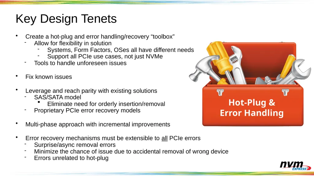
Key Design Tenets Create a hot-plug and error handling/recovery “toolbox”
Allow for flexibility in solution
Systems, Form Factors, OSes all have different needs
Support all PCIe use cases, not just NVMe
Tools to handle unforeseen issues
Fix known issues
Leverage and reach parity with existing solutions
SAS/SATA model
Eliminate need for orderly insertion/removal
Proprietary PCIe error recovery models
Multi-phase approach with incremental improvements
Error recovery mechanisms must be extensible to all PCIe errors
Surprise/async removal errors
Minimize the chance of issue due to accidental removal of wrong device
Errors unrelated to hot-plug Hot-Plug
&
Error Handling<br>
Allow for flexibility in solution
Systems, Form Factors, OSes all have different needs
Support all PCIe use cases, not just NVMe
Tools to handle unforeseen issues
Fix known issues
Leverage and reach parity with existing solutions
SAS/SATA model
Eliminate need for orderly insertion/removal
Proprietary PCIe error recovery models
Multi-phase approach with incremental improvements
Error recovery mechanisms must be extensible to all PCIe errors
Surprise/async removal errors
Minimize the chance of issue due to accidental removal of wrong device
Errors unrelated to hot-plug Hot-Plug
&
Error Handling<br>
16
Key Design Tenets Hooks for time-to-market
System hardware/firmware changes should be sufficient for:
New system designs and form factors
Fixing defects/unforeseen issues
Avoid/minimize need for:
Future OS changes
Future PCIe Root Port/Switch changes<br>
System hardware/firmware changes should be sufficient for:
New system designs and form factors
Fixing defects/unforeseen issues
Avoid/minimize need for:
Future OS changes
Future PCIe Root Port/Switch changes<br>
17
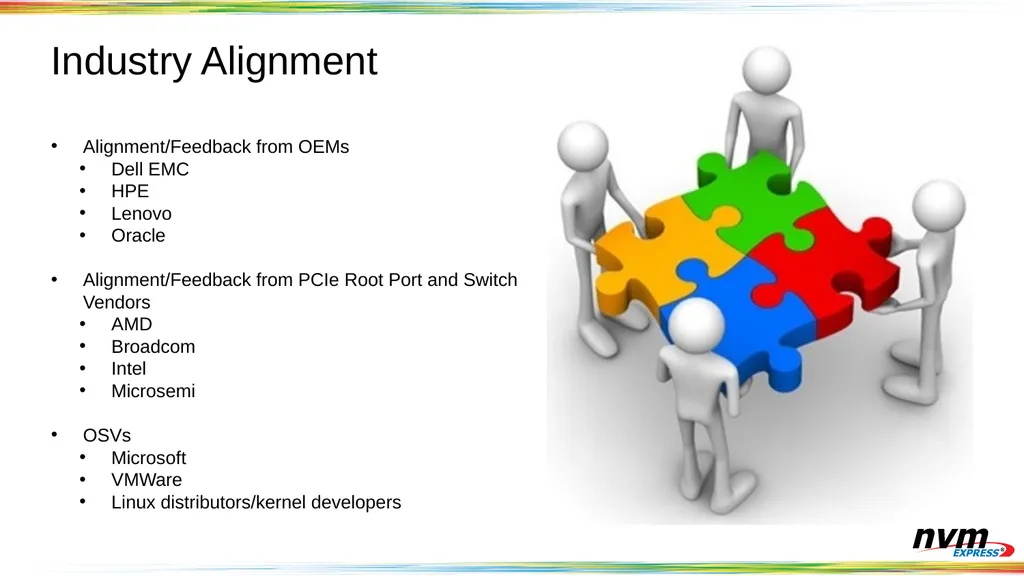
Industry Alignment Alignment/Feedback from OEMs
Dell EMC
HPE
Lenovo
Oracle
Alignment/Feedback from PCIe Root Port and Switch Vendors
AMD
Broadcom
Intel
Microsemi
OSVs
Microsoft
VMWare
Linux distributors/kernel developers<br>
Dell EMC
HPE
Lenovo
Oracle
Alignment/Feedback from PCIe Root Port and Switch Vendors
AMD
Broadcom
Intel
Microsemi
OSVs
Microsoft
VMWare
Linux distributors/kernel developers<br>
18
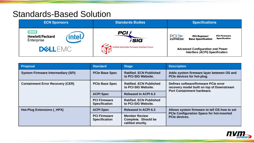
Standards-Based Solution<br>
19
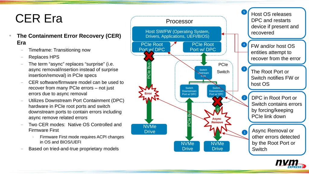
CER Era Host SW/FW (Operating System, Drivers, Applications, UEFI/BIOS) PCIe Root Port w/ DPC NVMe Drive Processor PCIe Bus Error PCIe Root Port w/ DPC Switch Upstream Port Switch Downstream Port w/ DPC Switch Downstream Port w/ DPC NVMe Drive NVMe Drive Async Removal or other errors detected by the Root Port or Switch DPC in Root Port or Switch contains errors by forcing/keeping PCIe link down The Root Port or Switch notifies FW or host OS FW and/or host OS entities attempt to recover from the error PCIe Bus PCIe Bus Async Remove Host OS releases DPC and restarts device if present and recovered PCIe
Switch The Containment Error Recovery (CER) Era
Timeframe: Transitioning now
Replaces HPS
The term “async” replaces “surprise” (i.e. async removal/insertion instead of surprise insertion/removal) in PCIe specs
CER software/firmware model can be used to recover from many PCIe errors – not just errors due to async removal
Utilizes Downstream Port Containment (DPC) hardware in PCIe root ports and switch downstream ports to contain errors including async remove related errors
Two CER modes: Native OS Controlled and Firmware First
Firmware First mode requires ACPI changes in OS and BIOS/UEFI
Based on tried-and-true proprietary models<br>
Switch The Containment Error Recovery (CER) Era
Timeframe: Transitioning now
Replaces HPS
The term “async” replaces “surprise” (i.e. async removal/insertion instead of surprise insertion/removal) in PCIe specs
CER software/firmware model can be used to recover from many PCIe errors – not just errors due to async removal
Utilizes Downstream Port Containment (DPC) hardware in PCIe root ports and switch downstream ports to contain errors including async remove related errors
Two CER modes: Native OS Controlled and Firmware First
Firmware First mode requires ACPI changes in OS and BIOS/UEFI
Based on tried-and-true proprietary models<br>
20
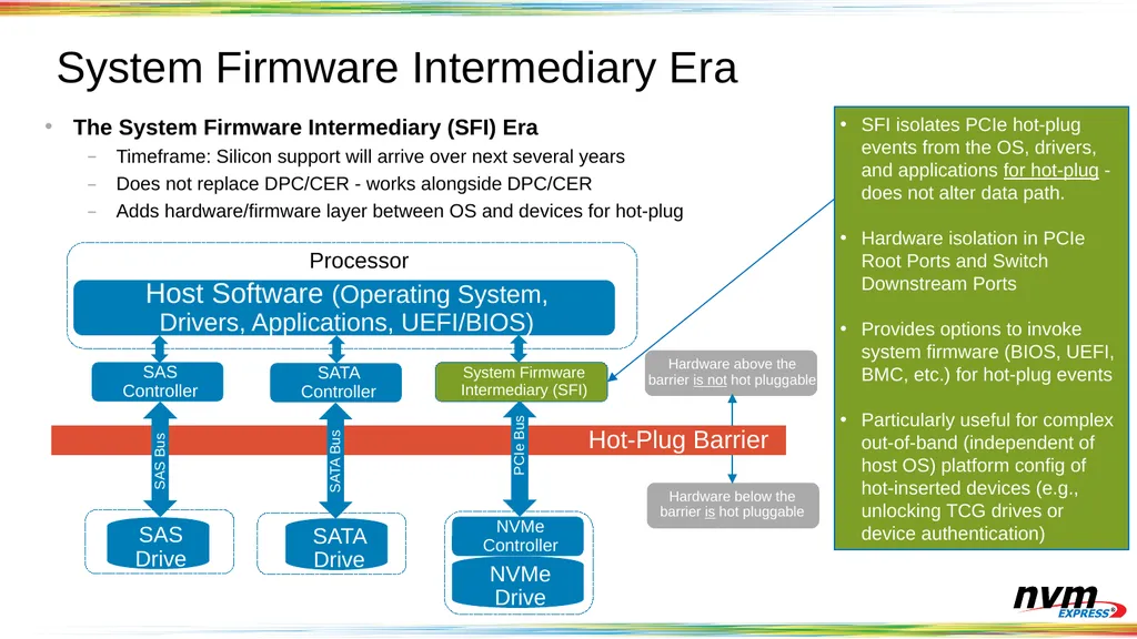
System Firmware Intermediary Era Host Software (Operating System, Drivers, Applications, UEFI/BIOS) SAS Controller SATA Controller NVMe Controller SAS Drive SATA Drive NVMe Drive Hot-Plug Barrier Processor Hardware above the barrier is not hot pluggable Hardware below the barrier is hot pluggable SAS Bus SATA Bus PCIe Bus System Firmware Intermediary (SFI) SFI isolates PCIe hot-plug events from the OS, drivers, and applications for hot-plug - does not alter data path.
Hardware isolation in PCIe Root Ports and Switch Downstream Ports
Provides options to invoke system firmware (BIOS, UEFI, BMC, etc.) for hot-plug events
Particularly useful for complex out-of-band (independent of host OS) platform config of hot-inserted devices (e.g., unlocking TCG drives or device authentication) The System Firmware Intermediary (SFI) Era
Timeframe: Silicon support will arrive over next several years
Does not replace DPC/CER - works alongside DPC/CER
Adds hardware/firmware layer between OS and devices for hot-plug<br>
Hardware isolation in PCIe Root Ports and Switch Downstream Ports
Provides options to invoke system firmware (BIOS, UEFI, BMC, etc.) for hot-plug events
Particularly useful for complex out-of-band (independent of host OS) platform config of hot-inserted devices (e.g., unlocking TCG drives or device authentication) The System Firmware Intermediary (SFI) Era
Timeframe: Silicon support will arrive over next several years
Does not replace DPC/CER - works alongside DPC/CER
Adds hardware/firmware layer between OS and devices for hot-plug<br>
21
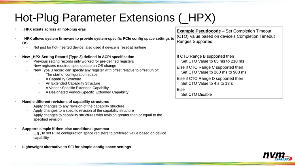
Hot-Plug Parameter Extensions (_HPX) _HPX exists across all hot-plug eras
_HPX allows system firmware to provide system-specific PCIe config space settings to OS
Not just for hot-inserted device; also used if device is reset at runtime
New _HPX Setting Record (Type 3) defined in ACPI specification
Previous setting records only worked for pre-defined registers
New registers required spec update an OS change
New Type 3 record can specify any register with offset relative to offset 0h of:
The start of configuration space
A Capability Structure
An Extended Capability Structure
A Vendor-Specific Extended Capability
A Designated Vendor-Specific Extended Capability
Handle different revisions of capability structures
Apply changes to any revision of the capability structure
Apply changes to a specific revision of the capability structure
Apply changes to capability structures with revision greater than or equal to the specified revision
Supports simple if-then-else conditional grammar
E.g., to set PCIe configuration space registers to preferred value based on device capability
Lightweight alternative to SFI for simple config space settings Example Pseudocode – Set Completion Timeout (CTO) Value based on device’s Completion Timeout Ranges Supported:
If CTO Range B supported then
Set CTO Value to 65 ms to 210 ms
Else if CTO Range C supported then
Set CTO Value to 260 ms to 900 ms
Else if CTO Range D supported then
Set CTO Value to 4 s to 13 s
Else
Set CTO Disable<br>
_HPX allows system firmware to provide system-specific PCIe config space settings to OS
Not just for hot-inserted device; also used if device is reset at runtime
New _HPX Setting Record (Type 3) defined in ACPI specification
Previous setting records only worked for pre-defined registers
New registers required spec update an OS change
New Type 3 record can specify any register with offset relative to offset 0h of:
The start of configuration space
A Capability Structure
An Extended Capability Structure
A Vendor-Specific Extended Capability
A Designated Vendor-Specific Extended Capability
Handle different revisions of capability structures
Apply changes to any revision of the capability structure
Apply changes to a specific revision of the capability structure
Apply changes to capability structures with revision greater than or equal to the specified revision
Supports simple if-then-else conditional grammar
E.g., to set PCIe configuration space registers to preferred value based on device capability
Lightweight alternative to SFI for simple config space settings Example Pseudocode – Set Completion Timeout (CTO) Value based on device’s Completion Timeout Ranges Supported:
If CTO Range B supported then
Set CTO Value to 65 ms to 210 ms
Else if CTO Range C supported then
Set CTO Value to 260 ms to 900 ms
Else if CTO Range D supported then
Set CTO Value to 4 s to 13 s
Else
Set CTO Disable<br>
22
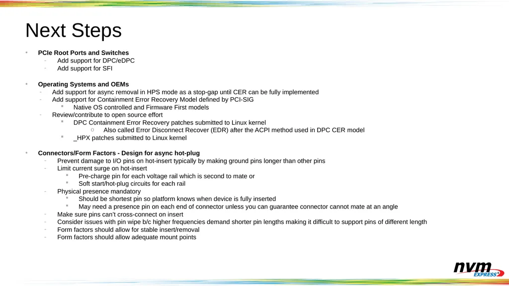
Next Steps PCIe Root Ports and Switches
Add support for DPC/eDPC
Add support for SFI
Operating Systems and OEMs
Add support for async removal in HPS mode as a stop-gap until CER can be fully implemented
Add support for Containment Error Recovery Model defined by PCI-SIG
Native OS controlled and Firmware First models
Review/contribute to open source effort
DPC Containment Error Recovery patches submitted to Linux kernel
Also called Error Disconnect Recover (EDR) after the ACPI method used in DPC CER model
_HPX patches submitted to Linux kernel
Connectors/Form Factors - Design for async hot-plug
Prevent damage to I/O pins on hot-insert typically by making ground pins longer than other pins
Limit current surge on hot-insert
Pre-charge pin for each voltage rail which is second to mate or
Soft start/hot-plug circuits for each rail
Physical presence mandatory
Should be shortest pin so platform knows when device is fully inserted
May need a presence pin on each end of connector unless you can guarantee connector cannot mate at an angle
Make sure pins can’t cross-connect on insert
Consider issues with pin wipe b/c higher frequencies demand shorter pin lengths making it difficult to support pins of different length
Form factors should allow for stable insert/removal
Form factors should allow adequate mount points<br>
Add support for DPC/eDPC
Add support for SFI
Operating Systems and OEMs
Add support for async removal in HPS mode as a stop-gap until CER can be fully implemented
Add support for Containment Error Recovery Model defined by PCI-SIG
Native OS controlled and Firmware First models
Review/contribute to open source effort
DPC Containment Error Recovery patches submitted to Linux kernel
Also called Error Disconnect Recover (EDR) after the ACPI method used in DPC CER model
_HPX patches submitted to Linux kernel
Connectors/Form Factors - Design for async hot-plug
Prevent damage to I/O pins on hot-insert typically by making ground pins longer than other pins
Limit current surge on hot-insert
Pre-charge pin for each voltage rail which is second to mate or
Soft start/hot-plug circuits for each rail
Physical presence mandatory
Should be shortest pin so platform knows when device is fully inserted
May need a presence pin on each end of connector unless you can guarantee connector cannot mate at an angle
Make sure pins can’t cross-connect on insert
Consider issues with pin wipe b/c higher frequencies demand shorter pin lengths making it difficult to support pins of different length
Form factors should allow for stable insert/removal
Form factors should allow adequate mount points<br>
23
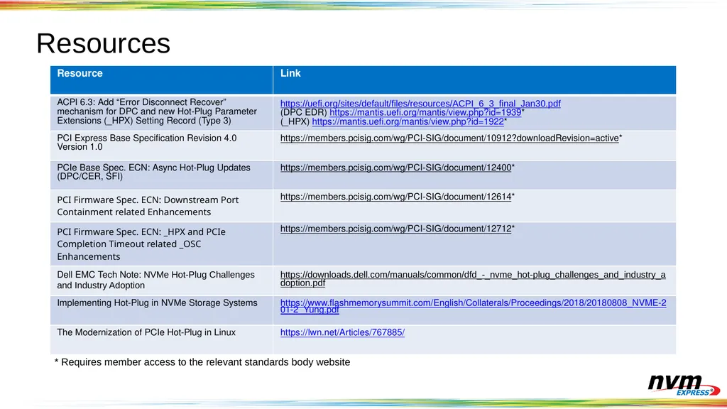
Resources * Requires member access to the relevant standards body website<br>
24
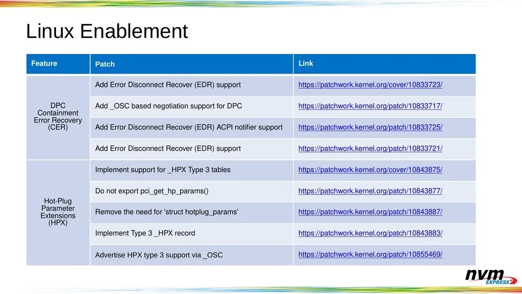
Linux Enablement<br>
25
Questions?<br>