01
SI for Free: Machine Learning of Interconnect Coupling Delay and Transition Effects Andrew B. Kahng‡†, Mulong Luo†, Siddhartha Nath†
‡† ECE and †CSE Departments, UC San Diego
{abk, muluo, sinath}@ucsd.edu<br>
04
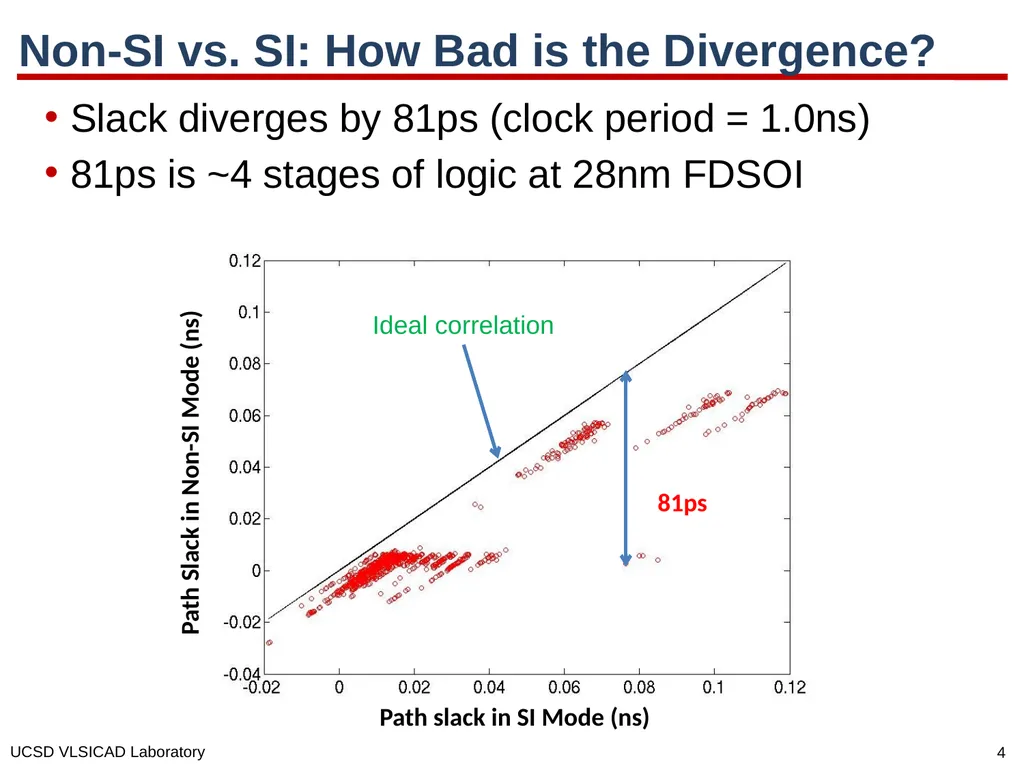
Non-SI vs. SI: How Bad is the Divergence? Slack diverges by 81ps (clock period = 1.0ns)
81ps is ~4 stages of logic at 28nm FDSOI 81ps Path slack in SI Mode (ns) Path Slack in Non-SI Mode (ns) Ideal correlation<br>
05
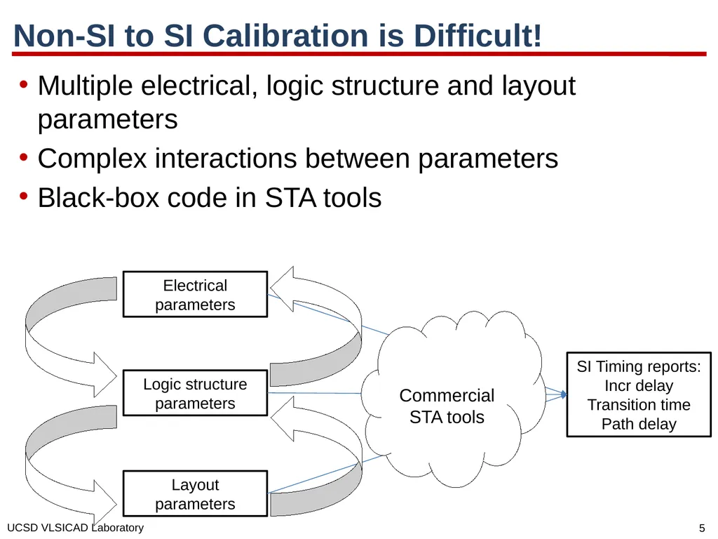
Non-SI to SI Calibration is Difficult! Multiple electrical, logic structure and layout parameters
Complex interactions between parameters
Black-box code in STA tools Electrical parameters Logic structure parameters Layout parameters SI Timing reports:
Incr delay
Transition time
Path delay Commercial STA tools<br>
06
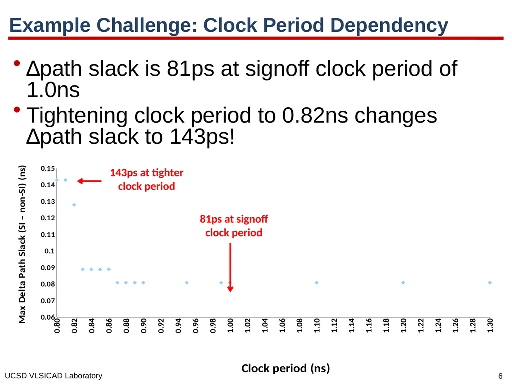
Example Challenge: Clock Period Dependency ∆path slack is 81ps at signoff clock period of 1.0ns
Tightening clock period to 0.82ns changes ∆path slack to 143ps! 81ps at signoff clock period 143ps at tighter clock period<br>
07
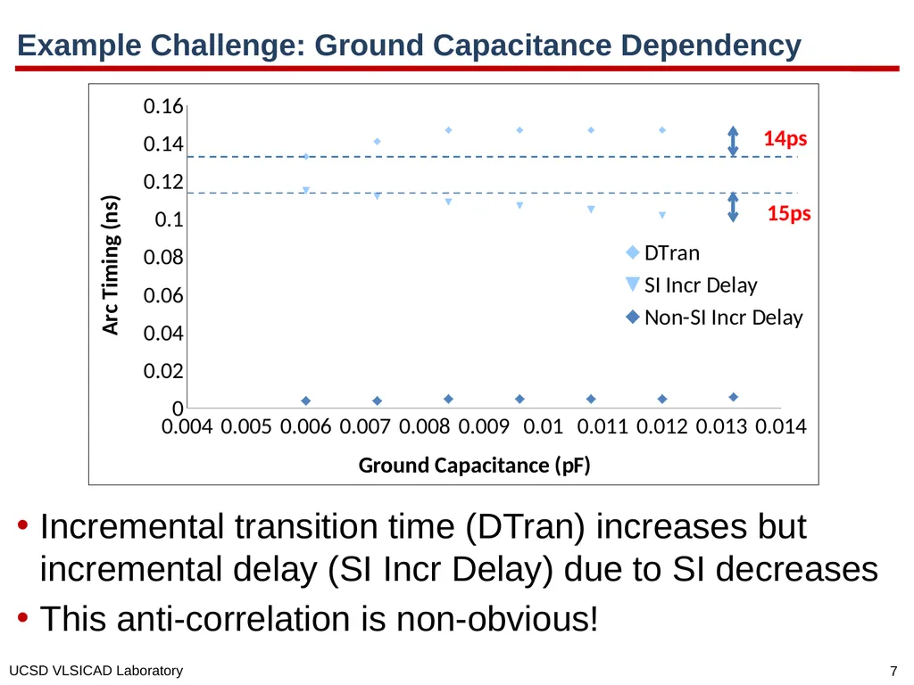
Example Challenge: Ground Capacitance Dependency Incremental transition time (DTran) increases but incremental delay (SI Incr Delay) due to SI decreases
This anti-correlation is non-obvious! 14ps 15ps<br>
08
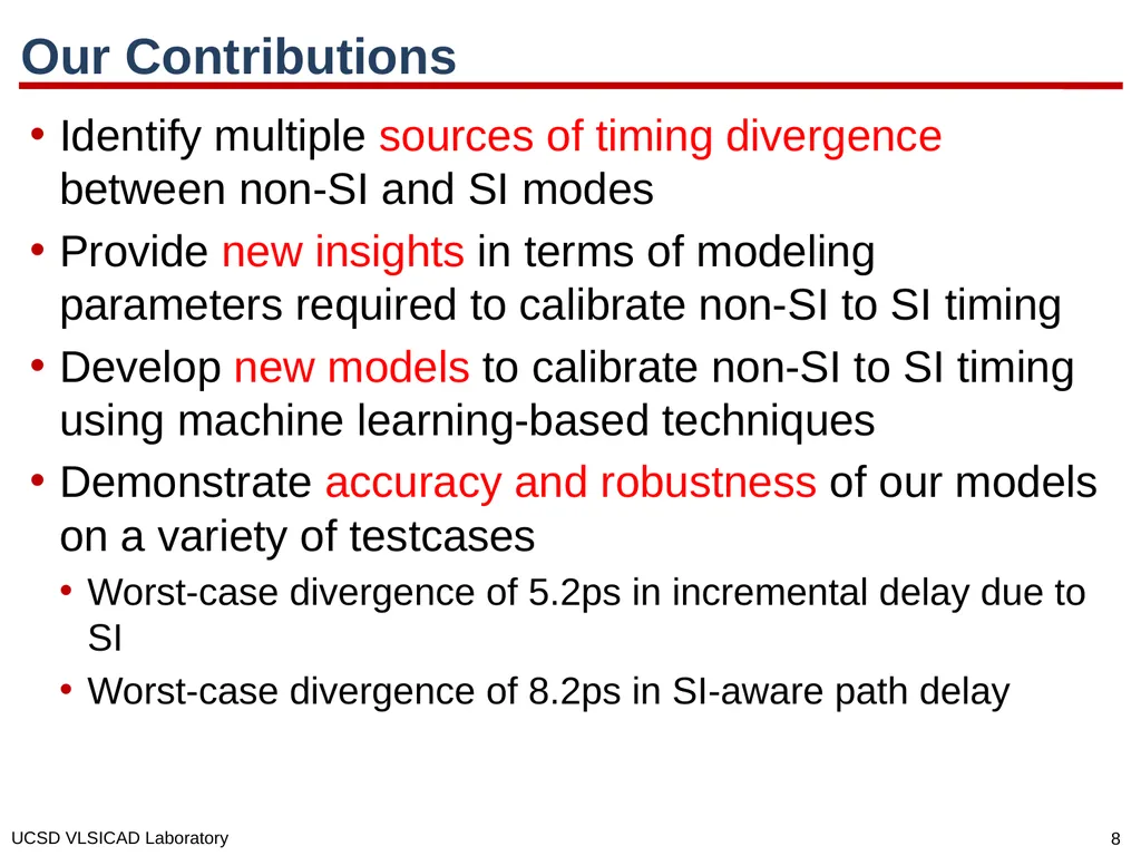
Our Contributions Identify multiple sources of timing divergence between non-SI and SI modes
Provide new insights in terms of modeling parameters required to calibrate non-SI to SI timing
Develop new models to calibrate non-SI to SI timing using machine learning-based techniques
Demonstrate accuracy and robustness of our models on a variety of testcases
Worst-case divergence of 5.2ps in incremental delay due to SI
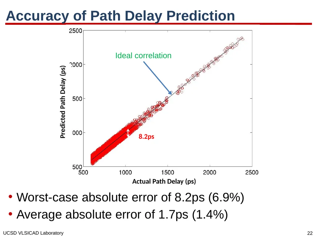
Worst-case divergence of 8.2ps in SI-aware path delay<br>
09
Outline Motivation
Previous Work
Our Methodology and Accuracy Results
Design of Experiments and Robustness Results
Conclusions<br>
10
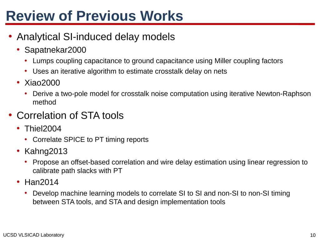
Review of Previous Works Analytical SI-induced delay models
Sapatnekar2000
Lumps coupling capacitance to ground capacitance using Miller coupling factors
Uses an iterative algorithm to estimate crosstalk delay on nets
Xiao2000
Derive a two-pole model for crosstalk noise computation using iterative Newton-Raphson method
Correlation of STA tools
Thiel2004
Correlate SPICE to PT timing reports
Kahng2013
Propose an offset-based correlation and wire delay estimation using linear regression to calibrate path slacks with PT
Han2014
Develop machine learning models to correlate SI to SI and non-SI to non-SI timing between STA tools, and STA and design implementation tools<br>
11
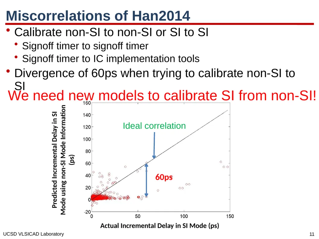
Miscorrelations of Han2014 Calibrate non-SI to non-SI or SI to SI
Signoff timer to signoff timer
Signoff timer to IC implementation tools
Divergence of 60ps when trying to calibrate non-SI to SI We need new models to calibrate SI from non-SI!<br>
12
Outline Motivation
Previous Work
Our Methodology and Accuracy Results
Design of Experiments and Robustness Results
Conclusions<br>
13
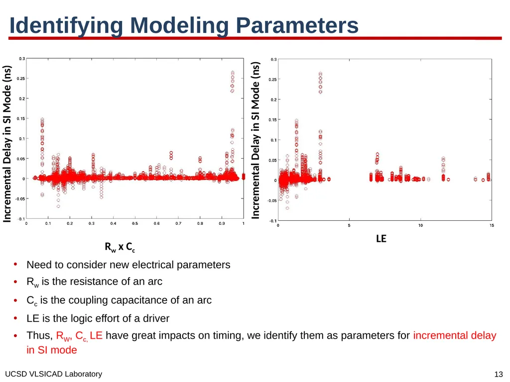
Identifying Modeling Parameters Need to consider new electrical parameters
Rw is the resistance of an arc
Cc is the coupling capacitance of an arc
LE is the logic effort of a driver
Thus, RW, Cc, LE have great impacts on timing, we identify them as parameters for incremental delay in SI mode Rw x Cc Incremental Delay in SI Mode (ns) LE Incremental Delay in SI Mode (ns)<br>
14
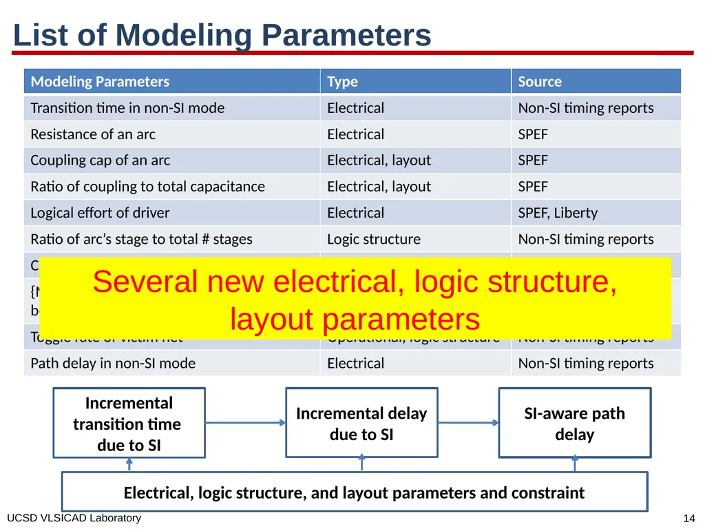
List of Modeling Parameters Incremental transition time due to SI Incremental delay due to SI SI-aware path delay Electrical, logic structure, and layout parameters and constraint Several new electrical, logic structure, layout parameters<br>
15
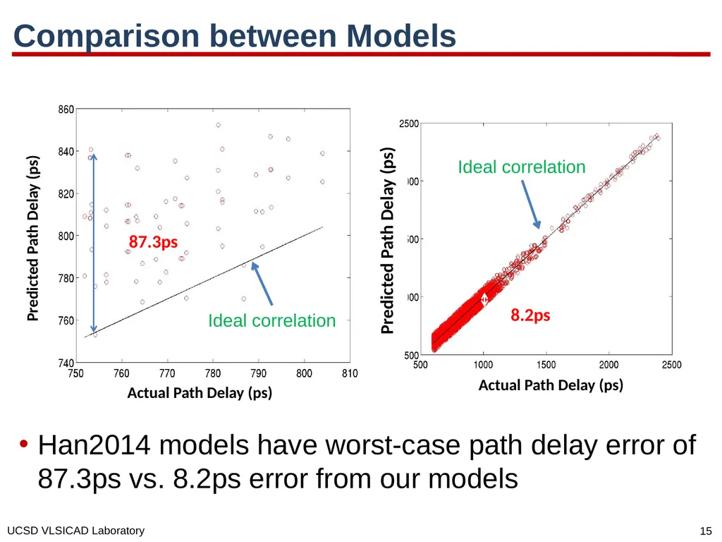
Comparison between Models Han2014 models have worst-case path delay error of 87.3ps vs. 8.2ps error from our models<br>
16
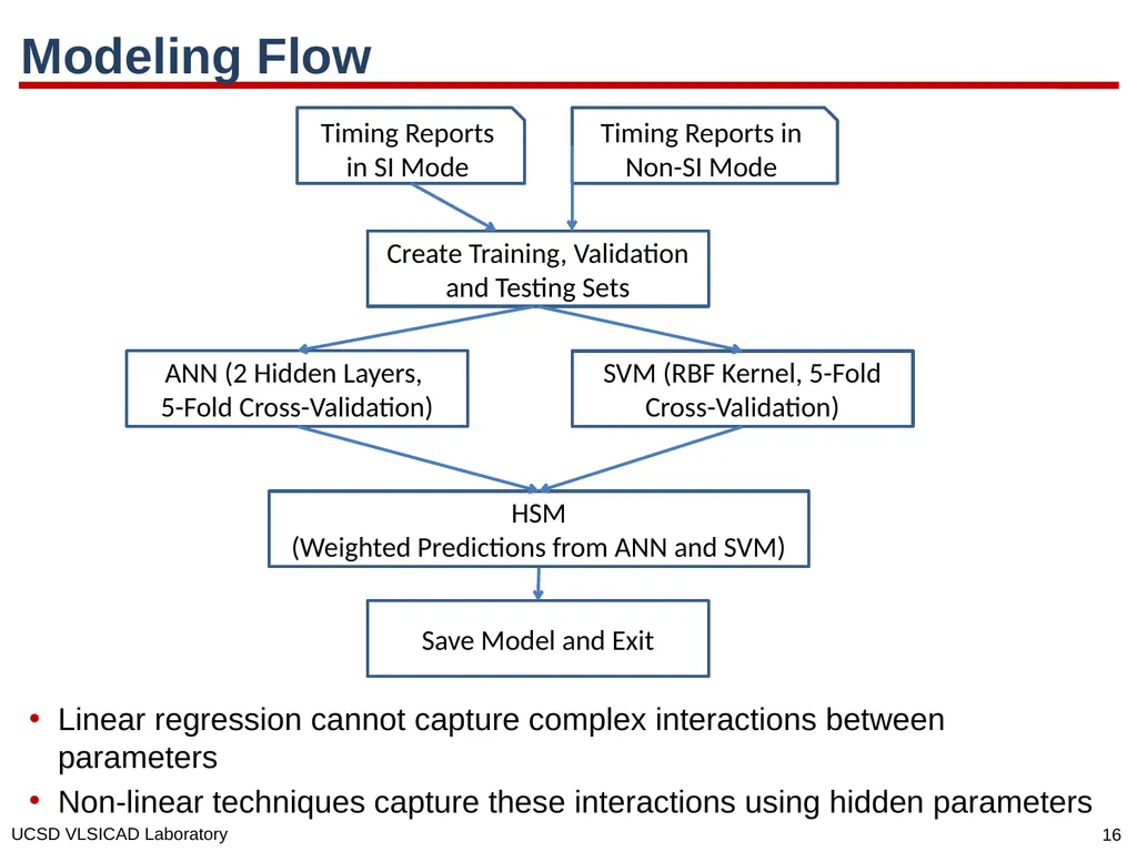
Modeling Flow Timing Reports in SI Mode Timing Reports in Non-SI Mode Create Training, Validation and Testing Sets ANN (2 Hidden Layers,
5-Fold Cross-Validation) Save Model and Exit SVM (RBF Kernel, 5-Fold Cross-Validation) HSM
(Weighted Predictions from ANN and SVM) Linear regression cannot capture complex interactions between parameters
Non-linear techniques capture these interactions using hidden parameters<br>
17
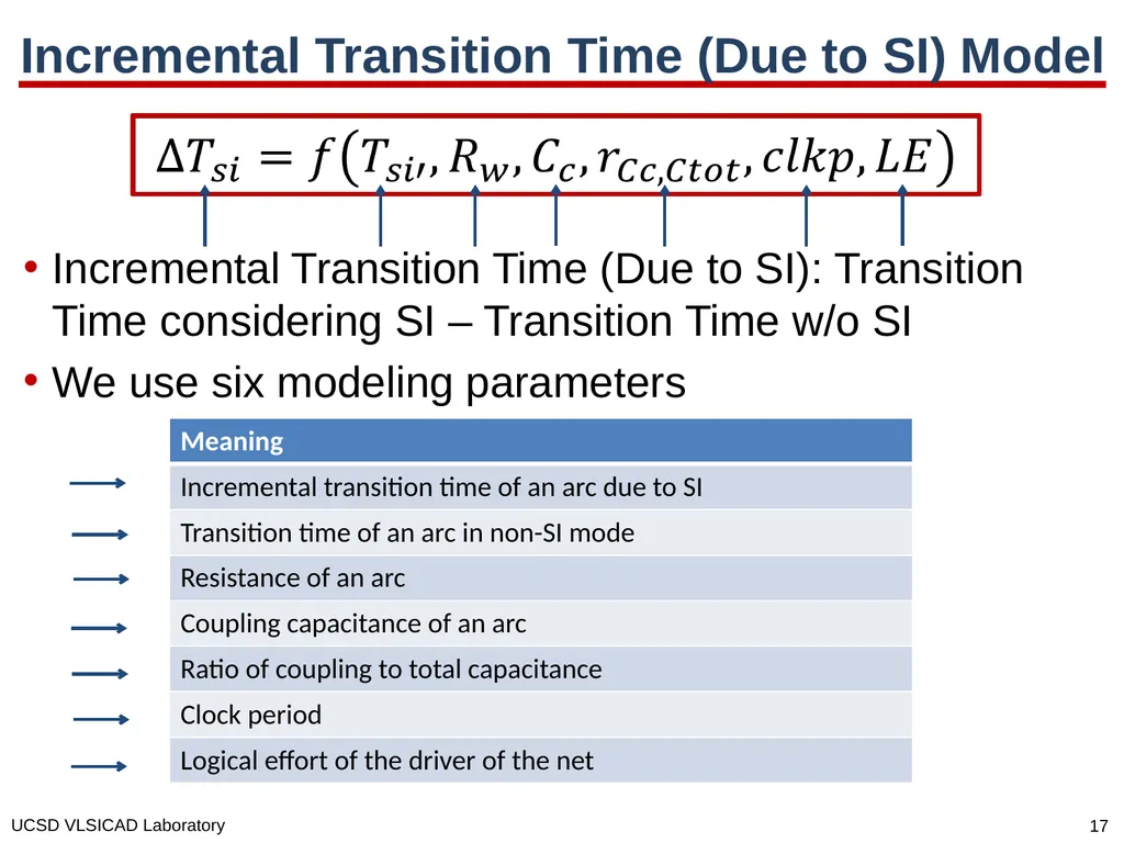
Incremental Transition Time (Due to SI) Model Incremental Transition Time (Due to SI): Transition Time considering SI – Transition Time w/o SI
We use six modeling parameters<br>
18
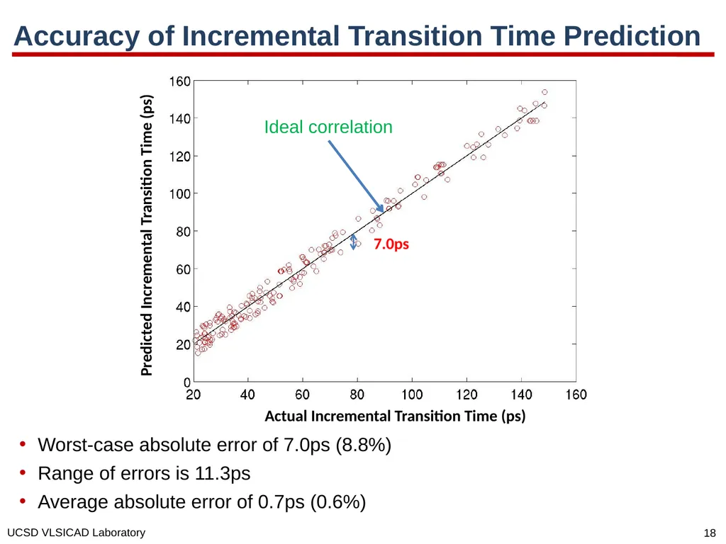
Accuracy of Incremental Transition Time Prediction Worst-case absolute error of 7.0ps (8.8%)
Range of errors is 11.3ps
Average absolute error of 0.7ps (0.6%) Actual Incremental Transition Time (ps) Predicted Incremental Transition Time (ps) 7.0ps Ideal correlation<br>
19
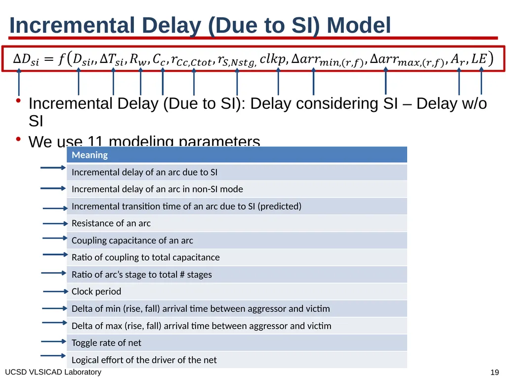
Incremental Delay (Due to SI) Model Incremental Delay (Due to SI): Delay considering SI – Delay w/o SI
We use 11 modeling parameters<br>
20
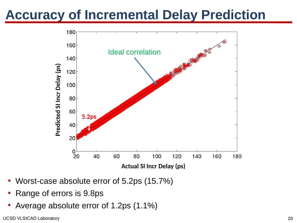
Accuracy of Incremental Delay Prediction Worst-case absolute error of 5.2ps (15.7%)
Range of errors is 9.8ps
Average absolute error of 1.2ps (1.1%) Actual SI Incr Delay (ps) Predicted SI Incr Delay (ps) 5.2ps Ideal correlation<br>
21
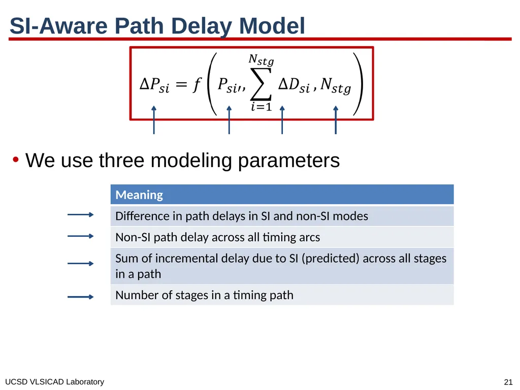
SI-Aware Path Delay Model We use three modeling parameters<br>
22
Accuracy of Path Delay Prediction Worst-case absolute error of 8.2ps (6.9%)
Average absolute error of 1.7ps (1.4%) Actual Path Delay (ps) Predicted Path Delay (ps) 8.2ps Ideal correlation<br>
23
Outline Motivation
Previous Work
Our Methodology and Accuracy Results
Design of Experiments and Robustness Results
Conclusions<br>
24
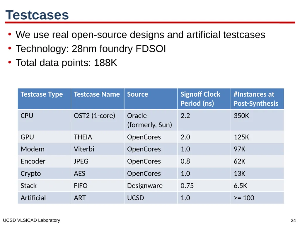
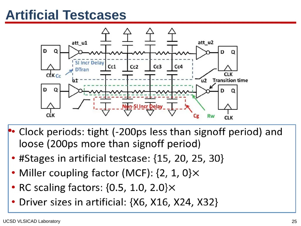
Testcases We use real open-source designs and artificial testcases
Technology: 28nm foundry FDSOI
Total data points: 188K<br>
25
Artificial Testcases<br>
26
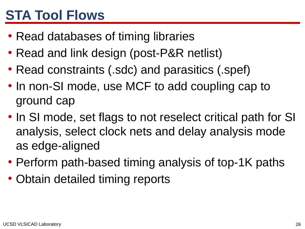
STA Tool Flows Read databases of timing libraries
Read and link design (post-P&R netlist)
Read constraints (.sdc) and parasitics (.spef)
In non-SI mode, use MCF to add coupling cap to ground cap
In SI mode, set flags to not reselect critical path for SI analysis, select clock nets and delay analysis mode as edge-aligned
Perform path-based timing analysis of top-1K paths
Obtain detailed timing reports<br>
27
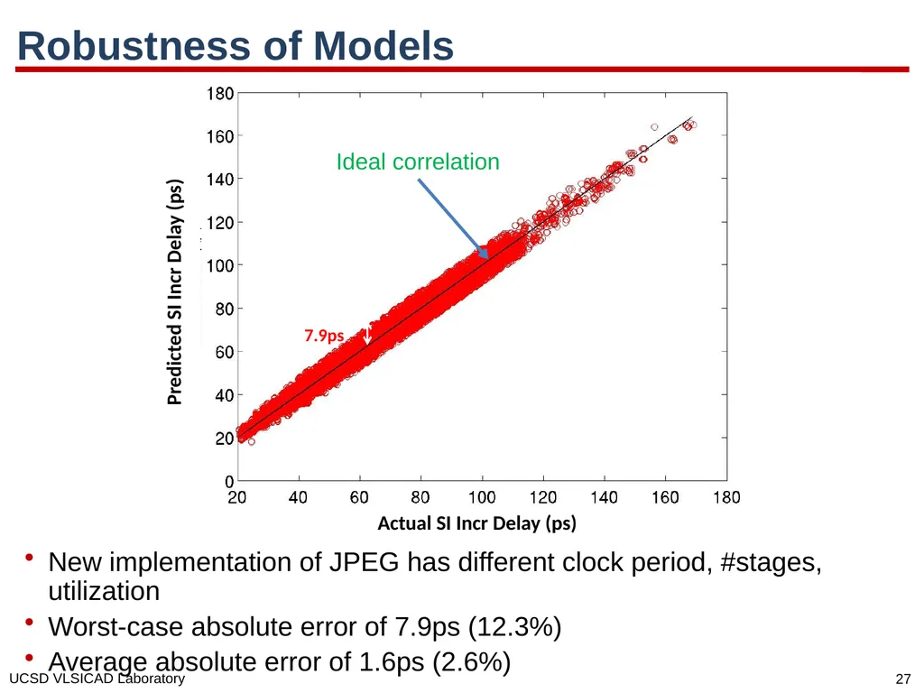
Robustness of Models New implementation of JPEG has different clock period, #stages, utilization
Worst-case absolute error of 7.9ps (12.3%)
Average absolute error of 1.6ps (2.6%) Actual SI Incr Delay (ps) Predicted SI Incr Delay (ps) 7.9ps Ideal correlation<br>
28
Outline Motivation
Previous Work
Our Methodology and Accuracy Results
Design of Experiments and Robustness Results
Conclusions<br>
29
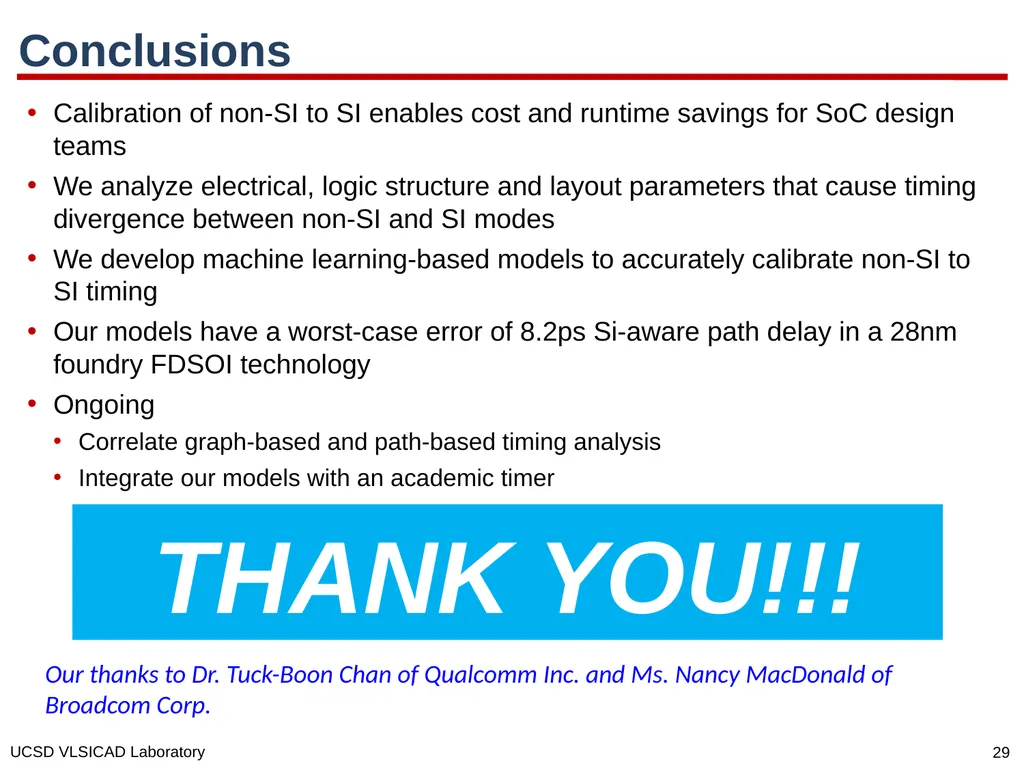
Conclusions Calibration of non-SI to SI enables cost and runtime savings for SoC design teams
We analyze electrical, logic structure and layout parameters that cause timing divergence between non-SI and SI modes
We develop machine learning-based models to accurately calibrate non-SI to SI timing
Our models have a worst-case error of 8.2ps Si-aware path delay in a 28nm foundry FDSOI technology
Ongoing
Correlate graph-based and path-based timing analysis
Integrate our models with an academic timer THANK YOU!!! Our thanks to Dr. Tuck-Boon Chan of Qualcomm Inc. and Ms. Nancy MacDonald of Broadcom Corp.<br>
31
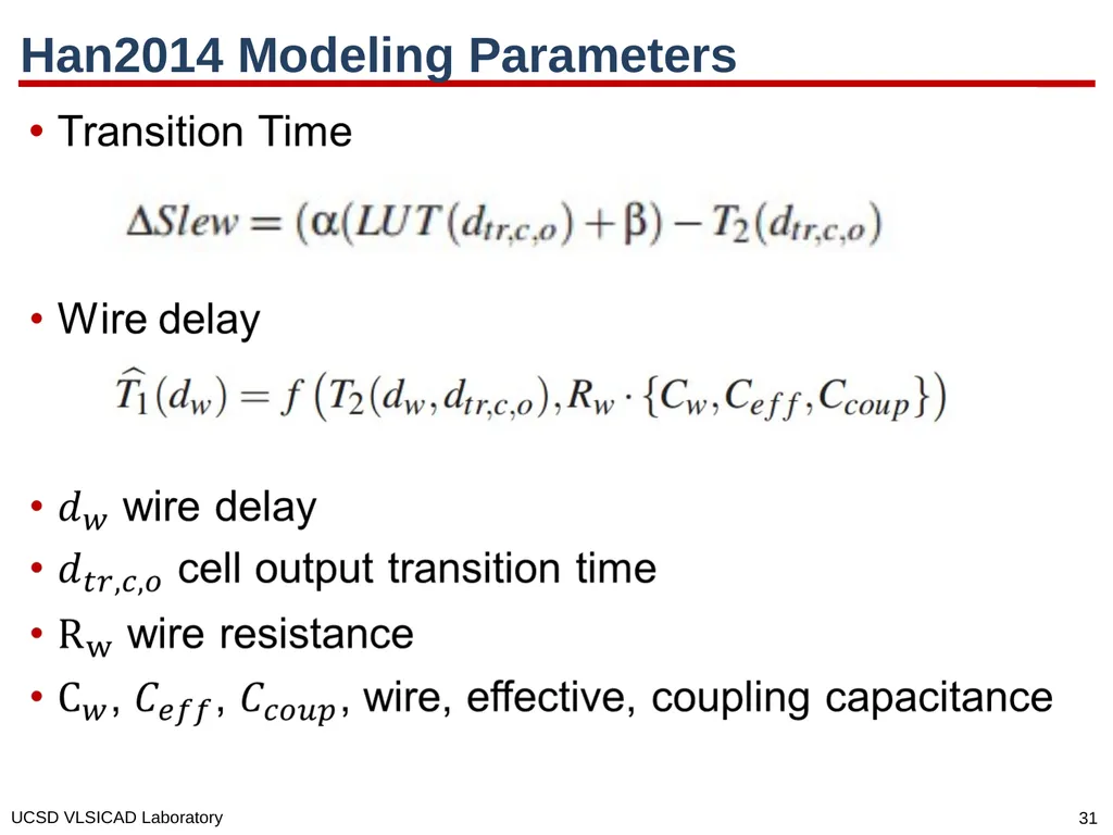
Han2014 Modeling Parameters<br>
32
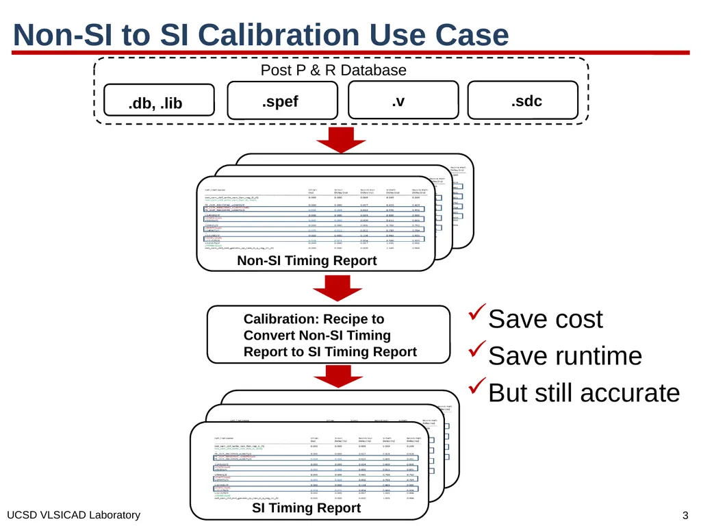
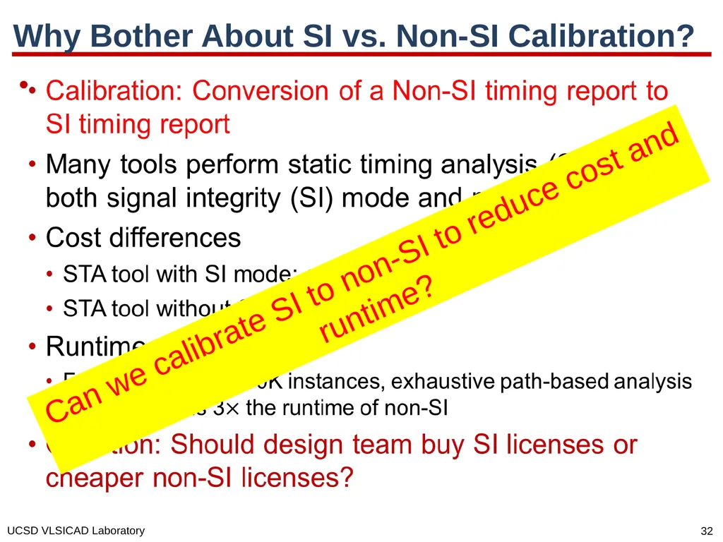
Why Bother About SI vs. Non-SI Calibration? Can we calibrate SI to non-SI to reduce cost and runtime?<br>