
The design & progress of bunch by bunch
TD
Published · 36 slides · 0 views

1 / 1


Description
The design progress of bunch by bunch measurement system for HIAF Min Li, Ruishi Mao, Tiecheng Zhao, Yongliang Yang, Yonggan Nie, Yucong Chen, Weilong Li, Shengpeng Li, Xiaojuan Wei Email: liminimpcas.ac.cn Beam diagnostics department
Related Topics
Share
Embed code
Download this presentation From Below
"The design & progress of bunch by bunch" is the property of its rightful owner. Permission is granted to download and print the materials on this website for personal, non-commercial use only, and to display it on your personal computer provided you do not modify the materials and that you retain all copyright notices contained in the materials. By downloading content from our website, you accept the terms of this agreement.
Presentation Transcript
01
The design & progress of bunch by bunch measurement system for HIAF Min Li, Ruishi Mao, Tiecheng Zhao, Yongliang Yang, Yonggan Nie, Yucong Chen, Weilong Li, Shengpeng Li, Xiaojuan Wei
Email: limin@impcas.ac.cn
Beam diagnostics department
Institute of Modern Physics, Chinese Academy of Science Next Generation Beam Position Acquisition and Feedback Systems, Barcelona - Spain<br>
Email: limin@impcas.ac.cn
Beam diagnostics department
Institute of Modern Physics, Chinese Academy of Science Next Generation Beam Position Acquisition and Feedback Systems, Barcelona - Spain<br>
02
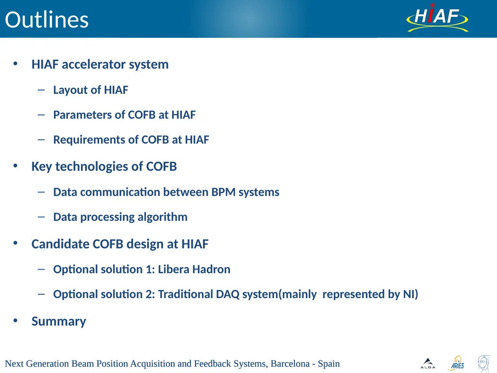
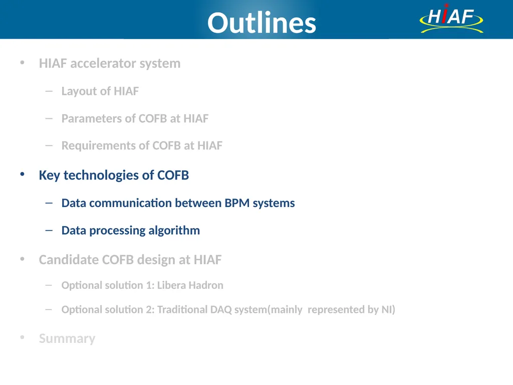
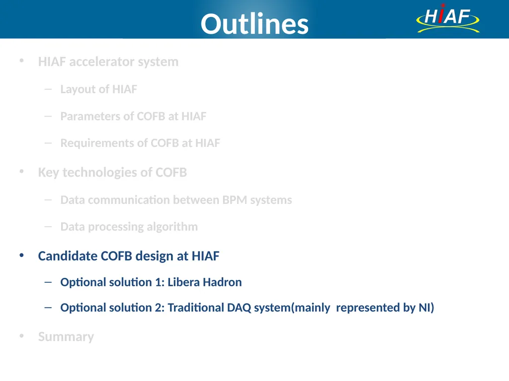
Outlines HIAF accelerator system
Layout of HIAF
Parameters of COFB at HIAF
Requirements of COFB at HIAF
Key technologies of COFB
Data communication between BPM systems
Data processing algorithm
Candidate COFB design at HIAF
Optional solution 1: Libera Hadron
Optional solution 2: Traditional DAQ system(mainly represented by NI)
Summary Next Generation Beam Position Acquisition and Feedback Systems, Barcelona - Spain<br>
Layout of HIAF
Parameters of COFB at HIAF
Requirements of COFB at HIAF
Key technologies of COFB
Data communication between BPM systems
Data processing algorithm
Candidate COFB design at HIAF
Optional solution 1: Libera Hadron
Optional solution 2: Traditional DAQ system(mainly represented by NI)
Summary Next Generation Beam Position Acquisition and Feedback Systems, Barcelona - Spain<br>
03
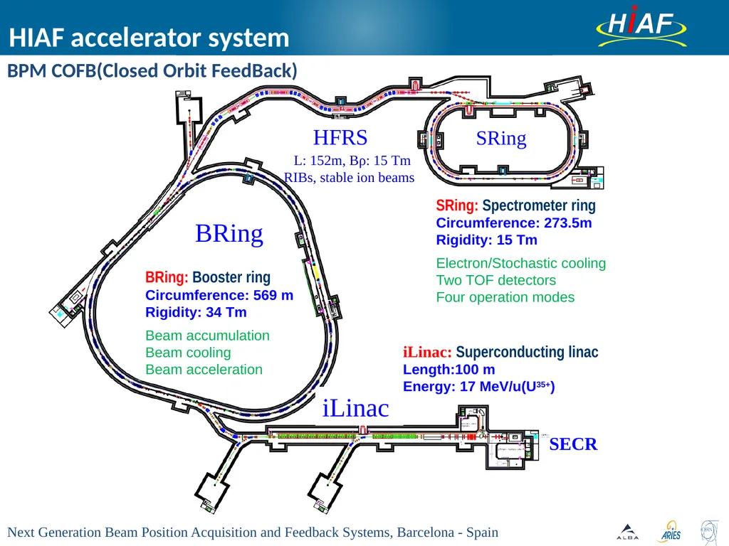
HIAF accelerator system BPM COFB(Closed Orbit FeedBack)<br>
04
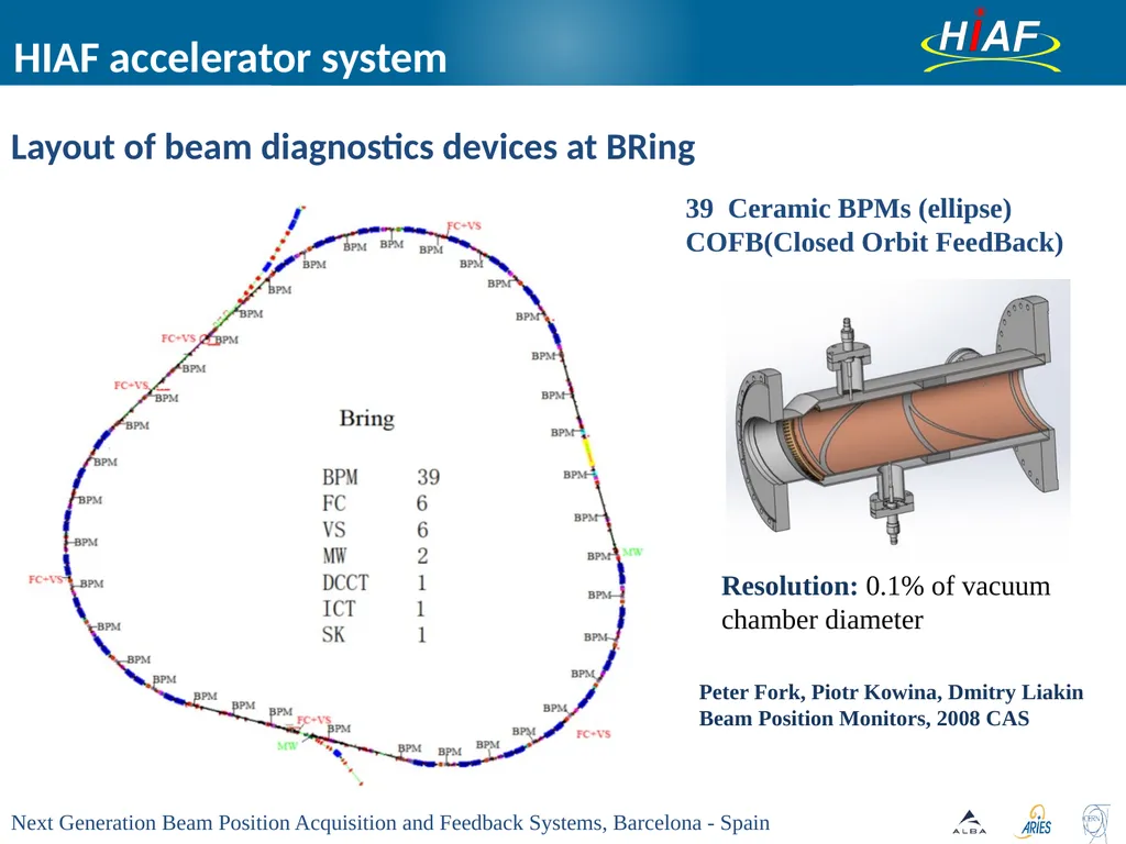
HIAF accelerator system 39 Ceramic BPMs (ellipse)
COFB(Closed Orbit FeedBack) Layout of beam diagnostics devices at BRing Resolution: 0.1% of vacuum chamber diameter Peter Fork, Piotr Kowina, Dmitry Liakin
Beam Position Monitors, 2008 CAS<br>
COFB(Closed Orbit FeedBack) Layout of beam diagnostics devices at BRing Resolution: 0.1% of vacuum chamber diameter Peter Fork, Piotr Kowina, Dmitry Liakin
Beam Position Monitors, 2008 CAS<br>
05
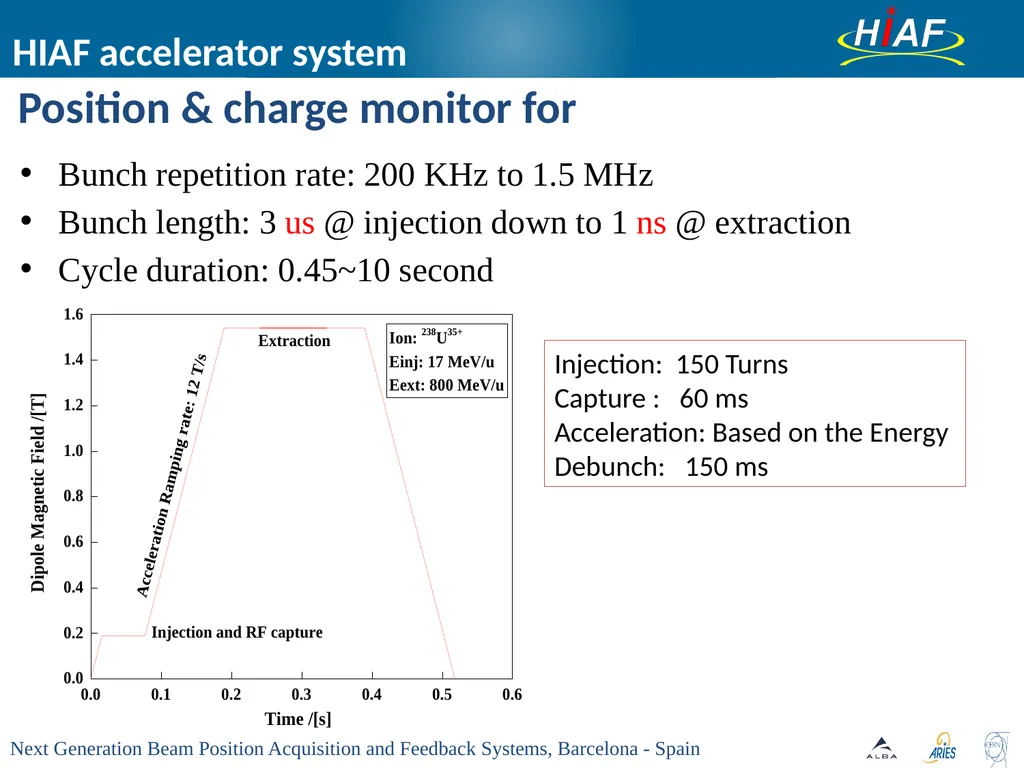
HIAF accelerator system Position & charge monitor for Bunch repetition rate: 200 KHz to 1.5 MHz
Bunch length: 3 us @ injection down to 1 ns @ extraction
Cycle duration: 0.45~10 second Injection: 150 Turns
Capture : 60 ms
Acceleration: Based on the Energy
Debunch: 150 ms<br>
Bunch length: 3 us @ injection down to 1 ns @ extraction
Cycle duration: 0.45~10 second Injection: 150 Turns
Capture : 60 ms
Acceleration: Based on the Energy
Debunch: 150 ms<br>
06
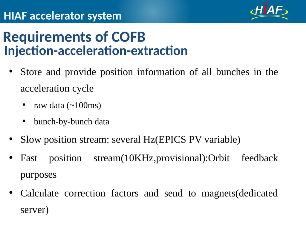
Store and provide position information of all bunches in the acceleration cycle
raw data (~100ms)
bunch-by-bunch data
Slow position stream: several Hz(EPICS PV variable)
Fast position stream(10KHz,provisional):Orbit feedback purposes
Calculate correction factors and send to magnets(dedicated server) Requirements of COFB Injection-acceleration-extraction HIAF accelerator system<br>
raw data (~100ms)
bunch-by-bunch data
Slow position stream: several Hz(EPICS PV variable)
Fast position stream(10KHz,provisional):Orbit feedback purposes
Calculate correction factors and send to magnets(dedicated server) Requirements of COFB Injection-acceleration-extraction HIAF accelerator system<br>
07
Outlines HIAF accelerator system
Layout of HIAF
Parameters of COFB at HIAF
Requirements of COFB at HIAF
Key technologies of COFB
Data communication between BPM systems
Data processing algorithm
Candidate COFB design at HIAF
Optional solution 1: Libera Hadron
Optional solution 2: Traditional DAQ system(mainly represented by NI)
Summary<br>
Layout of HIAF
Parameters of COFB at HIAF
Requirements of COFB at HIAF
Key technologies of COFB
Data communication between BPM systems
Data processing algorithm
Candidate COFB design at HIAF
Optional solution 1: Libera Hadron
Optional solution 2: Traditional DAQ system(mainly represented by NI)
Summary<br>
08
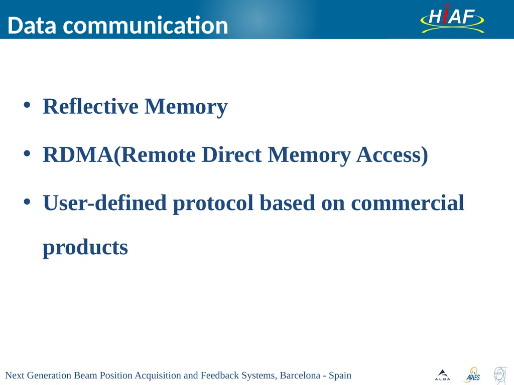
Data communication Reflective Memory
RDMA(Remote Direct Memory Access)
User-defined protocol based on commercial products<br>
RDMA(Remote Direct Memory Access)
User-defined protocol based on commercial products<br>
09
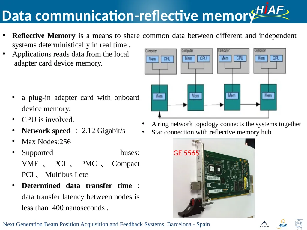
Data communication-reflective memory Reflective Memory is a means to share common data between different and independent systems deterministically in real time .
Applications reads data from the local
adapter card device memory. a plug-in adapter card with onboard device memory.
CPU is involved.
Network speed:2.12 Gigabit/s
Max Nodes:256
Supported buses: VME、PCI、PMC、Compact PCI、Multibus I etc
Determined data transfer time : data transfer latency between nodes is less than 400 nanoseconds . A ring network topology connects the systems together
Star connection with reflective memory hub GE 5565<br>
Applications reads data from the local
adapter card device memory. a plug-in adapter card with onboard device memory.
CPU is involved.
Network speed:2.12 Gigabit/s
Max Nodes:256
Supported buses: VME、PCI、PMC、Compact PCI、Multibus I etc
Determined data transfer time : data transfer latency between nodes is less than 400 nanoseconds . A ring network topology connects the systems together
Star connection with reflective memory hub GE 5565<br>
10
The arrangement of all 54 BPM signal processor units in RCS [1]N. Hayashi, M. Kawase et.al, Beam position monitor system of J-PARC RCS, Nuclear Instruments and Methods in Physics Research A 677 (2012) 94–106 Zhenghong hangke in Shanxi Province:produce the reflective memory cards with all the supported buses and is compatible with GE 5565 completely.
http://zhhktech.jdol.com.cn/
Shenzhou feihang in Beijing : produce reflective memory cards with custom bus, has the ability of developing the FGPA IP core for reflective memory
http://www.senfetech.com/nav/1.html Laboratory test HIRFL-TR4 test with beam Sender Receiver Data communication-reflective memory<br>
http://zhhktech.jdol.com.cn/
Shenzhou feihang in Beijing : produce reflective memory cards with custom bus, has the ability of developing the FGPA IP core for reflective memory
http://www.senfetech.com/nav/1.html Laboratory test HIRFL-TR4 test with beam Sender Receiver Data communication-reflective memory<br>
11
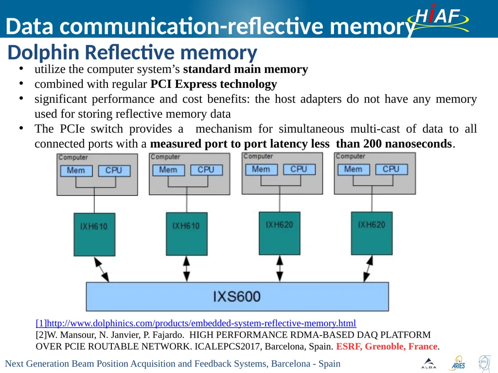
Dolphin Reflective memory Data communication-reflective memory utilize the computer system’s standard main memory
combined with regular PCI Express technology
significant performance and cost benefits: the host adapters do not have any memory used for storing reflective memory data
The PCIe switch provides a mechanism for simultaneous multi-cast of data to all connected ports with a measured port to port latency less than 200 nanoseconds. [1]http://www.dolphinics.com/products/embedded-system-reflective-memory.html
[2]W. Mansour, N. Janvier, P. Fajardo. HIGH PERFORMANCE RDMA-BASED DAQ PLATFORM OVER PCIE ROUTABLE NETWORK. ICALEPCS2017, Barcelona, Spain. ESRF, Grenoble, France.<br>
combined with regular PCI Express technology
significant performance and cost benefits: the host adapters do not have any memory used for storing reflective memory data
The PCIe switch provides a mechanism for simultaneous multi-cast of data to all connected ports with a measured port to port latency less than 200 nanoseconds. [1]http://www.dolphinics.com/products/embedded-system-reflective-memory.html
[2]W. Mansour, N. Janvier, P. Fajardo. HIGH PERFORMANCE RDMA-BASED DAQ PLATFORM OVER PCIE ROUTABLE NETWORK. ICALEPCS2017, Barcelona, Spain. ESRF, Grenoble, France.<br>
12
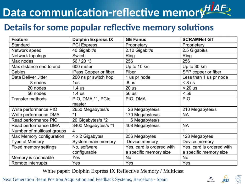
Details for some popular reflective memory solutions Data communication-reflective memory White paper: Dolphin Express IX Reflective Memory / Multicast<br>
13
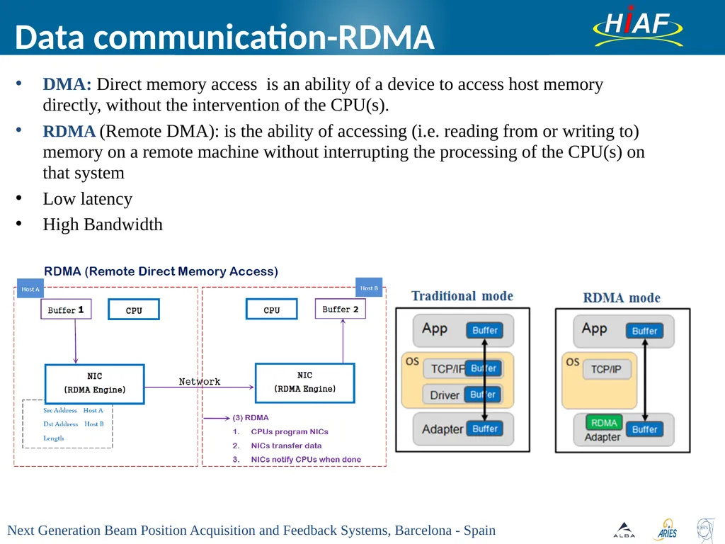
Data communication-RDMA DMA: Direct memory access is an ability of a device to access host memory directly, without the intervention of the CPU(s).
RDMA (Remote DMA): is the ability of accessing (i.e. reading from or writing to) memory on a remote machine without interrupting the processing of the CPU(s) on that system
Low latency
High Bandwidth<br>
RDMA (Remote DMA): is the ability of accessing (i.e. reading from or writing to) memory on a remote machine without interrupting the processing of the CPU(s) on that system
Low latency
High Bandwidth<br>
14
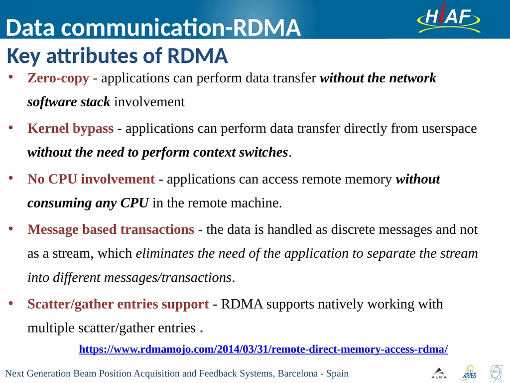
Key attributes of RDMA Data communication-RDMA Zero-copy - applications can perform data transfer without the network software stack involvement
Kernel bypass - applications can perform data transfer directly from userspace without the need to perform context switches.
No CPU involvement - applications can access remote memory without consuming any CPU in the remote machine.
Message based transactions - the data is handled as discrete messages and not as a stream, which eliminates the need of the application to separate the stream into different messages/transactions.
Scatter/gather entries support - RDMA supports natively working with multiple scatter/gather entries . https://www.rdmamojo.com/2014/03/31/remote-direct-memory-access-rdma/<br>
Kernel bypass - applications can perform data transfer directly from userspace without the need to perform context switches.
No CPU involvement - applications can access remote memory without consuming any CPU in the remote machine.
Message based transactions - the data is handled as discrete messages and not as a stream, which eliminates the need of the application to separate the stream into different messages/transactions.
Scatter/gather entries support - RDMA supports natively working with multiple scatter/gather entries . https://www.rdmamojo.com/2014/03/31/remote-direct-memory-access-rdma/<br>
15
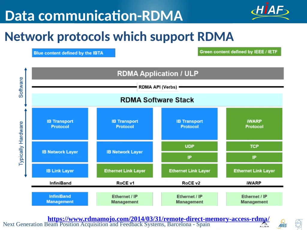
Network protocols which support RDMA Data communication-RDMA https://www.rdmamojo.com/2014/03/31/remote-direct-memory-access-rdma/<br>
16
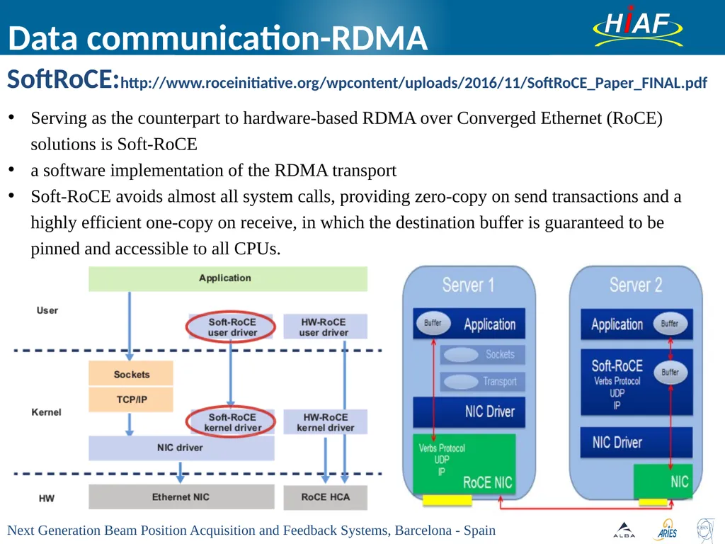
SoftRoCE:http://www.roceinitiative.org/wpcontent/uploads/2016/11/SoftRoCE_Paper_FINAL.pdf Data communication-RDMA Serving as the counterpart to hardware-based RDMA over Converged Ethernet (RoCE) solutions is Soft-RoCE
a software implementation of the RDMA transport
Soft-RoCE avoids almost all system calls, providing zero-copy on send transactions and a highly efficient one-copy on receive, in which the destination buffer is guaranteed to be pinned and accessible to all CPUs.<br>
a software implementation of the RDMA transport
Soft-RoCE avoids almost all system calls, providing zero-copy on send transactions and a highly efficient one-copy on receive, in which the destination buffer is guaranteed to be pinned and accessible to all CPUs.<br>
17
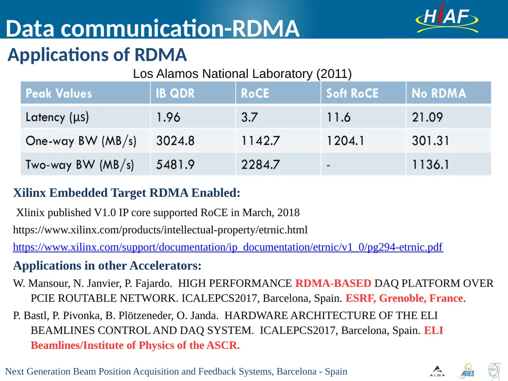
Applications of RDMA Data communication-RDMA Xilinx Embedded Target RDMA Enabled:
Xlinix published V1.0 IP core supported RoCE in March, 2018
https://www.xilinx.com/products/intellectual-property/etrnic.html
https://www.xilinx.com/support/documentation/ip_documentation/etrnic/v1_0/pg294-etrnic.pdf
Applications in other Accelerators:
W. Mansour, N. Janvier, P. Fajardo. HIGH PERFORMANCE RDMA-BASED DAQ PLATFORM OVER PCIE ROUTABLE NETWORK. ICALEPCS2017, Barcelona, Spain. ESRF, Grenoble, France.
P. Bastl, P. Pivonka, B. Plötzeneder, O. Janda. HARDWARE ARCHITECTURE OF THE ELI BEAMLINES CONTROL AND DAQ SYSTEM. ICALEPCS2017, Barcelona, Spain. ELI Beamlines/Institute of Physics of the ASCR. Los Alamos National Laboratory (2011)<br>
Xlinix published V1.0 IP core supported RoCE in March, 2018
https://www.xilinx.com/products/intellectual-property/etrnic.html
https://www.xilinx.com/support/documentation/ip_documentation/etrnic/v1_0/pg294-etrnic.pdf
Applications in other Accelerators:
W. Mansour, N. Janvier, P. Fajardo. HIGH PERFORMANCE RDMA-BASED DAQ PLATFORM OVER PCIE ROUTABLE NETWORK. ICALEPCS2017, Barcelona, Spain. ESRF, Grenoble, France.
P. Bastl, P. Pivonka, B. Plötzeneder, O. Janda. HARDWARE ARCHITECTURE OF THE ELI BEAMLINES CONTROL AND DAQ SYSTEM. ICALEPCS2017, Barcelona, Spain. ELI Beamlines/Institute of Physics of the ASCR. Los Alamos National Laboratory (2011)<br>
18
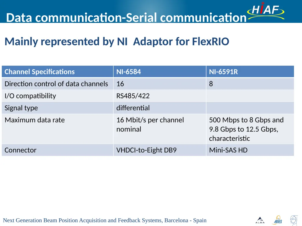
Mainly represented by NI Adaptor for FlexRIO Data communication-Serial communication<br>
19
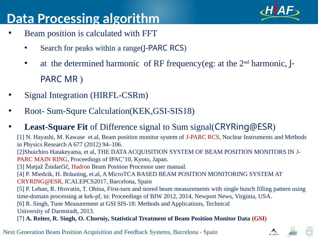
Data Processing algorithm Beam position is calculated with FFT
Search for peaks within a range(J-PARC RCS)
at the determined harmonic of RF frequency(eg: at the 2nd harmonic, J-PARC MR )
Signal Integration (HIRFL-CSRm)
Root- Sum-Squre Calculation(KEK,GSI-SIS18)
Least-Square Fit of Difference signal to Sum signal(CRYRing@ESR) [1] N. Hayashi, M. Kawase et.al, Beam position monitor system of J-PARC RCS, Nuclear Instruments and Methods in Physics Research A 677 (2012) 94–106.
[2]Shuichiro Hatakeyama, et al, THE DATA ACQUISITION SYSTEM OF BEAM POSITION MONITORS IN J-PARC MAIN RING, Proceedings of IPAC’10, Kyoto, Japan.
[3] Matjaž Žnidarčič, Hadron Beam Position Processor user manual.
[4] P. Miedzik, H. Bräuning, et.al, A MicroTCA BASED BEAM POSITION MONITORING SYSTEM AT CRYRING@ESR, ICALEPCS2017, Barcelona, Spain
[5] P. Leban, R. Hrovatin, T. Obina, First-turn and stored beam measurements with single bunch filling pattern using time-domain processing at kek-pf, in: Proceedings of BIW 2012, 2014, Newport News, Virginia, USA.
[6] R. Singh, Tune Measurement at GSI SIS-18: Methods and Applications, Technical
University of Darmstadt, 2013.
[7] A. Reiter, R. Singh, O. Chorniy, Statistical Treatment of Beam Position Monitor Data (GSI)<br>
Search for peaks within a range(J-PARC RCS)
at the determined harmonic of RF frequency(eg: at the 2nd harmonic, J-PARC MR )
Signal Integration (HIRFL-CSRm)
Root- Sum-Squre Calculation(KEK,GSI-SIS18)
Least-Square Fit of Difference signal to Sum signal(CRYRing@ESR) [1] N. Hayashi, M. Kawase et.al, Beam position monitor system of J-PARC RCS, Nuclear Instruments and Methods in Physics Research A 677 (2012) 94–106.
[2]Shuichiro Hatakeyama, et al, THE DATA ACQUISITION SYSTEM OF BEAM POSITION MONITORS IN J-PARC MAIN RING, Proceedings of IPAC’10, Kyoto, Japan.
[3] Matjaž Žnidarčič, Hadron Beam Position Processor user manual.
[4] P. Miedzik, H. Bräuning, et.al, A MicroTCA BASED BEAM POSITION MONITORING SYSTEM AT CRYRING@ESR, ICALEPCS2017, Barcelona, Spain
[5] P. Leban, R. Hrovatin, T. Obina, First-turn and stored beam measurements with single bunch filling pattern using time-domain processing at kek-pf, in: Proceedings of BIW 2012, 2014, Newport News, Virginia, USA.
[6] R. Singh, Tune Measurement at GSI SIS-18: Methods and Applications, Technical
University of Darmstadt, 2013.
[7] A. Reiter, R. Singh, O. Chorniy, Statistical Treatment of Beam Position Monitor Data (GSI)<br>
20
Physical calculation
Power supply calculation Other key technologies<br>
Power supply calculation Other key technologies<br>
21
Outlines HIAF accelerator system
Layout of HIAF
Parameters of COFB at HIAF
Requirements of COFB at HIAF
Key technologies of COFB
Data communication between BPM systems
Data processing algorithm
Candidate COFB design at HIAF
Optional solution 1: Libera Hadron
Optional solution 2: Traditional DAQ system(mainly represented by NI)
Summary<br>
Layout of HIAF
Parameters of COFB at HIAF
Requirements of COFB at HIAF
Key technologies of COFB
Data communication between BPM systems
Data processing algorithm
Candidate COFB design at HIAF
Optional solution 1: Libera Hadron
Optional solution 2: Traditional DAQ system(mainly represented by NI)
Summary<br>
22
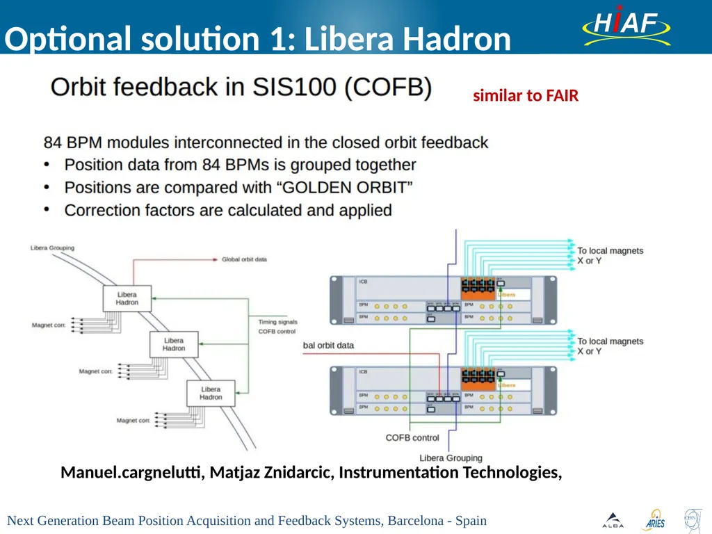
Optional solution 1: Libera Hadron Manuel.cargnelutti, Matjaz Znidarcic, Instrumentation Technologies, similar to FAIR<br>
23
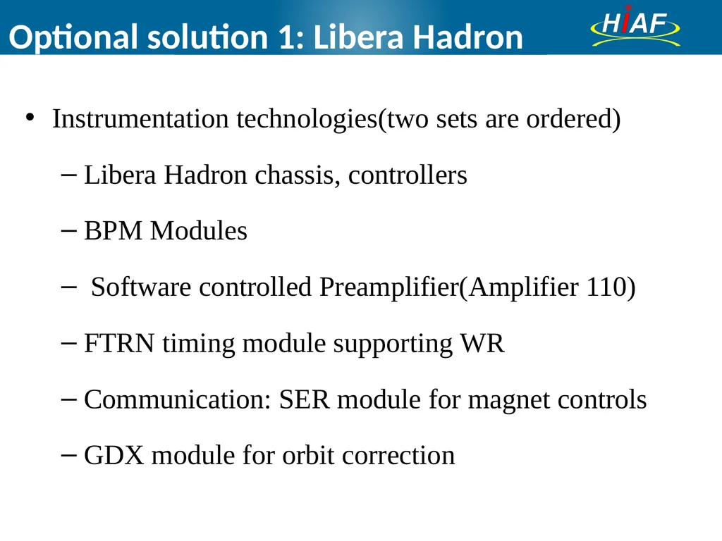
Optional solution 1: Libera Hadron Instrumentation technologies(two sets are ordered)
Libera Hadron chassis, controllers
BPM Modules
Software controlled Preamplifier(Amplifier 110)
FTRN timing module supporting WR
Communication: SER module for magnet controls
GDX module for orbit correction<br>
Libera Hadron chassis, controllers
BPM Modules
Software controlled Preamplifier(Amplifier 110)
FTRN timing module supporting WR
Communication: SER module for magnet controls
GDX module for orbit correction<br>
24
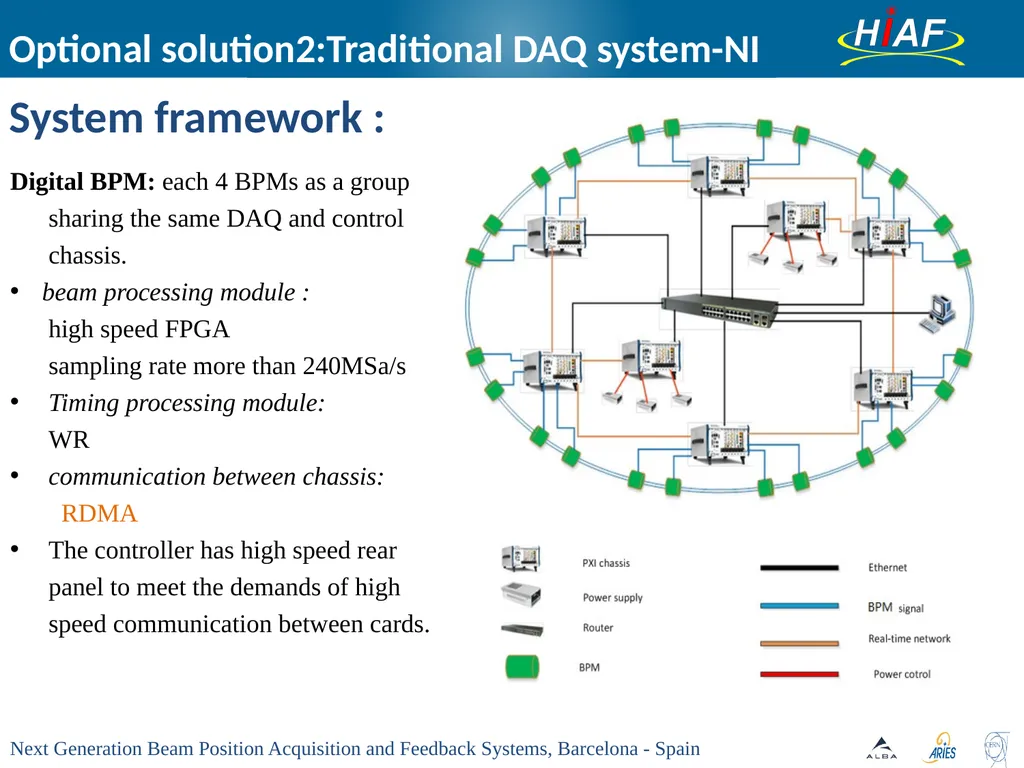
System framework : Optional solution2:Traditional DAQ system-NI Digital BPM: each 4 BPMs as a group sharing the same DAQ and control chassis.
beam processing module :
high speed FPGA
sampling rate more than 240MSa/s
Timing processing module:
WR
communication between chassis:
RDMA
The controller has high speed rear panel to meet the demands of high speed communication between cards.<br>
beam processing module :
high speed FPGA
sampling rate more than 240MSa/s
Timing processing module:
WR
communication between chassis:
RDMA
The controller has high speed rear panel to meet the demands of high speed communication between cards.<br>
25
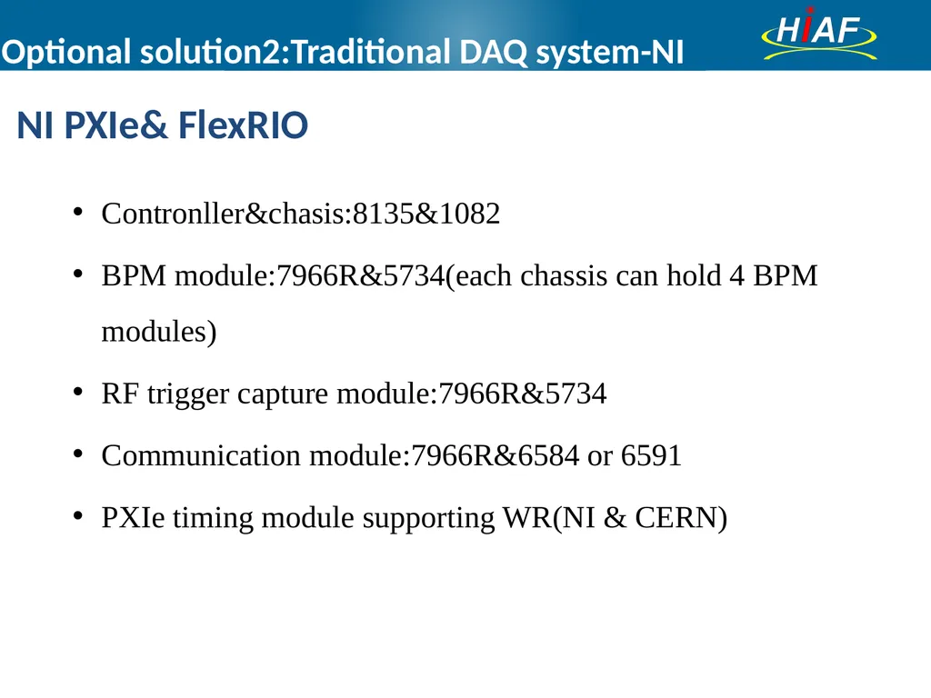
Optional solution2:Traditional DAQ system-NI NI PXIe& FlexRIO Contronller&chasis:8135&1082
BPM module:7966R&5734(each chassis can hold 4 BPM modules)
RF trigger capture module:7966R&5734
Communication module:7966R&6584 or 6591
PXIe timing module supporting WR(NI & CERN)<br>
BPM module:7966R&5734(each chassis can hold 4 BPM modules)
RF trigger capture module:7966R&5734
Communication module:7966R&6584 or 6591
PXIe timing module supporting WR(NI & CERN)<br>
26
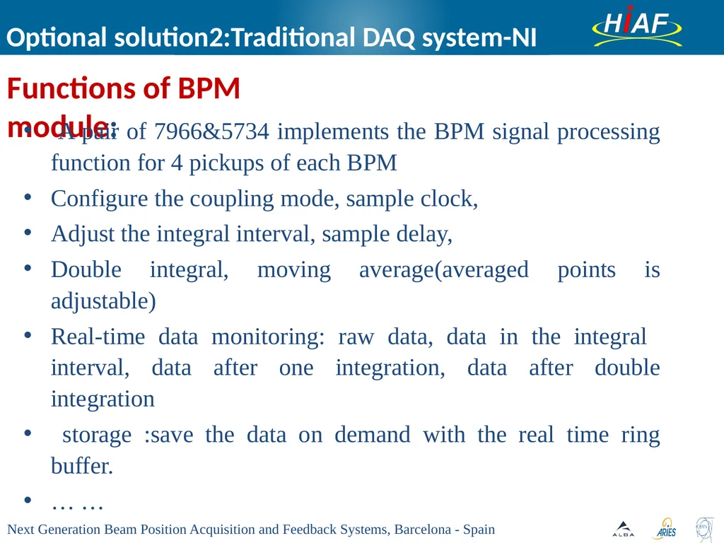
Functions of BPM module: Optional solution2:Traditional DAQ system-NI A pair of 7966&5734 implements the BPM signal processing function for 4 pickups of each BPM
Configure the coupling mode, sample clock,
Adjust the integral interval, sample delay,
Double integral, moving average(averaged points is adjustable)
Real-time data monitoring: raw data, data in the integral interval, data after one integration, data after double integration
storage :save the data on demand with the real time ring buffer.
… …<br>
Configure the coupling mode, sample clock,
Adjust the integral interval, sample delay,
Double integral, moving average(averaged points is adjustable)
Real-time data monitoring: raw data, data in the integral interval, data after one integration, data after double integration
storage :save the data on demand with the real time ring buffer.
… …<br>
27
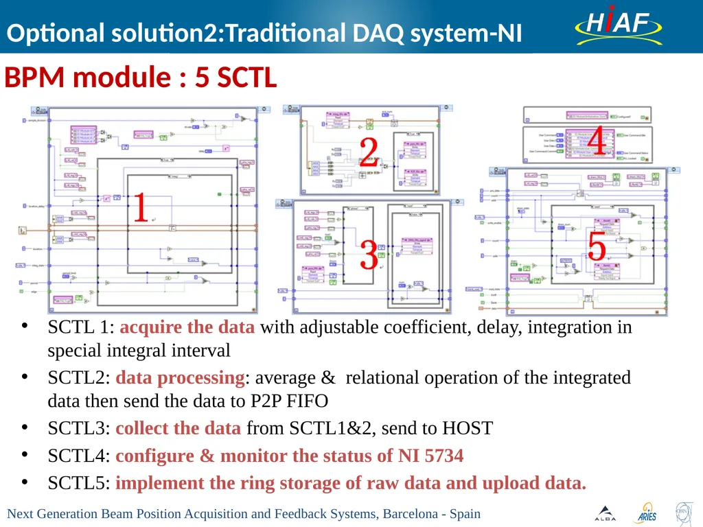
Optional solution2:Traditional DAQ system-NI SCTL 1: acquire the data with adjustable coefficient, delay, integration in special integral interval
SCTL2: data processing: average & relational operation of the integrated data then send the data to P2P FIFO
SCTL3: collect the data from SCTL1&2, send to HOST
SCTL4: configure & monitor the status of NI 5734
SCTL5: implement the ring storage of raw data and upload data. BPM module : 5 SCTL<br>
SCTL2: data processing: average & relational operation of the integrated data then send the data to P2P FIFO
SCTL3: collect the data from SCTL1&2, send to HOST
SCTL4: configure & monitor the status of NI 5734
SCTL5: implement the ring storage of raw data and upload data. BPM module : 5 SCTL<br>
28
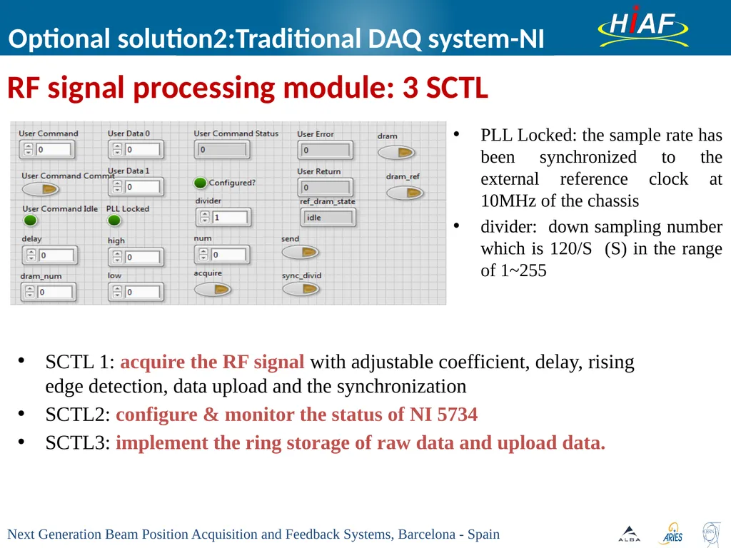
Optional solution2:Traditional DAQ system-NI SCTL 1: acquire the RF signal with adjustable coefficient, delay, rising edge detection, data upload and the synchronization
SCTL2: configure & monitor the status of NI 5734
SCTL3: implement the ring storage of raw data and upload data. RF signal processing module: 3 SCTL PLL Locked: the sample rate has been synchronized to the external reference clock at 10MHz of the chassis
divider: down sampling number which is 120/S (S) in the range of 1~255<br>
SCTL2: configure & monitor the status of NI 5734
SCTL3: implement the ring storage of raw data and upload data. RF signal processing module: 3 SCTL PLL Locked: the sample rate has been synchronized to the external reference clock at 10MHz of the chassis
divider: down sampling number which is 120/S (S) in the range of 1~255<br>
29
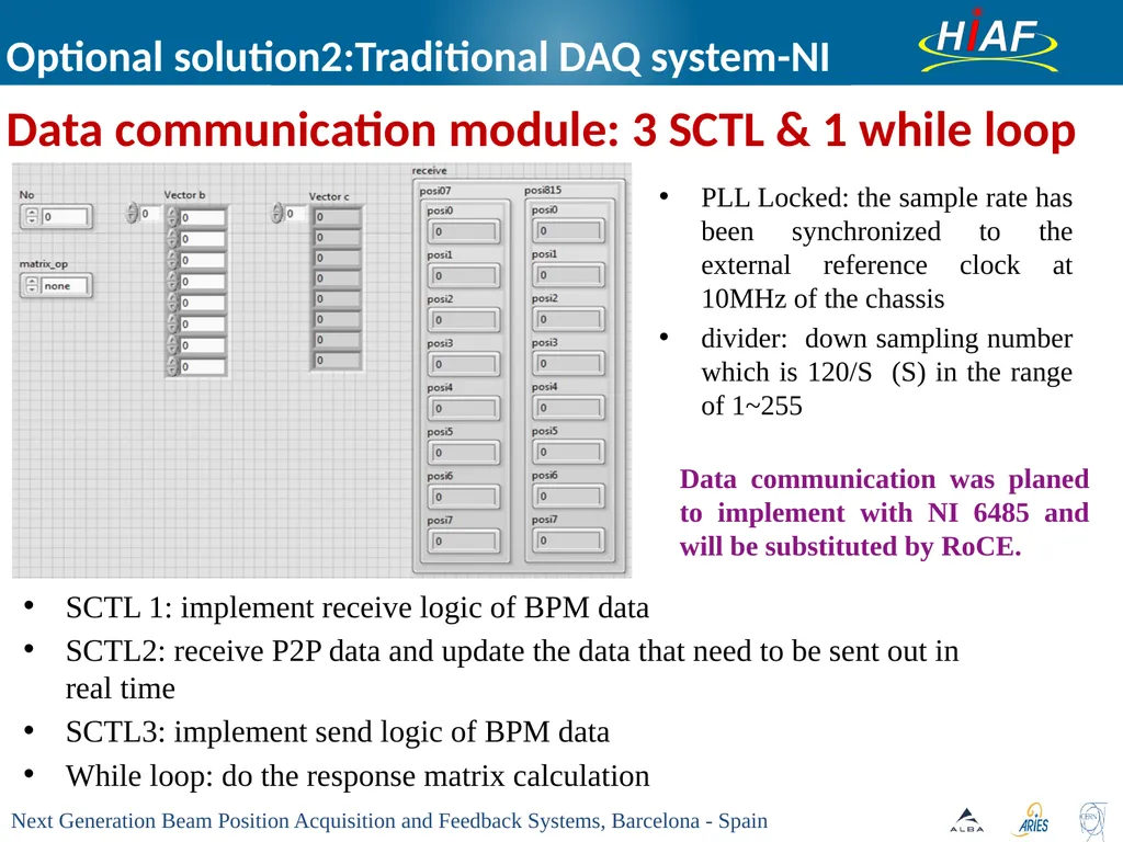
Optional solution2:Traditional DAQ system-NI SCTL 1: implement receive logic of BPM data
SCTL2: receive P2P data and update the data that need to be sent out in real time
SCTL3: implement send logic of BPM data
While loop: do the response matrix calculation Data communication module: 3 SCTL & 1 while loop PLL Locked: the sample rate has been synchronized to the external reference clock at 10MHz of the chassis
divider: down sampling number which is 120/S (S) in the range of 1~255 Data communication was planed to implement with NI 6485 and will be substituted by RoCE.<br>
SCTL2: receive P2P data and update the data that need to be sent out in real time
SCTL3: implement send logic of BPM data
While loop: do the response matrix calculation Data communication module: 3 SCTL & 1 while loop PLL Locked: the sample rate has been synchronized to the external reference clock at 10MHz of the chassis
divider: down sampling number which is 120/S (S) in the range of 1~255 Data communication was planed to implement with NI 6485 and will be substituted by RoCE.<br>
30
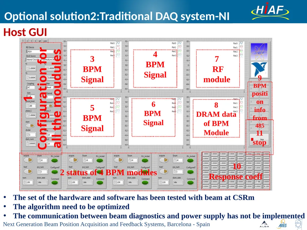
Optional solution2:Traditional DAQ system-NI The set of the hardware and software has been tested with beam at CSRm
The algorithm need to be optimized
The communication between beam diagnostics and power supply has not be implemented Host GUI<br>
The algorithm need to be optimized
The communication between beam diagnostics and power supply has not be implemented Host GUI<br>
31
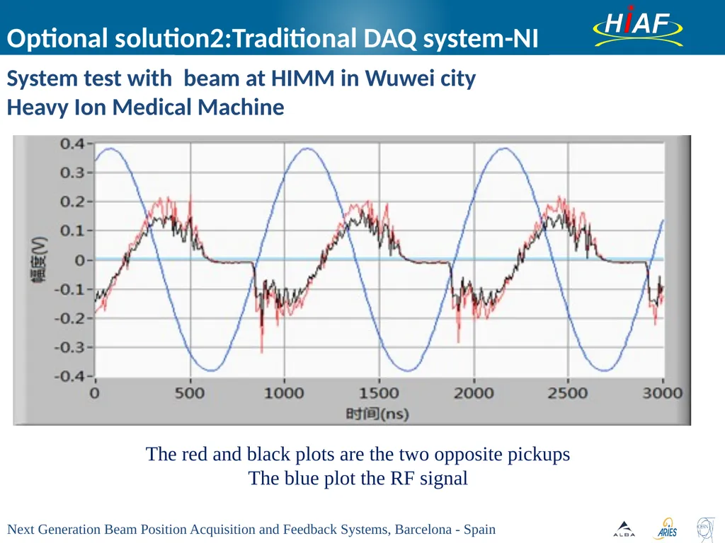
System test with beam at HIMM in Wuwei city
Heavy Ion Medical Machine The red and black plots are the two opposite pickups
The blue plot the RF signal Optional solution2:Traditional DAQ system-NI<br>
Heavy Ion Medical Machine The red and black plots are the two opposite pickups
The blue plot the RF signal Optional solution2:Traditional DAQ system-NI<br>
32
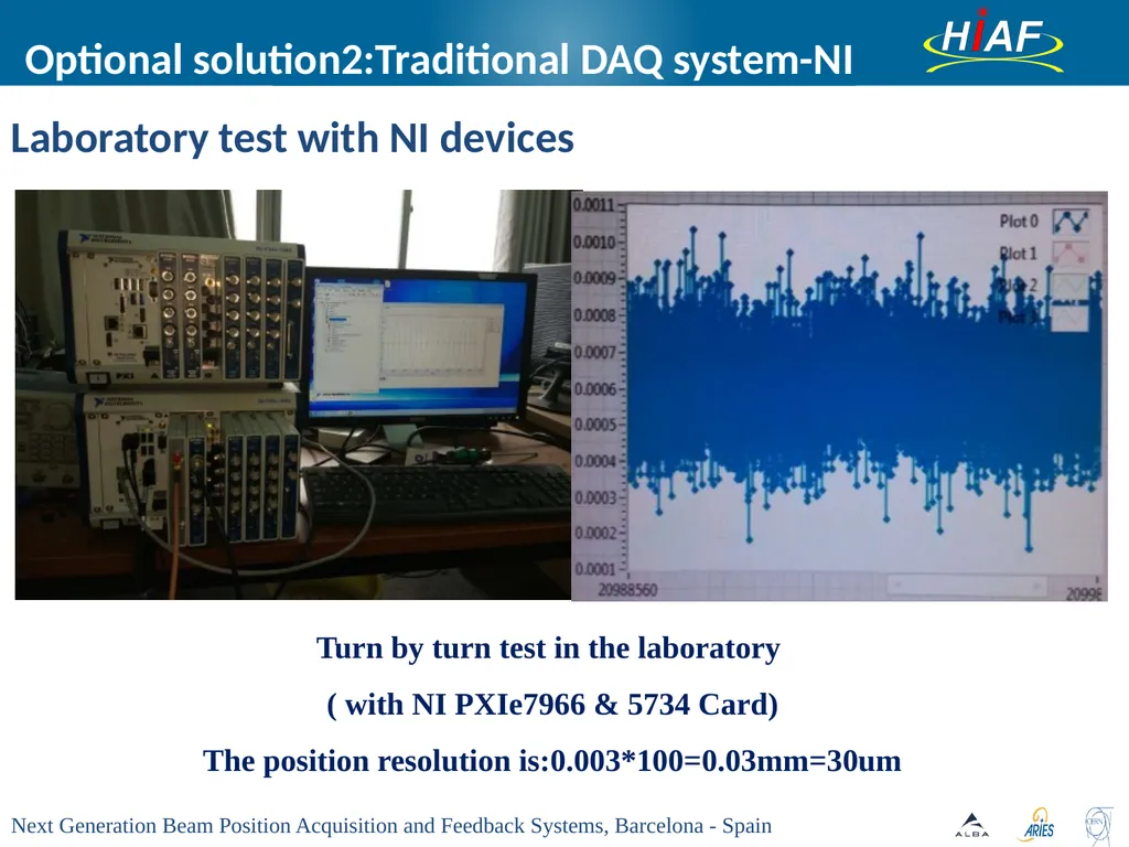
Turn by turn test in the laboratory
( with NI PXIe7966 & 5734 Card)
The position resolution is:0.003*100=0.03mm=30um Optional solution2:Traditional DAQ system-NI Laboratory test with NI devices<br>
( with NI PXIe7966 & 5734 Card)
The position resolution is:0.003*100=0.03mm=30um Optional solution2:Traditional DAQ system-NI Laboratory test with NI devices<br>
33
Outlines HIAF accelerator system
Layout of HIAF
Parameters of COFB at HIAF
Requirements of COFB at HIAF
Key technologies of COFB
Data communication between BPM systems
Data processing algorithm
Candidate COFB design at HIAF
Optional solution 1: Libera Hadron
Optional solution 2: Traditional DAQ system(mainly represented by NI)
Summary<br>
Layout of HIAF
Parameters of COFB at HIAF
Requirements of COFB at HIAF
Key technologies of COFB
Data communication between BPM systems
Data processing algorithm
Candidate COFB design at HIAF
Optional solution 1: Libera Hadron
Optional solution 2: Traditional DAQ system(mainly represented by NI)
Summary<br>
34
Summary Design scheme
The alternative solution of COFB For HIAF is between Libera Hadron and the traditional commercial DAQ system( NI or MicroTCA)
A promising alternative maybe the physics-driven standard MicroTCA.4 because of its high flexibility and modularity, redundant key components, agnostic backplane and advanced management. The Rapid I/O is the preferred choice for the backplane communication.
We may use the RDMA over Converged Ethernet (RoCEV2, FPGA IP Core) with normal Ethernet infrastructure as the low-latency network for the data communication of COFB for HIAF
Data processing algorithm
Simulation of Least-Square Fit Approach(GSI) is the determined at present and the more suitable algorithm will be designed and simulated. Foreseen<br>
The alternative solution of COFB For HIAF is between Libera Hadron and the traditional commercial DAQ system( NI or MicroTCA)
A promising alternative maybe the physics-driven standard MicroTCA.4 because of its high flexibility and modularity, redundant key components, agnostic backplane and advanced management. The Rapid I/O is the preferred choice for the backplane communication.
We may use the RDMA over Converged Ethernet (RoCEV2, FPGA IP Core) with normal Ethernet infrastructure as the low-latency network for the data communication of COFB for HIAF
Data processing algorithm
Simulation of Least-Square Fit Approach(GSI) is the determined at present and the more suitable algorithm will be designed and simulated. Foreseen<br>
35
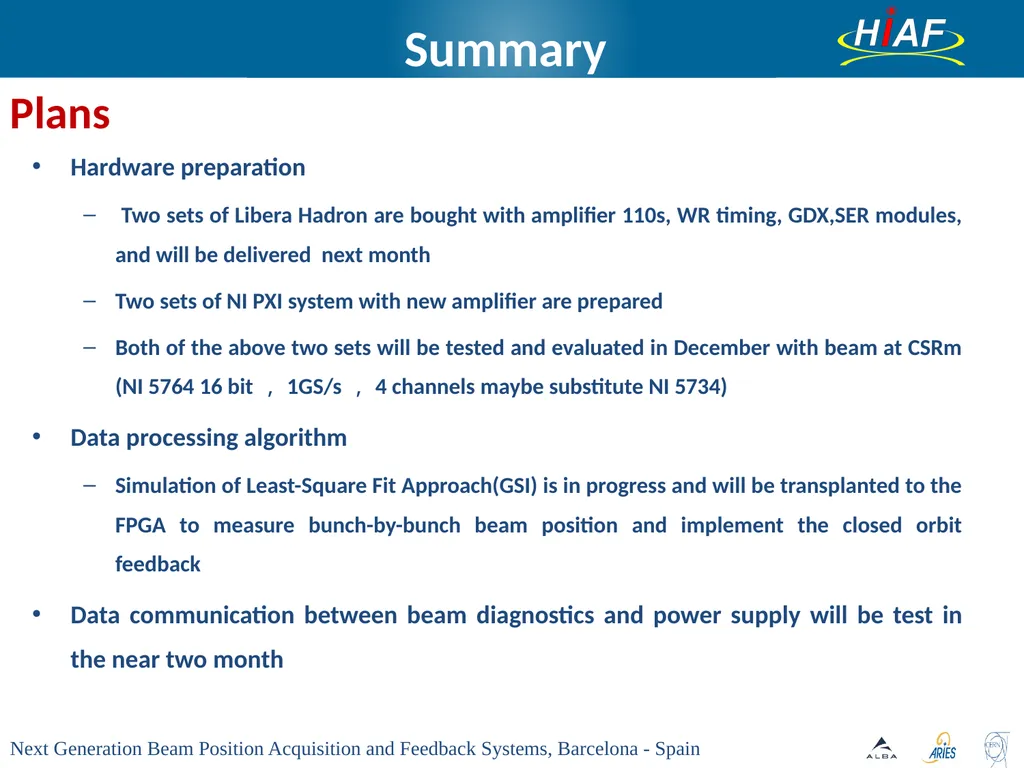
Summary Hardware preparation
Two sets of Libera Hadron are bought with amplifier 110s, WR timing, GDX,SER modules, and will be delivered next month
Two sets of NI PXI system with new amplifier are prepared
Both of the above two sets will be tested and evaluated in December with beam at CSRm (NI 5764 16 bit,1GS/s,4 channels maybe substitute NI 5734)
Data processing algorithm
Simulation of Least-Square Fit Approach(GSI) is in progress and will be transplanted to the FPGA to measure bunch-by-bunch beam position and implement the closed orbit feedback
Data communication between beam diagnostics and power supply will be test in the near two month Plans<br>
Two sets of Libera Hadron are bought with amplifier 110s, WR timing, GDX,SER modules, and will be delivered next month
Two sets of NI PXI system with new amplifier are prepared
Both of the above two sets will be tested and evaluated in December with beam at CSRm (NI 5764 16 bit,1GS/s,4 channels maybe substitute NI 5734)
Data processing algorithm
Simulation of Least-Square Fit Approach(GSI) is in progress and will be transplanted to the FPGA to measure bunch-by-bunch beam position and implement the closed orbit feedback
Data communication between beam diagnostics and power supply will be test in the near two month Plans<br>
36
Thanks for your attention<br>