"Thermo-mechanical Analysis of a Prototypical SiC" is the property of its rightful owner. Permission is granted to
download and print the materials on this website for personal, non-commercial use only, and to display it
on your personal computer provided you do not modify the materials and that you retain all copyright
notices contained in the materials. By downloading content from our website, you accept the terms of this
agreement.
Presentation Transcript
01
Thermo-mechanical Analysis of a Prototypical SiC Foam-Based Flow Channel Insert FNST MEEETING AGENDA
August 18-20, 2009
Rice Room 6764
Boelter Hall, UCLA brian.willimas.@ultramet.com shahrams@ucla.edu<br>
02
Introduction Prototypes of FCI structures using “porous” CVD-SiC foam were fabricated
Mechanical, thermal, and electrical properties of SiC-foam core FCI materials are briefly reviewed
Thermo-mechanical performance tests and analysis of an FCI prototype were performed and will be presented<br>
03
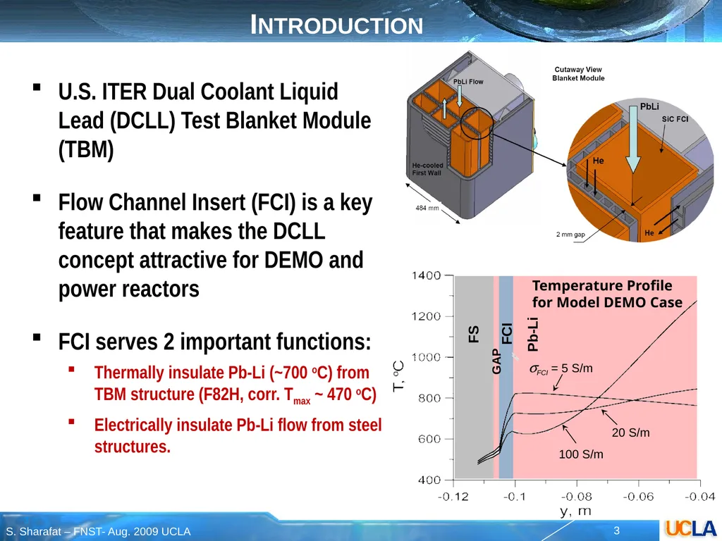
Introduction U.S. ITER Dual Coolant Liquid Lead (DCLL) Test Blanket Module (TBM)
Flow Channel Insert (FCI) is a key feature that makes the DCLL concept attractive for DEMO and power reactors
FCI serves 2 important functions:
Thermally insulate Pb-Li (~700 oC) from TBM structure (F82H, corr. Tmax ~ 470 oC)
Electrically insulate Pb-Li flow from steel structures.<br>
04
FCI Key Requirements Minimize Impact on Tritium Breeding
Adequate thermal insulation
Kth = 2~5 W/m-K for US DCLL TBM
Adequate electrical insulation
sel = 5~100 S/m for US DCLL TBM
Compatibility with Pb-Li
Up to 470ºC for US DCLL TBM, >700ºC for DEMO
In a flow system with large temperature gradients
Leak Tight for Liquid Metal / disconnected porosity
Pb-Li must not “soak” into cracks or pores, must remain isolated in small pores even if cracked
Mechanical integrity
Primary and secondary stresses must not endanger integrity of FCI
Retain Requirements 1 – 5 during operation
Neutron irradiation in D-T phase ITER, and extended to DEMO
Developing flow conditions, temperature & field gradients
Repeated mechanical loading under VDE and disruption events<br>
05
FCI Material Choice Silicon Carbide (SiC) materials fulfill primary operational requirements of Flow Channel Inserts (FCIs)
A number of SiC-based FCI concepts are under development:
SiC/SiC Composites
CVI-SiC Closed Cell Syntactic Foam
CVI-SiC Open Cell Foam Core
Here we discuss Open Cell SiC-Foam Core FCI Prototypes, which were recently heat tested.
Thermo-mechanical performance tests of this FCI prototype will be discussed<br>
06
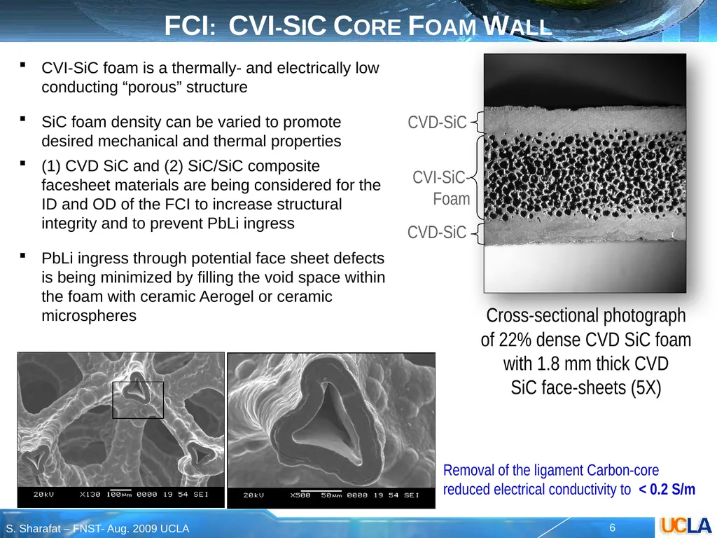
FCI: CVI-SiC Core Foam Wall CVI-SiC foam is a thermally- and electrically low conducting “porous” structure
SiC foam density can be varied to promote desired mechanical and thermal properties
(1) CVD SiC and (2) SiC/SiC composite facesheet materials are being considered for the ID and OD of the FCI to increase structural integrity and to prevent PbLi ingress
PbLi ingress through potential face sheet defects is being minimized by filling the void space within the foam with ceramic Aerogel or ceramic microspheres Cross-sectional photograph of 22% dense CVD SiC foam with 1.8 mm thick CVD SiC face-sheets (5X) Removal of the ligament Carbon-core reduced electrical conductivity to < 0.2 S/m CVI-SiC-Foam CVD-SiC CVD-SiC<br>
07
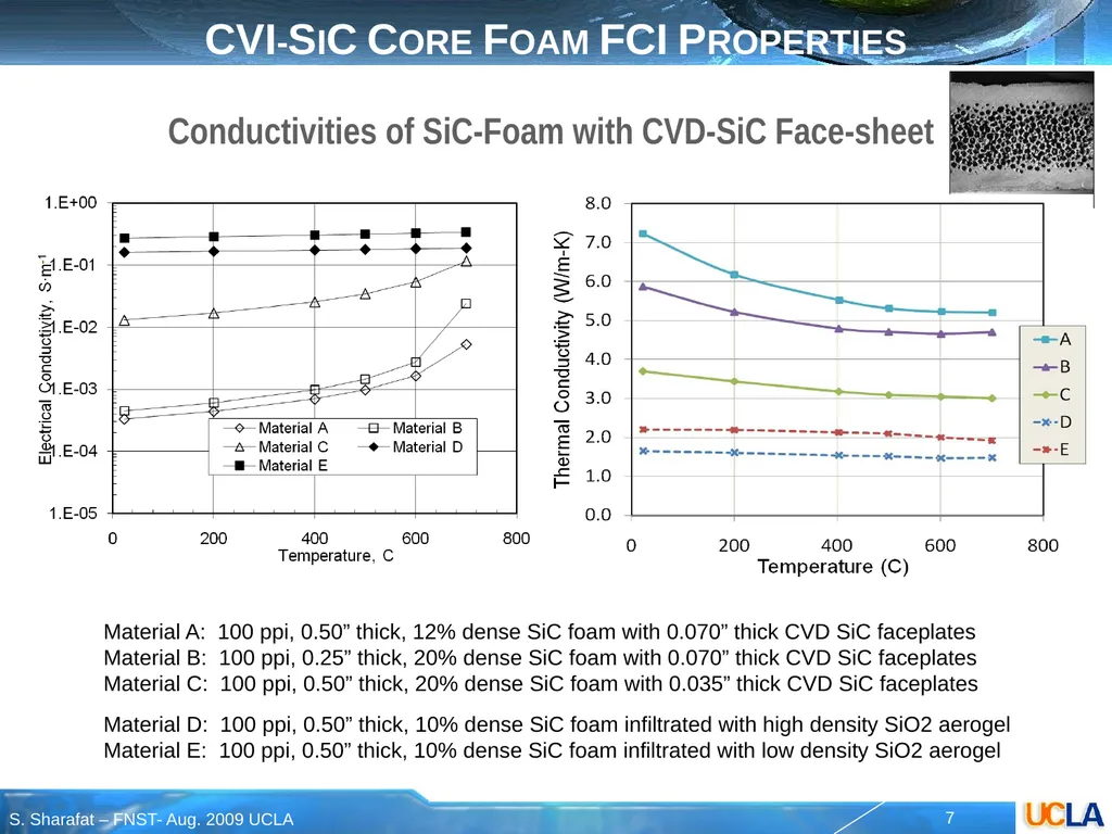
Conductivities of SiC-Foam with CVD-SiC Face-sheet Material A: 100 ppi, 0.50” thick, 12% dense SiC foam with 0.070” thick CVD SiC faceplates
Material B: 100 ppi, 0.25” thick, 20% dense SiC foam with 0.070” thick CVD SiC faceplates
Material C: 100 ppi, 0.50” thick, 20% dense SiC foam with 0.035” thick CVD SiC faceplates
Material D: 100 ppi, 0.50” thick, 10% dense SiC foam infiltrated with high density SiO2 aerogel
Material E: 100 ppi, 0.50” thick, 10% dense SiC foam infiltrated with low density SiO2 aerogel CVI-SiC Core Foam FCI Properties<br>
08
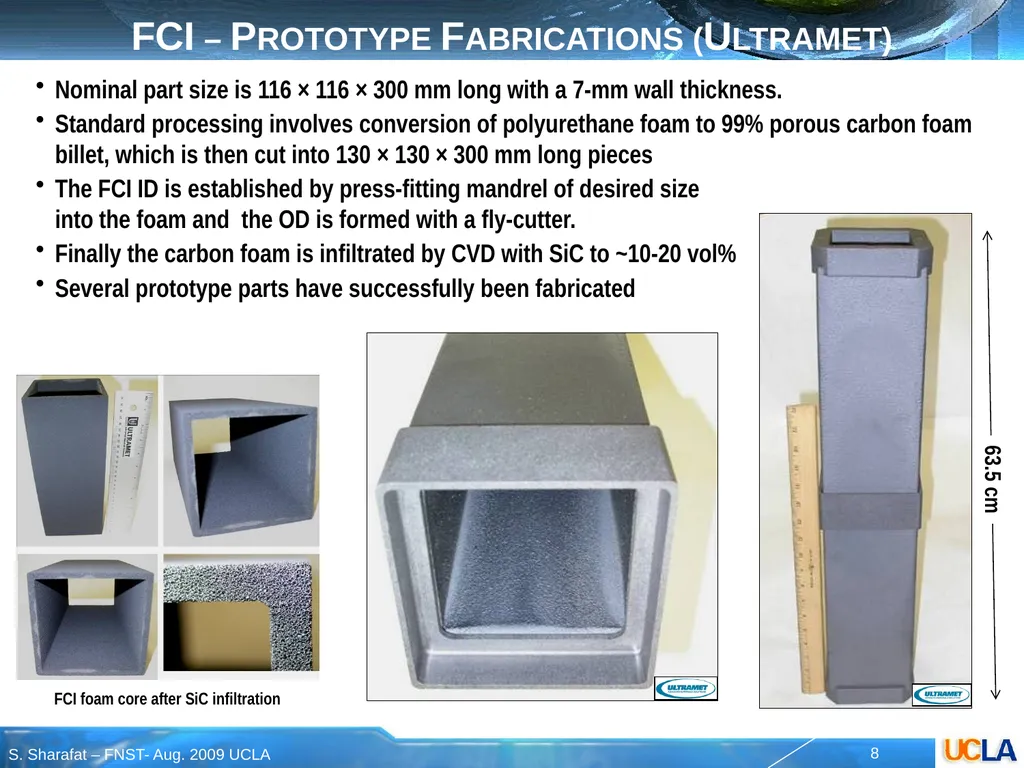
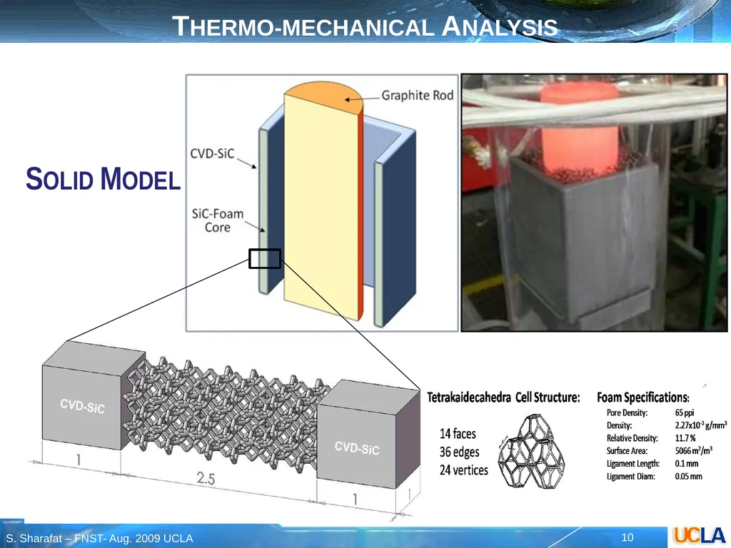
FCI – Prototype Fabrications (Ultramet) Nominal part size is 116 × 116 × 300 mm long with a 7-mm wall thickness.
Standard processing involves conversion of polyurethane foam to 99% porous carbon foam billet, which is then cut into 130 × 130 × 300 mm long pieces
The FCI ID is established by press-fitting mandrel of desired size into the foam and the OD is formed with a fly-cutter.
Finally the carbon foam is infiltrated by CVD with SiC to ~10-20 vol%
Several prototype parts have successfully been fabricated FCI foam core after SiC infiltration<br>
09
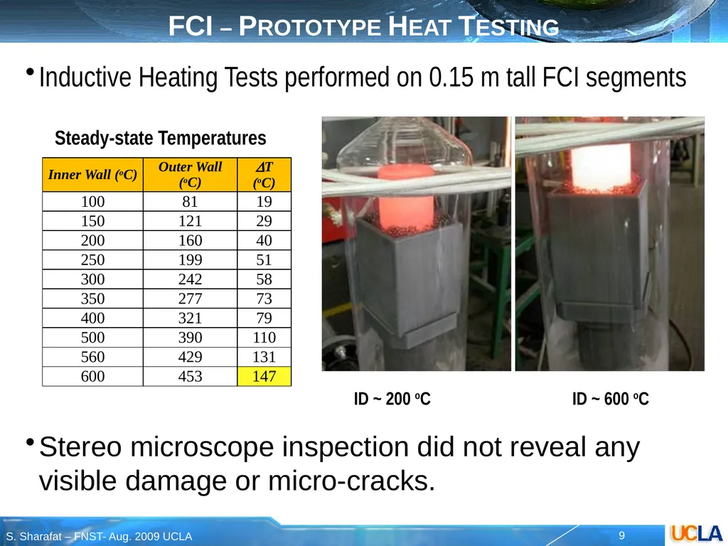
FCI – Prototype Heat Testing Inductive Heating Tests performed on 0.15 m tall FCI segments ID ~ 200 oC ID ~ 600 oC Steady-state Temperatures Stereo microscope inspection did not reveal any visible damage or micro-cracks.<br>
10
Thermo-mechanical Analysis Solid Model<br>
11
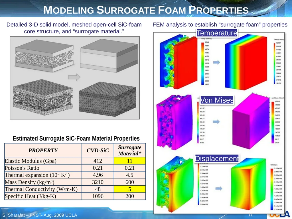
Modeling Surrogate Foam Properties Detailed 3-D solid model, meshed open-cell SiC-foam core structure, and “surrogate material.” Temperature Von Mises Displacement FEM analysis to establish “surrogate foam” properties Estimated Surrogate SiC-Foam Material Properties<br>
12
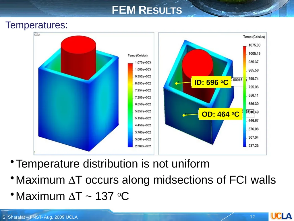
FEM Results Temperatures: Temperature distribution is not uniform
Maximum DT occurs along midsections of FCI walls
Maximum DT ~ 137 oC ID: 596 oC OD: 464 oC<br>
13
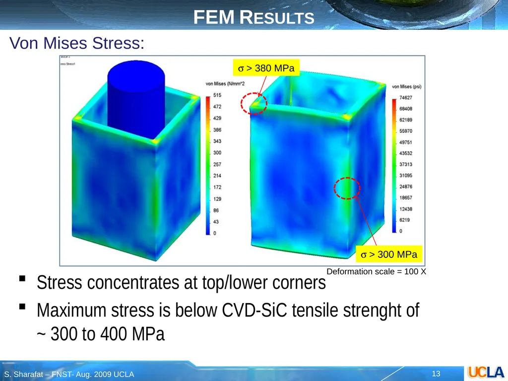
FEM Results Von Mises Stress: Stress concentrates at top/lower corners
Maximum stress is below CVD-SiC tensile strenght of ~ 300 to 400 MPa s > 380 MPa s > 300 MPa Deformation scale = 100 X<br>
14
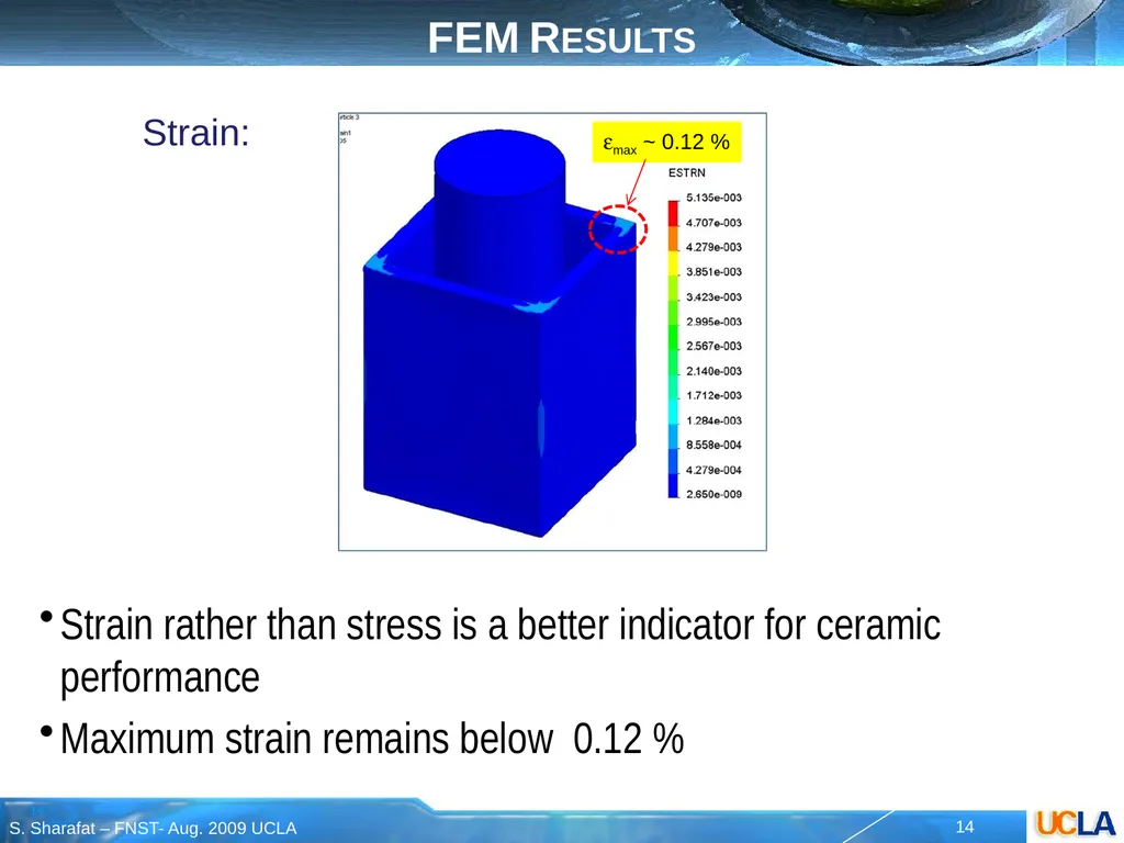
FEM Results Strain: Strain rather than stress is a better indicator for ceramic performance
Maximum strain remains below 0.12 % emax ~ 0.12 %<br>
15
FEM Result Discussions FCI heating tests (Dt ~ 147 oC) showed no visibly discernable sign of damage (microscopic analysis was not performed)
Conservative thermo-mechanical analysis estimates stresses to be below CVD-SiC tensile strength, even though:
FEM analysis assumes sharp interface between CVD-SiC face sheet and SiC-foam no gradual transition between CVD-SiC face sheet and SiC-foam
Mechanical properties of surrogate material for SiC foam may be underestimated (E ~ 11 GPa)
The outer 1-mm thick CVD-SiC shell carries the load<br>
16
Conclusions Several FCI prototypes structure were fabricated
The FCI wall structure consists of CVI-SiC foam core (~5 mm) between CVD-SiC face sheets (~1 mm)
Heat tests up to DT~150 oC did not result in visibly discernable damage (no microscopical analysis)
Thermo-mechanical analysis of the heat test estimates maximum stresses to be below CVD-SiC tensile strength
The heat tested performance of the FCI prototype implies that the open-cell foam core based FCI structure holds promise for TBM.<br>
17
shahrams@ucla.edu brian.williams@ultramet.com Thank you for your attention<br>
18
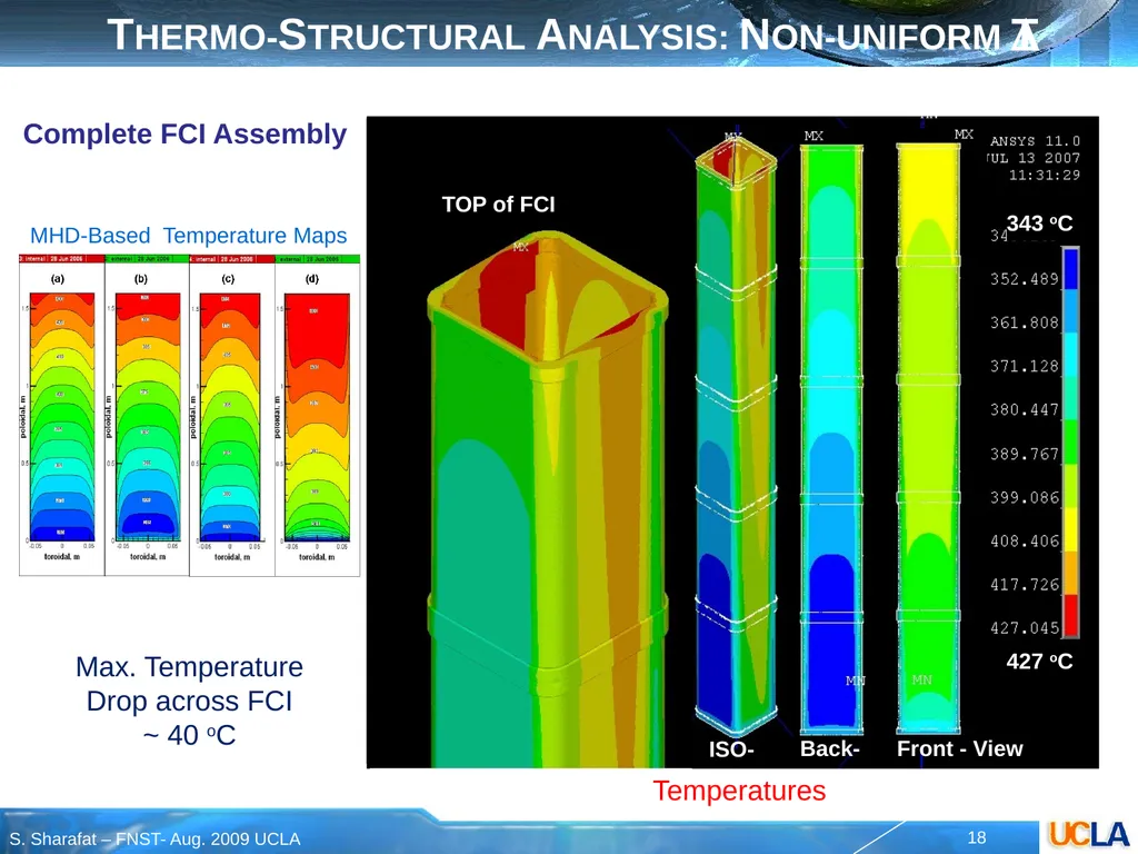
Thermo-Structural Analysis: Non-uniform DT MHD-Based Temperature Maps Max. Temperature
Drop across FCI ~ 40 oC Temperatures Complete FCI Assembly<br>
19
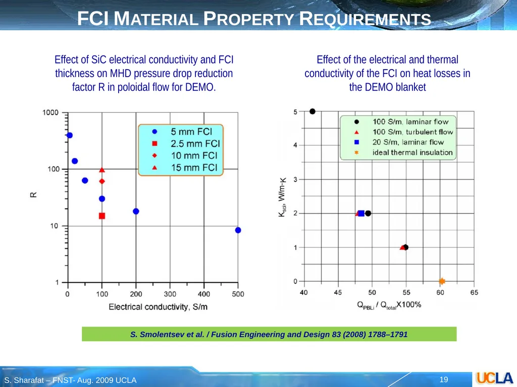
FCI Material Property Requirements Effect of the electrical and thermal conductivity of the FCI on heat losses in the DEMO blanket S. Smolentsev et al. / Fusion Engineering and Design 83 (2008) 1788–1791 Effect of SiC electrical conductivity and FCI thickness on MHD pressure drop reduction factor R in poloidal flow for DEMO.<br>
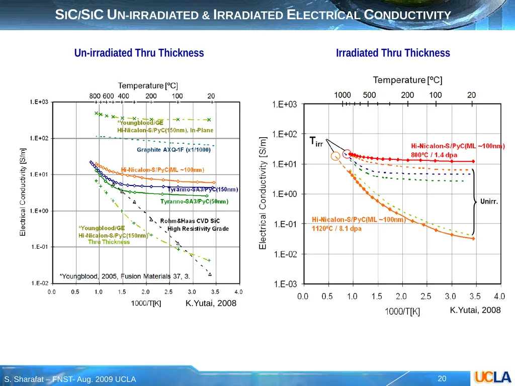
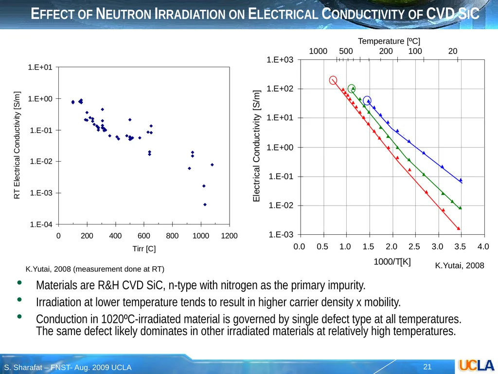
Tirr Effect of Neutron Irradiation on Electrical Conductivity of CVD SiC Materials are R&H CVD SiC, n-type with nitrogen as the primary impurity.
Irradiation at lower temperature tends to result in higher carrier density x mobility.
Conduction in 1020ºC-irradiated material is governed by single defect type at all temperatures. The same defect likely dominates in other irradiated materials at relatively high temperatures. ~375 meV K.Yutai, 2008 (measurement done at RT) K.Yutai, 2008<br>