
UNIT 2 Chapter 2 Transmission media Department of
TD
Published · 34 slides · 0 views

1 / 1

Description
UNIT 2 Chapter 2 Transmission media Department of Information Technology , SIES College of Arts, Science Commerce (Autonomous) Transmission media Department of Information Technology , SIES College of Arts, Science Commerce (Autonomous)
Related Topics
Share
Embed code
Download this presentation From Below
"UNIT 2 Chapter 2 Transmission media Department of" is the property of its rightful owner. Permission is granted to download and print the materials on this website for personal, non-commercial use only, and to display it on your personal computer provided you do not modify the materials and that you retain all copyright notices contained in the materials. By downloading content from our website, you accept the terms of this agreement.
Presentation Transcript
01
UNIT 2 Chapter 2
Transmission media Department of Information Technology , SIES College of Arts, Science & Commerce (Autonomous)<br>
Transmission media Department of Information Technology , SIES College of Arts, Science & Commerce (Autonomous)<br>
02
Transmission media Department of Information Technology , SIES College of Arts, Science & Commerce (Autonomous) Transmission media are actually located below the physical layer and are directly controlled by the physical layer.
A transmission medium can be broadly defined as anything that can carry information
from a source to a destination.
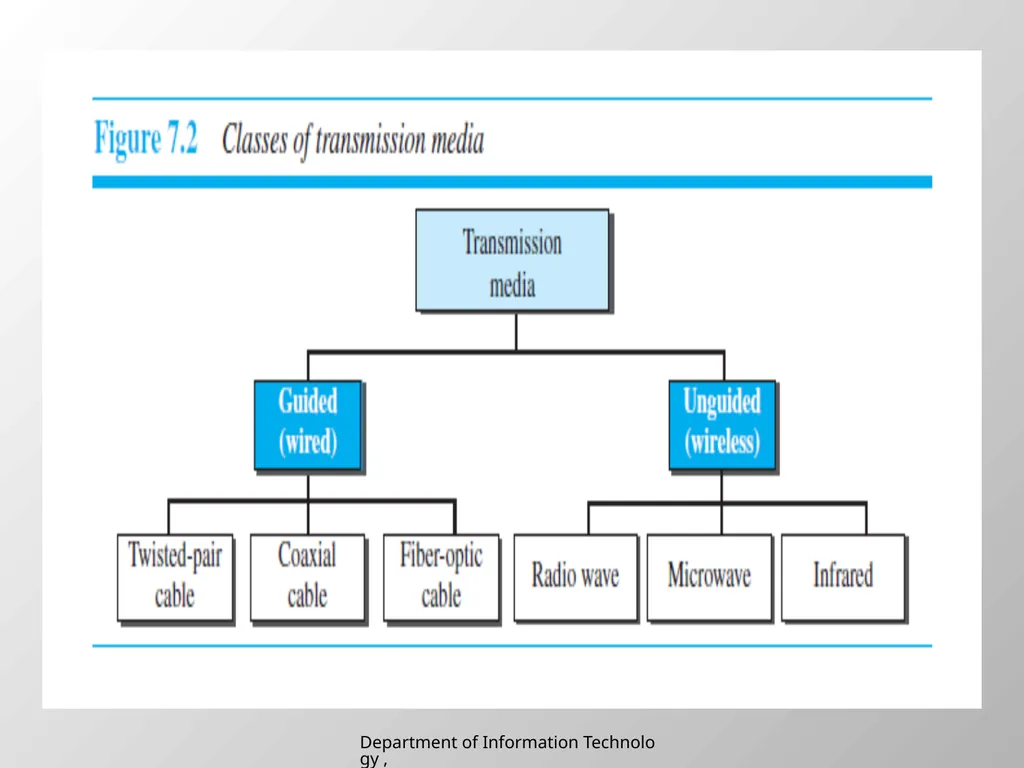
In telecommunications, transmission media can be divided into two broad categories:
guided and unguided. Guided media include twisted-pair cable, coaxial cable, and
fiber-optic cable.<br>
A transmission medium can be broadly defined as anything that can carry information
from a source to a destination.
In telecommunications, transmission media can be divided into two broad categories:
guided and unguided. Guided media include twisted-pair cable, coaxial cable, and
fiber-optic cable.<br>
03
Department of Information Technology , SIES College of Arts, Science & Commerce (Autonomous)<br>
04
GUIDED MEDIA Guided media, which are those that provide a conduit from one device to another, include twisted-pair cable, coaxial cable, and fiber-optic cable.
A signal traveling along any of these media is directed and contained by the physical limits of the medium.
Twisted-pair and coaxial cable use metallic (copper) conductors that accept and transport signals in the form of electric current.
Optical fiber is a cable that accepts and transports signals in the form of light. Department of Information Technology , SIES College of Arts, Science & Commerce (Autonomous)<br>
A signal traveling along any of these media is directed and contained by the physical limits of the medium.
Twisted-pair and coaxial cable use metallic (copper) conductors that accept and transport signals in the form of electric current.
Optical fiber is a cable that accepts and transports signals in the form of light. Department of Information Technology , SIES College of Arts, Science & Commerce (Autonomous)<br>
05
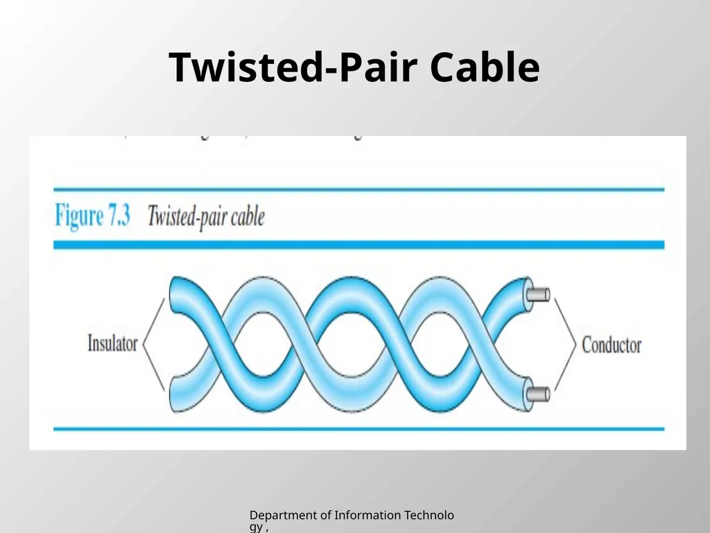
Twisted-Pair Cable Department of Information Technology , SIES College of Arts, Science & Commerce (Autonomous)<br>
06
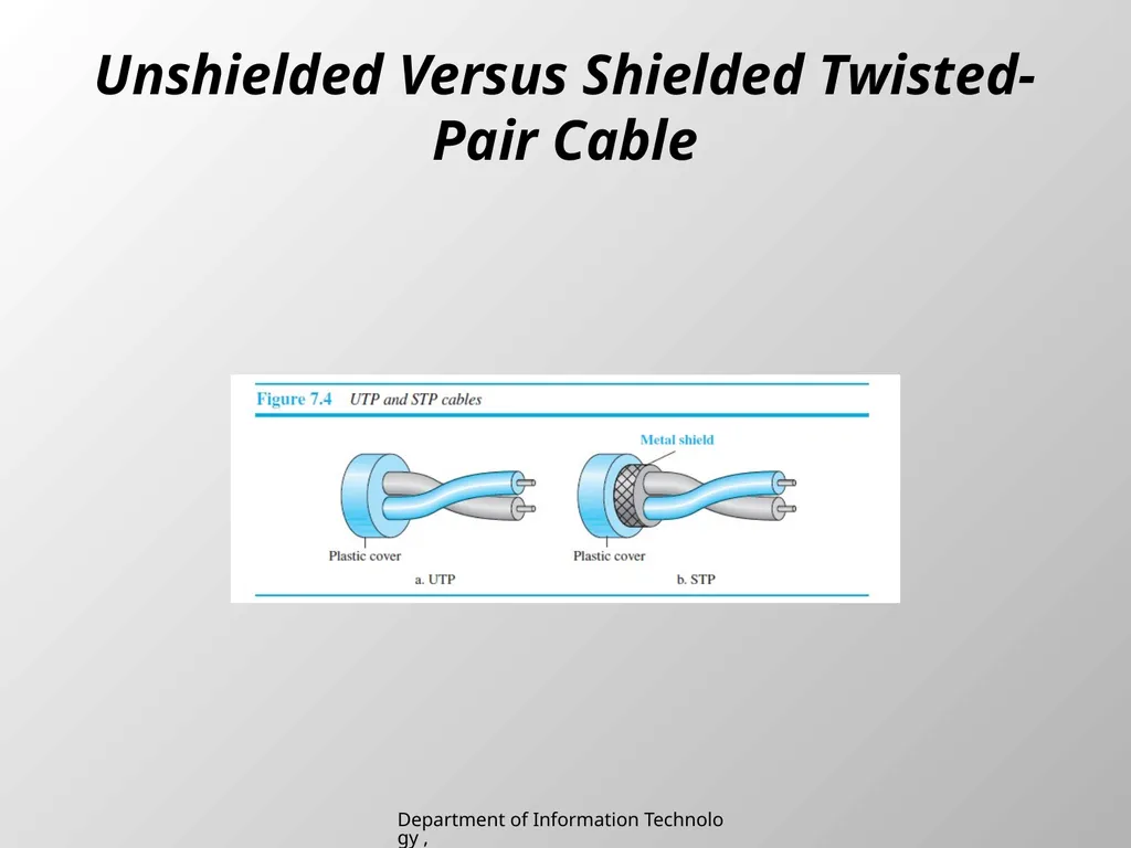
Unshielded Versus Shielded Twisted-Pair Cable Department of Information Technology , SIES College of Arts, Science & Commerce (Autonomous)<br>
07
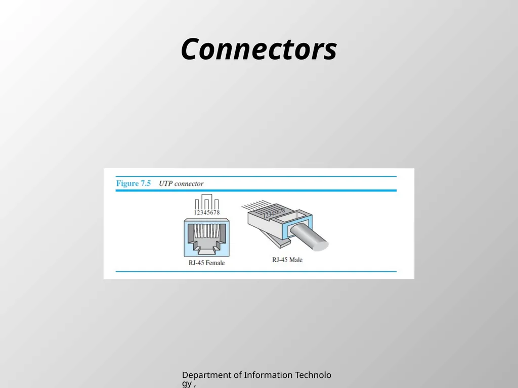
Connectors Department of Information Technology , SIES College of Arts, Science & Commerce (Autonomous)<br>
08
Applications Twisted-pair cables are used in telephone lines to provide voice and data channels.
The local loop—the line that connects subscribers to the central telephone office—commonly consists of unshielded twisted-pair cables.
The DSL lines that are used by the telephone companies to provide high-data-rate connections also use the high-bandwidth capability of unshielded twisted-pair cables. Department of Information Technology , SIES College of Arts, Science & Commerce (Autonomous)<br>
The local loop—the line that connects subscribers to the central telephone office—commonly consists of unshielded twisted-pair cables.
The DSL lines that are used by the telephone companies to provide high-data-rate connections also use the high-bandwidth capability of unshielded twisted-pair cables. Department of Information Technology , SIES College of Arts, Science & Commerce (Autonomous)<br>
09
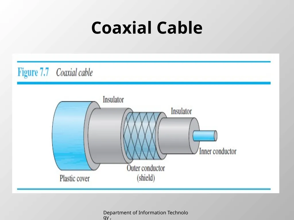
Coaxial Cable Department of Information Technology , SIES College of Arts, Science & Commerce (Autonomous)<br>
10
Coaxial Cable Connectors Department of Information Technology , SIES College of Arts, Science & Commerce (Autonomous)<br>
11
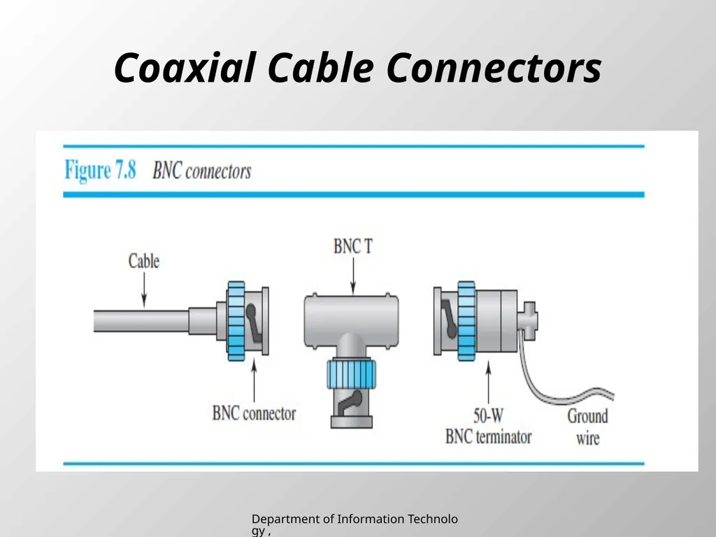
To connect coaxial cable to devices, we need coaxial connectors.
The most common type of connector used today is the Bayonet Neill-Concelman (BNC) connector.
Figure 7.8 shows three popular types of these connectors: the BNC connector, the BNC T connector, and the BNC terminator. Department of Information Technology , SIES College of Arts, Science & Commerce (Autonomous)<br>
The most common type of connector used today is the Bayonet Neill-Concelman (BNC) connector.
Figure 7.8 shows three popular types of these connectors: the BNC connector, the BNC T connector, and the BNC terminator. Department of Information Technology , SIES College of Arts, Science & Commerce (Autonomous)<br>
12
Applications Coaxial cable was widely used in analog telephone networks where a single coaxial network could carry 10,000 voice signals.
Later it was used in digital telephone networks where a single coaxial cable could carry digital data up to 600 Mbps.
Cable TV networks also use coaxial cables.
Another common application of coaxial cable is in traditional Ethernet LANs. Department of Information Technology , SIES College of Arts, Science & Commerce (Autonomous)<br>
Later it was used in digital telephone networks where a single coaxial cable could carry digital data up to 600 Mbps.
Cable TV networks also use coaxial cables.
Another common application of coaxial cable is in traditional Ethernet LANs. Department of Information Technology , SIES College of Arts, Science & Commerce (Autonomous)<br>
13
Fiber-Optic Cable Department of Information Technology , SIES College of Arts, Science & Commerce (Autonomous)<br>
14
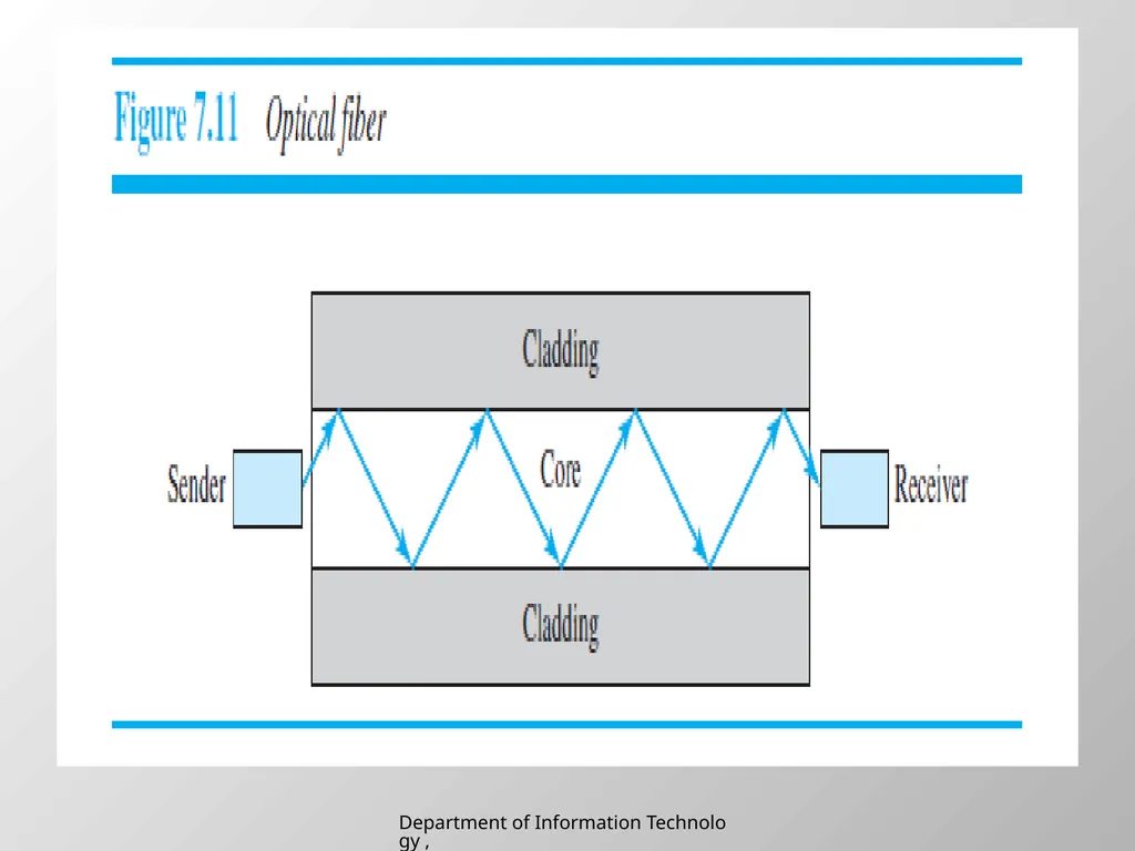
A fiber-optic cable is made of glass or plastic and transmits signals in the form of light.
Light travels in a straight line as long as it is moving through a single uniform substance.
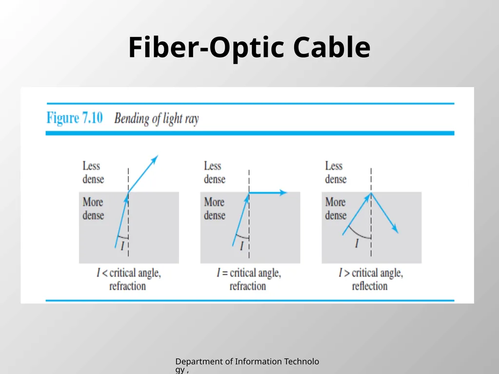
If a ray of light traveling through one substance suddenly enters another substance (of a different density), the ray changes direction. Figure 7.10 shows how a ray of light changes direction when going from a more dense to a less dense substance. Department of Information Technology , SIES College of Arts, Science & Commerce (Autonomous)<br>
Light travels in a straight line as long as it is moving through a single uniform substance.
If a ray of light traveling through one substance suddenly enters another substance (of a different density), the ray changes direction. Figure 7.10 shows how a ray of light changes direction when going from a more dense to a less dense substance. Department of Information Technology , SIES College of Arts, Science & Commerce (Autonomous)<br>
15
Department of Information Technology , SIES College of Arts, Science & Commerce (Autonomous)<br>
16
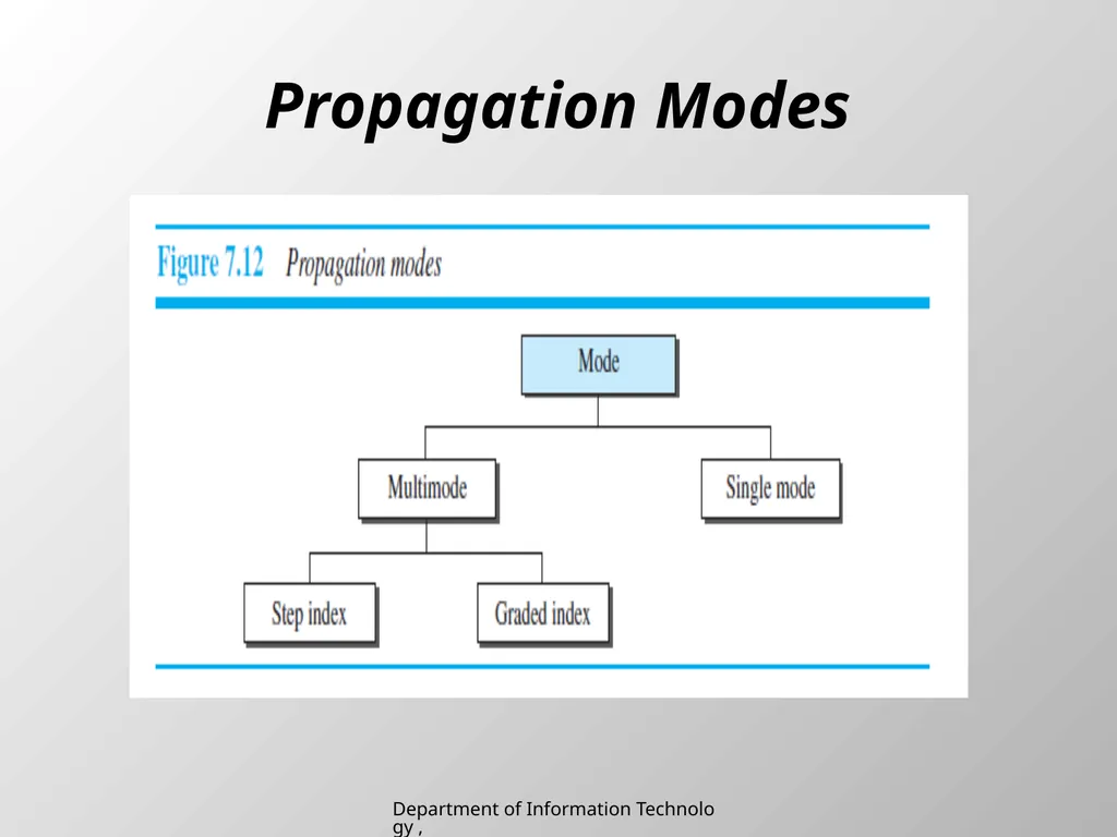
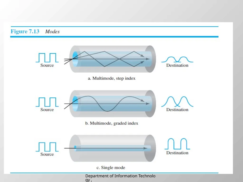
Propagation Modes Department of Information Technology , SIES College of Arts, Science & Commerce (Autonomous)<br>
17
Department of Information Technology , SIES College of Arts, Science & Commerce (Autonomous)<br>
18
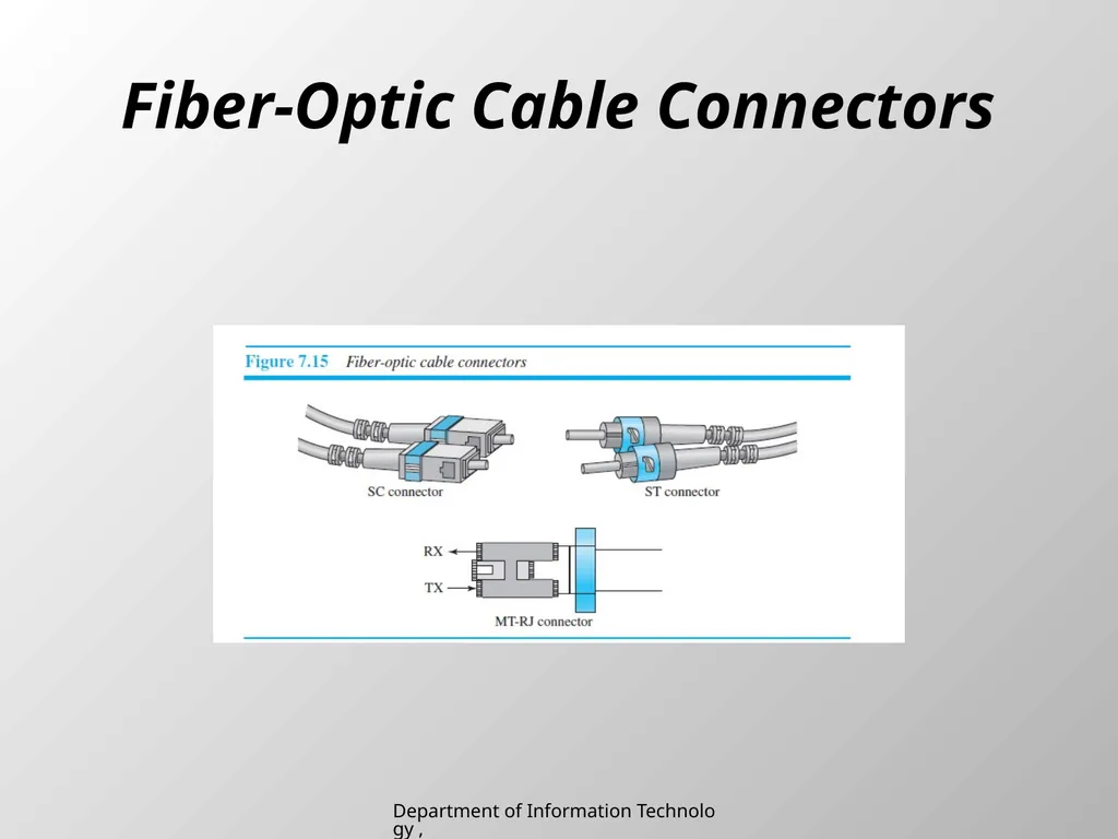
Fiber-Optic Cable Connectors Department of Information Technology , SIES College of Arts, Science & Commerce (Autonomous)<br>
19
Applications Some cable TV companies use a combination of optical fiber and coaxial cable,thus creating a hybrid network.
Local-area networks such as 100Base-FX network (Fast Ethernet) and 1000Base-X also use fiber-optic cable. Department of Information Technology , SIES College of Arts, Science & Commerce (Autonomous)<br>
Local-area networks such as 100Base-FX network (Fast Ethernet) and 1000Base-X also use fiber-optic cable. Department of Information Technology , SIES College of Arts, Science & Commerce (Autonomous)<br>
20
Advantages and Disadvantages of Optical Fiber Advantages
Higher bandwidth. Fiber-optic cable can support dramatically higher bandwidths
Less signal attenuation
Immunity to electromagnetic interference. Electromagnetic noise cannot affect
Resistance to corrosive materials. Glass is more resistant to corrosive materials
Light weight
Greater immunity to tapping. Department of Information Technology , SIES College of Arts, Science & Commerce (Autonomous)<br>
Higher bandwidth. Fiber-optic cable can support dramatically higher bandwidths
Less signal attenuation
Immunity to electromagnetic interference. Electromagnetic noise cannot affect
Resistance to corrosive materials. Glass is more resistant to corrosive materials
Light weight
Greater immunity to tapping. Department of Information Technology , SIES College of Arts, Science & Commerce (Autonomous)<br>
21
Disadvantages
Installation and maintenance.
Unidirectional light propagation.
Cost. Department of Information Technology , SIES College of Arts, Science & Commerce (Autonomous)<br>
Installation and maintenance.
Unidirectional light propagation.
Cost. Department of Information Technology , SIES College of Arts, Science & Commerce (Autonomous)<br>
22
UNGUIDED MEDIA: WIRELESS Unguided medium transport electromagnetic waves without using a physical conductor.
This type of communication is often referred to as wireless communication.
Signals are normally broadcast through free space and thus are available to anyone who has a device capable of receiving them.
Unguided signals can travel from the source to the destination in several ways: ground propagation, sky propagation, and line-of-sight propagation. Department of Information Technology , SIES College of Arts, Science & Commerce (Autonomous)<br>
This type of communication is often referred to as wireless communication.
Signals are normally broadcast through free space and thus are available to anyone who has a device capable of receiving them.
Unguided signals can travel from the source to the destination in several ways: ground propagation, sky propagation, and line-of-sight propagation. Department of Information Technology , SIES College of Arts, Science & Commerce (Autonomous)<br>
23
In ground propagation, radio waves travel through the lowest portion of the atmosphere,hugging the earth.
In sky propagation, higher-frequency radio waves radiate upward into the ionosphere (the layer of atmosphere where particles exist as ions) where they are reflected back to earth. This type of transmission allows for greater distances with lower output power.
In line-of-sight propagation, very high-frequency signals are transmitted in straight lines directly from antenna to antenna. Department of Information Technology , SIES College of Arts, Science & Commerce (Autonomous)<br>
In sky propagation, higher-frequency radio waves radiate upward into the ionosphere (the layer of atmosphere where particles exist as ions) where they are reflected back to earth. This type of transmission allows for greater distances with lower output power.
In line-of-sight propagation, very high-frequency signals are transmitted in straight lines directly from antenna to antenna. Department of Information Technology , SIES College of Arts, Science & Commerce (Autonomous)<br>
24
The section of the electromagnetic spectrum defined as radio waves and microwaves is divided into eight ranges, called bands, each regulated by government authorities.
These bands are rated from very low frequency (VLF) to extremely high frequency (EHF).
We can divide wireless transmission into three broad groups: radio waves, microwaves,and infrared waves. Department of Information Technology , SIES College of Arts, Science & Commerce (Autonomous)<br>
These bands are rated from very low frequency (VLF) to extremely high frequency (EHF).
We can divide wireless transmission into three broad groups: radio waves, microwaves,and infrared waves. Department of Information Technology , SIES College of Arts, Science & Commerce (Autonomous)<br>
25
Radio Waves Electromagnetic waves ranging in frequencies between 3 kHz and 1 GHz are normally called radio waves; waves ranging in frequencies between 1 and 300 GHz are called microwaves.
Radio waves, for the most part, are omnidirectional.
When an antenna transmits radio waves, they are propagated in all directions.
This means that the sending and receiving antennas do not have to be aligned.
A sending antenna sends waves that can be received by any receiving antenna.. Department of Information Technology , SIES College of Arts, Science & Commerce (Autonomous)<br>
Radio waves, for the most part, are omnidirectional.
When an antenna transmits radio waves, they are propagated in all directions.
This means that the sending and receiving antennas do not have to be aligned.
A sending antenna sends waves that can be received by any receiving antenna.. Department of Information Technology , SIES College of Arts, Science & Commerce (Autonomous)<br>
26
The omnidirectional property has a disadvantage,too.
The radio waves transmitted by one antenna are susceptible to interference by another antenna that may send signals using the same frequency or band.
Radio waves, particularly those waves that propagate in the sky mode, can travel long distances.
This makes radio waves a good candidate for long-distance broadcasting such as AM radio. Department of Information Technology , SIES College of Arts, Science & Commerce (Autonomous)<br>
The radio waves transmitted by one antenna are susceptible to interference by another antenna that may send signals using the same frequency or band.
Radio waves, particularly those waves that propagate in the sky mode, can travel long distances.
This makes radio waves a good candidate for long-distance broadcasting such as AM radio. Department of Information Technology , SIES College of Arts, Science & Commerce (Autonomous)<br>
27
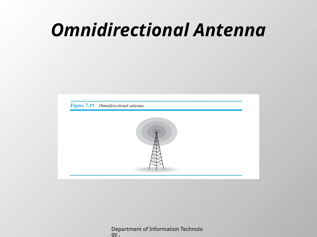
Omnidirectional Antenna Department of Information Technology , SIES College of Arts, Science & Commerce (Autonomous)<br>
28
Applications The omnidirectional characteristics of radio waves make them useful for multicasting,in which there is one sender but many receivers. AM and FM radio, television, maritime radio, cordless phones, and paging are examples of multicasting. Department of Information Technology , SIES College of Arts, Science & Commerce (Autonomous)<br>
29
Microwaves Electromagnetic waves having frequencies between 1 and 300 GHz are called microwaves.
Microwaves are unidirectional.
When an antenna transmits microwaves, they can be narrowly focused.
This means that the sending and receiving antennas need to be aligned.
The unidirectional property has an obvious advantage. A pair of antennas can be aligned without interfering with another pair of aligned antennas. Department of Information Technology , SIES College of Arts, Science & Commerce (Autonomous)<br>
Microwaves are unidirectional.
When an antenna transmits microwaves, they can be narrowly focused.
This means that the sending and receiving antennas need to be aligned.
The unidirectional property has an obvious advantage. A pair of antennas can be aligned without interfering with another pair of aligned antennas. Department of Information Technology , SIES College of Arts, Science & Commerce (Autonomous)<br>
30
Characteristics of microwave propagation: Microwave propagation is line-of-sight. Since the towers with the mounted antennas need to be in direct sight of each other, towers that are far apart need to be very tall.
Very high-frequency microwaves cannot penetrate walls.
The microwave band is relatively wide, almost 299 GHz. Therefore wider subbands can be assigned, and a high data rate is possible.
Use of certain portions of the band requires permission from authorities. Department of Information Technology , SIES College of Arts, Science & Commerce (Autonomous)<br>
Very high-frequency microwaves cannot penetrate walls.
The microwave band is relatively wide, almost 299 GHz. Therefore wider subbands can be assigned, and a high data rate is possible.
Use of certain portions of the band requires permission from authorities. Department of Information Technology , SIES College of Arts, Science & Commerce (Autonomous)<br>
31
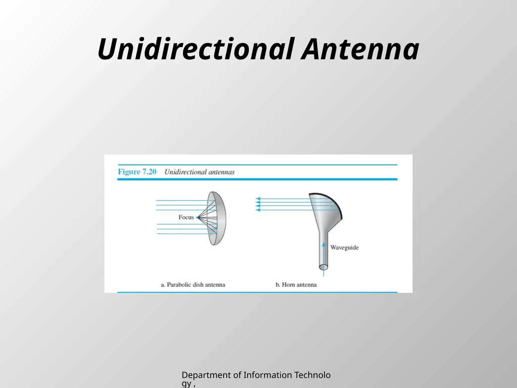
Unidirectional Antenna Department of Information Technology , SIES College of Arts, Science & Commerce (Autonomous)<br>
32
Applications Microwaves are used for unicast communication such as cellular telephones, satellite networks, and wireless LANs. Department of Information Technology , SIES College of Arts, Science & Commerce (Autonomous)<br>
33
Infrared Infrared waves, with frequencies from 300 GHz to 400 THz (wavelengths from 1 mm to 770 nm), can be used for short-range communication.
Infrared waves, having high frequencies, cannot penetrate walls.
This advantageous characteristic prevents interference between one system and another; a short-range communication system in one room cannot be affected by another system in the next room. Department of Information Technology , SIES College of Arts, Science & Commerce (Autonomous)<br>
Infrared waves, having high frequencies, cannot penetrate walls.
This advantageous characteristic prevents interference between one system and another; a short-range communication system in one room cannot be affected by another system in the next room. Department of Information Technology , SIES College of Arts, Science & Commerce (Autonomous)<br>
34
Applications Infrared signals can be used for short-range communication in a closed area using line-of-sight propagation.
The Infrared Data Association (IrDA), an association for sponsoring the use of infrared waves, has established standards for using these signals for communication between devices such as keyboards, mice, PCs, and printers. Department of Information Technology , SIES College of Arts, Science & Commerce (Autonomous)<br>
The Infrared Data Association (IrDA), an association for sponsoring the use of infrared waves, has established standards for using these signals for communication between devices such as keyboards, mice, PCs, and printers. Department of Information Technology , SIES College of Arts, Science & Commerce (Autonomous)<br>