
UNIT-II Sheet Resistance (Rs) IC resistors have a
DP
Published · 110 slides · 0 views

1 / 1

Description
UNIT-II Sheet Resistance (Rs) IC resistors have a specified thickness not under the control of the circuit designer Eliminate t by absorbing it into a new parameter: the sheet resistance (Rs) W t W Wt sq R L
Related Topics
Share
Embed code
Download this presentation From Below
"UNIT-II Sheet Resistance (Rs) IC resistors have a" is the property of its rightful owner. Permission is granted to download and print the materials on this website for personal, non-commercial use only, and to display it on your personal computer provided you do not modify the materials and that you retain all copyright notices contained in the materials. By downloading content from our website, you accept the terms of this agreement.
Presentation Transcript
01
UNIT-II
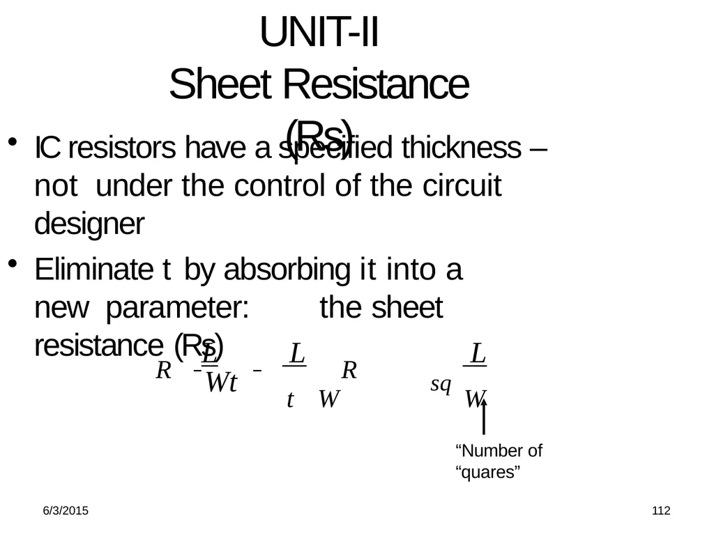
Sheet Resistance (Rs) IC resistors have a specified thickness – not under the control of the circuit designer
Eliminate t by absorbing it into a new parameter: the sheet resistance (Rs) W t W Wt sq R L L R L “Number of “quares” 6/3/2015 112<br>
Eliminate t by absorbing it into a new parameter: the sheet resistance (Rs) W t W Wt sq R L L R L “Number of “quares” 6/3/2015 112<br>
02
6/3/2015 129 BASIC ELECTRICAL PROPERTIES Topics
Basic electrical properties of MOS and BiCMOS circuits:
Ids-Vds relationships
MOS transistor threshold voltage, gm, gds
figure of merit wo
pass transistor
NMOS inverter
Various pull-ups
CMOS inverter analysis and design
BiCMOS inverters<br>
Basic electrical properties of MOS and BiCMOS circuits:
Ids-Vds relationships
MOS transistor threshold voltage, gm, gds
figure of merit wo
pass transistor
NMOS inverter
Various pull-ups
CMOS inverter analysis and design
BiCMOS inverters<br>
03
MOSFET I-V Characteristics
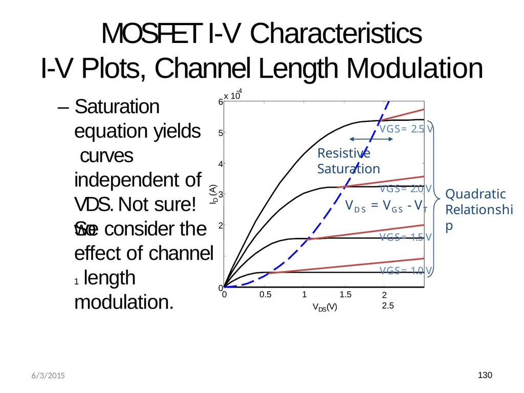
I-V Plots, Channel Length Modulation – Saturation equation yields curves independent of VDS. Not sure! So Quadratic Relationship 0 0.5 1 1.5 0 we consider the effect of channel 1 length modulation. 2 3 4 5 6 x 10 -4 VDS(V) ID (A) VGS= 1.5 V VGS= 1.0 V
2 2.5 VGS= 2.5 V
Resistive Saturation VGS= 2.0 V
VDS = VGS - VT 6/3/2015 130<br>
I-V Plots, Channel Length Modulation – Saturation equation yields curves independent of VDS. Not sure! So Quadratic Relationship 0 0.5 1 1.5 0 we consider the effect of channel 1 length modulation. 2 3 4 5 6 x 10 -4 VDS(V) ID (A) VGS= 1.5 V VGS= 1.0 V
2 2.5 VGS= 2.5 V
Resistive Saturation VGS= 2.0 V
VDS = VGS - VT 6/3/2015 130<br>
04
MOSFET I-V Characteristics Channel Length Modulation Channel Length
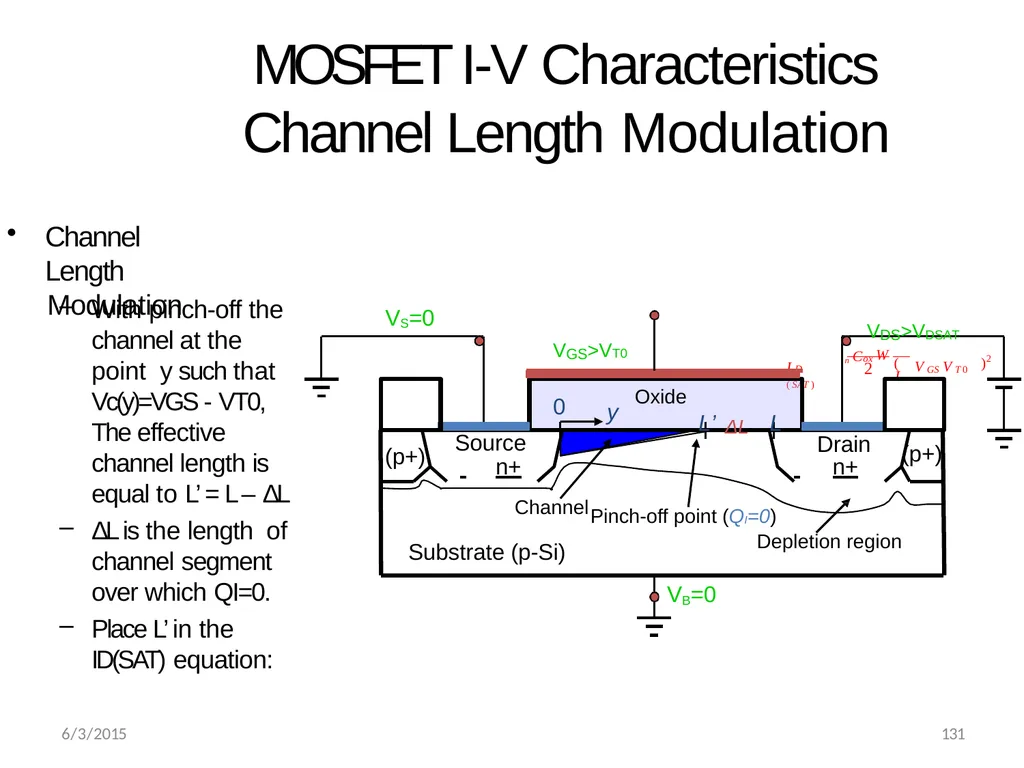
Modulation With pinch-off the channel at the point y such that Vc(y)=VGS - VT0, The effective channel length is equal to L’ = L – ΔL
ΔL is the length of channel segment over which QI=0.
Place L’ in the
ID(SAT) equation: )2 2 I D ( SAT ) L V GS V T 0 n Cox W ( Source
n+ Drain
n+ Substrate (p-Si) (p+) (p+) Oxide 0 y L’ ΔL L Channel Pinch-off point (QI=0)
Depletion region VB=0 VS=0 VGS>VT0 VDS>VDSAT 6/3/2015 131<br>
Modulation With pinch-off the channel at the point y such that Vc(y)=VGS - VT0, The effective channel length is equal to L’ = L – ΔL
ΔL is the length of channel segment over which QI=0.
Place L’ in the
ID(SAT) equation: )2 2 I D ( SAT ) L V GS V T 0 n Cox W ( Source
n+ Drain
n+ Substrate (p-Si) (p+) (p+) Oxide 0 y L’ ΔL L Channel Pinch-off point (QI=0)
Depletion region VB=0 VS=0 VGS>VT0 VDS>VDSAT 6/3/2015 131<br>
05
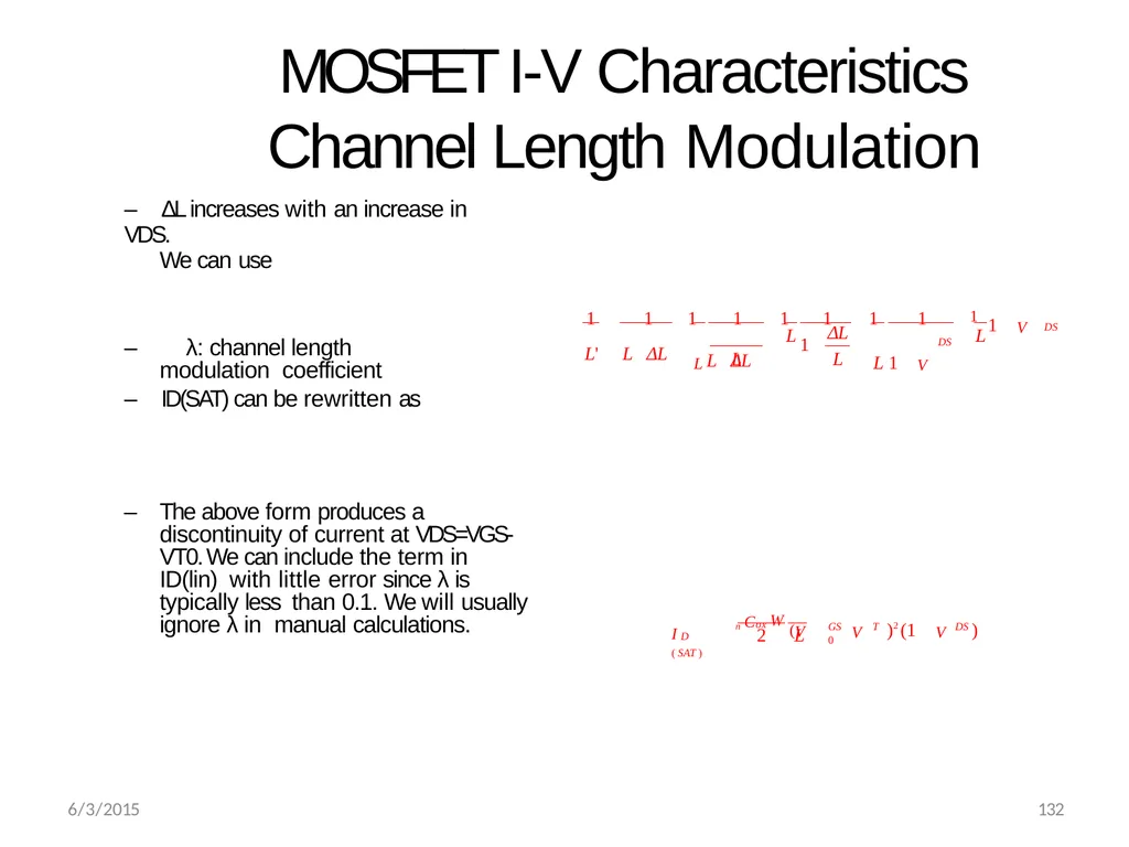
MOSFET I-V Characteristics Channel Length Modulation – ΔL increases with an increase in VDS.
We can use – λ: channel length modulation coefficient
– ID(SAT) can be rewritten as – The above form produces a discontinuity of current at VDS=VGS- VT0. We can include the term in ID(lin) with little error since λ is typically less than 0.1. We will usually ignore λ in manual calculations. L ΔL
L L L DS DS 1 1 V 1 1 1 1 1
L 1 V 1 1
L L ΔL 1 1
L' L ΔL 2 L 6/3/2015 132 DS GS T 0 I D ( SAT ) V )2 (1 V ) n Cox W (V<br>
We can use – λ: channel length modulation coefficient
– ID(SAT) can be rewritten as – The above form produces a discontinuity of current at VDS=VGS- VT0. We can include the term in ID(lin) with little error since λ is typically less than 0.1. We will usually ignore λ in manual calculations. L ΔL
L L L DS DS 1 1 V 1 1 1 1 1
L 1 V 1 1
L L ΔL 1 1
L' L ΔL 2 L 6/3/2015 132 DS GS T 0 I D ( SAT ) V )2 (1 V ) n Cox W (V<br>
06
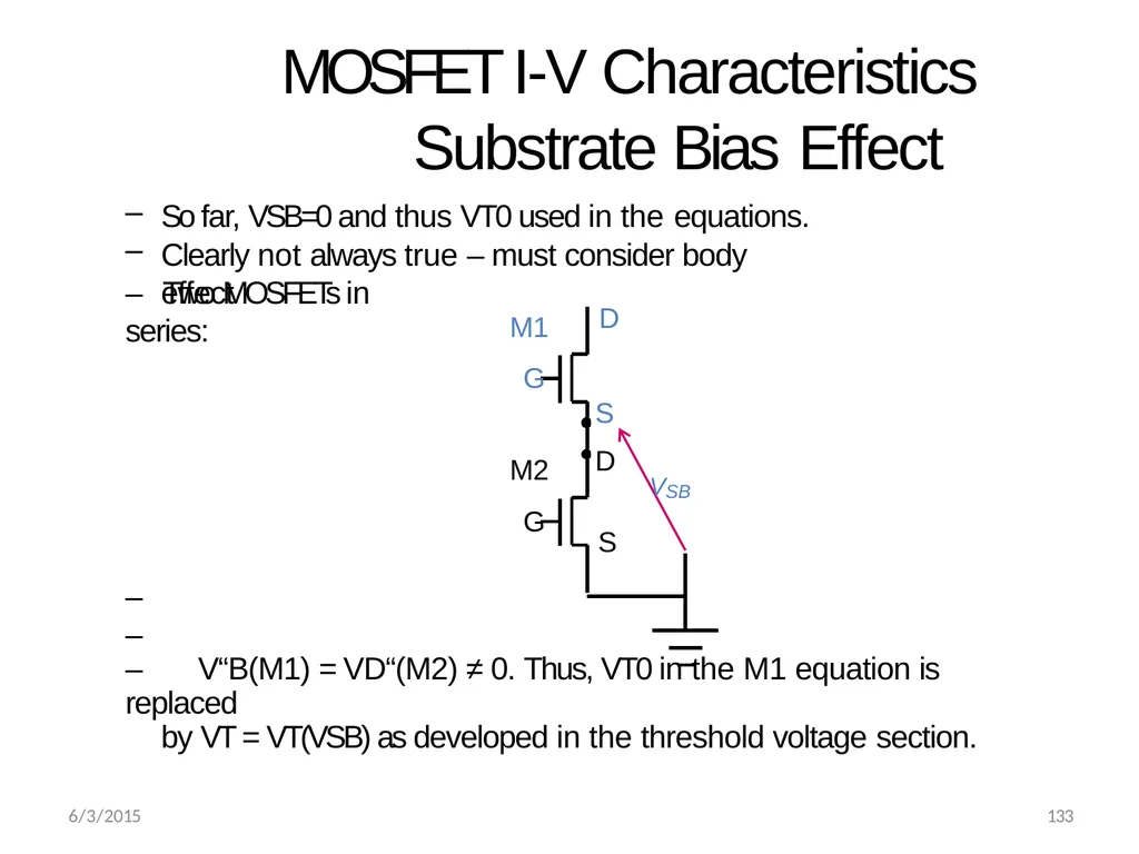
MOSFET I-V Characteristics Substrate Bias Effect So far, VSB=0 and thus VT0 used in the equations.
Clearly not always true – must consider body effect – Two MOSFETs in series: –
–
– V“B(M1) = VD“(M2) ≠ 0. Thus, VT0 in the M1 equation is replaced
by VT = VT(VSB) as developed in the threshold voltage section. D S D M1 G M2 G VSB S 6/3/2015 133<br>
Clearly not always true – must consider body effect – Two MOSFETs in series: –
–
– V“B(M1) = VD“(M2) ≠ 0. Thus, VT0 in the M1 equation is replaced
by VT = VT(VSB) as developed in the threshold voltage section. D S D M1 G M2 G VSB S 6/3/2015 133<br>
07
6/3/2015 134 MOSFET I-V Characteristics Substrate Bias Effect (Cont.) The general form of ID can be written as
ID = f (VGS,VDS,VSB)
which due to the body effect term is non- linear and more difficult to handle in manual calculations<br>
ID = f (VGS,VDS,VSB)
which due to the body effect term is non- linear and more difficult to handle in manual calculations<br>
08
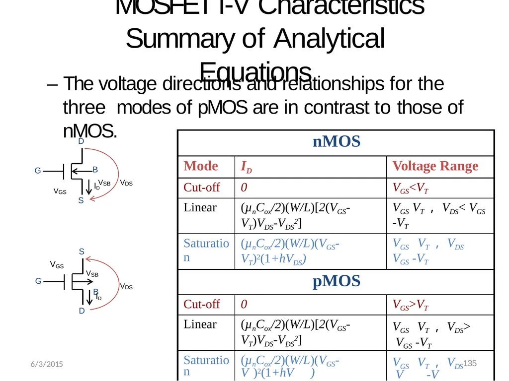
MOSFET I-V Characteristics Summary of Analytical Equations – The voltage directions and relationships for the three modes of pMOS are in contrast to those of nMOS. G D B S VSB VDS VGS ID G S VDS VSB B V GS ID
D 6/3/2015<br>
D 6/3/2015<br>
09
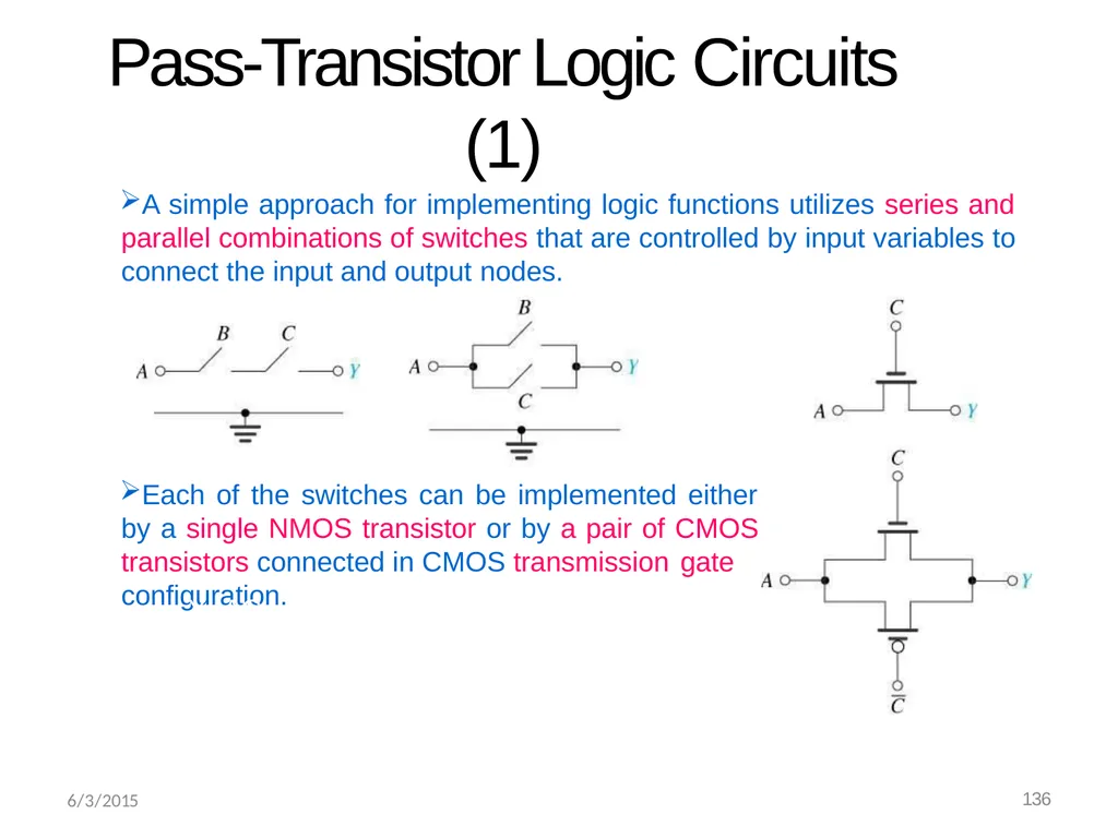
Pass-Transistor Logic Circuits (1) A simple approach for implementing logic functions utilizes series and parallel combinations of switches that are controlled by input variables to connect the input and output nodes. Each of the switches can be implemented either by a single NMOS transistor or by a pair of CMOS transistors connected in CMOS transmission gate configuration. Y=AC 6/3/2015 136<br>
10
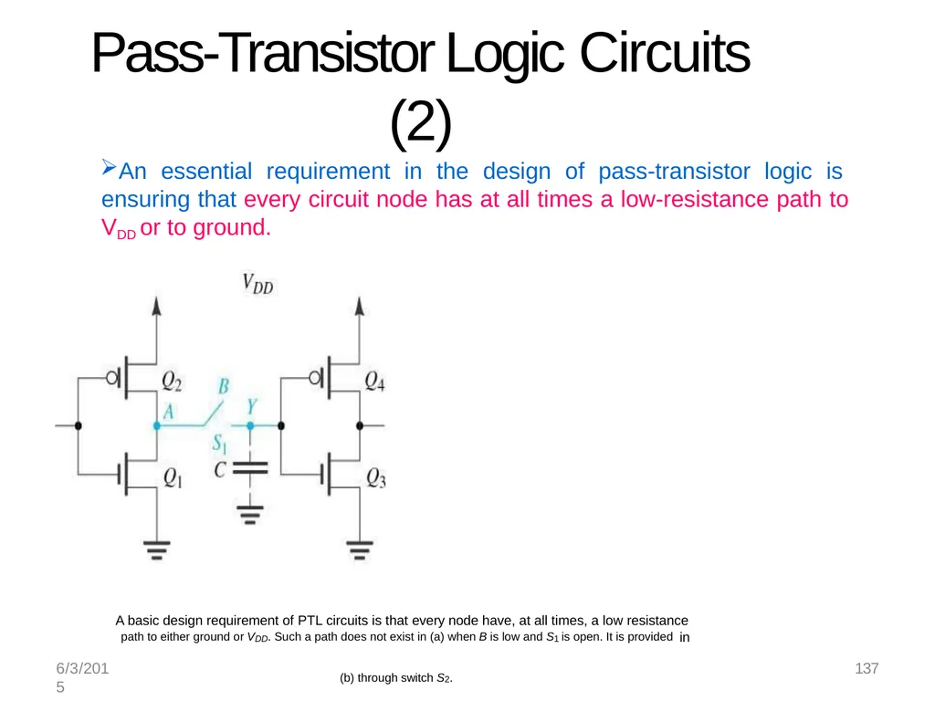
6/3/2015 137 Pass-Transistor Logic Circuits (2) An essential requirement in the design of pass-transistor logic is ensuring that every circuit node has at all times a low-resistance path to VDD or to ground. A basic design requirement of PTL circuits is that every node have, at all times, a low resistance
path to either ground or VDD. Such a path does not exist in (a) when B is low and S1 is open. It is provided in (b) through switch S2.<br>
path to either ground or VDD. Such a path does not exist in (a) when B is low and S1 is open. It is provided in (b) through switch S2.<br>
11
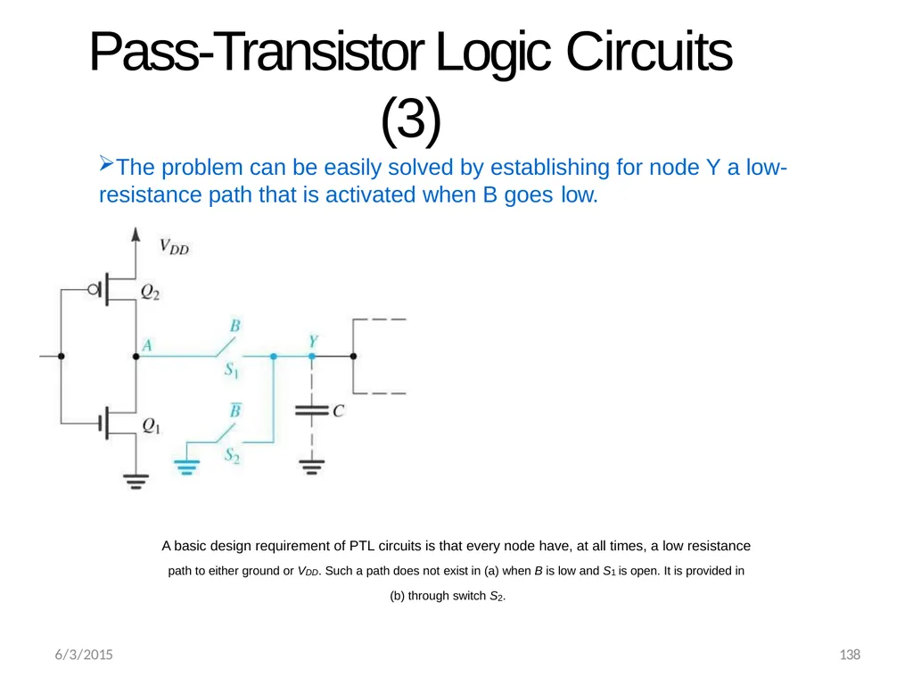
Pass-Transistor Logic Circuits (3) The problem can be easily solved by establishing for node Y a low- resistance path that is activated when B goes low. A basic design requirement of PTL circuits is that every node have, at all times, a low resistance
path to either ground or VDD. Such a path does not exist in (a) when B is low and S1 is open. It is provided in
(b) through switch S2. 6/3/2015 138<br>
path to either ground or VDD. Such a path does not exist in (a) when B is low and S1 is open. It is provided in
(b) through switch S2. 6/3/2015 138<br>
12
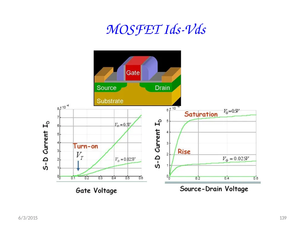
MOSFET Ids-Vds 6/3/2015 139<br>
13
6/3/2015 144 I-V Characteristics In Linear region, Ids depends on
How much charge is in the channel?
How fast is the charge moving?<br>
How much charge is in the channel?
How fast is the charge moving?<br>
14
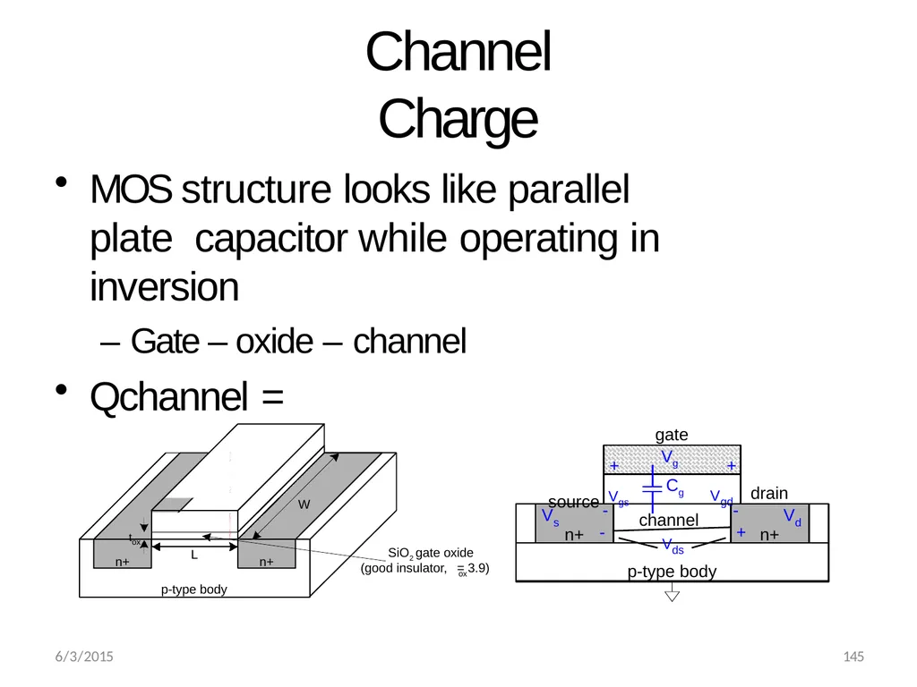
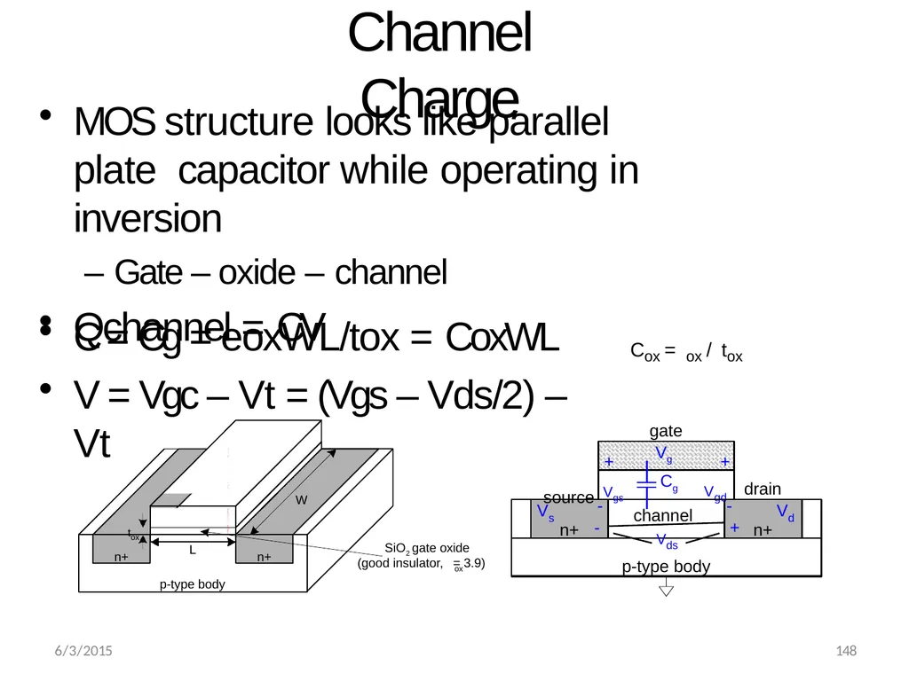
Channel Charge MOS structure looks like parallel plate capacitor while operating in inversion
– Gate – oxide – channel
Qchannel = n+ n+ Vgd gate + + source Vgs -
+ drain Vds
p-type body channel -
- Vg V s V d Cg n+ n+ p-type body W L tox SiO2 gate oxide ox (good insulator, = 3.9) polysilicon gate 6/3/2015 145<br>
– Gate – oxide – channel
Qchannel = n+ n+ Vgd gate + + source Vgs -
+ drain Vds
p-type body channel -
- Vg V s V d Cg n+ n+ p-type body W L tox SiO2 gate oxide ox (good insulator, = 3.9) polysilicon gate 6/3/2015 145<br>
15
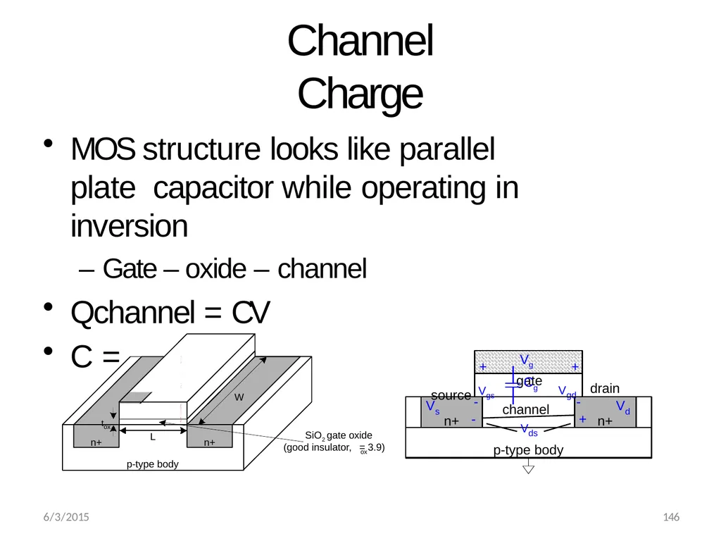
Channel Charge n+ n+ Vgd MOS structure looks like parallel plate capacitor while operating in inversion
– Gate – oxide – channel
Qchannel = CV
C =
gate + + source Vgs -
+ drain Vds
p-type body channel -
- Vg V s V d Cg n+ n+ p-type body W L tox SiO2 gate oxide ox (good insulator, = 3.9) polysilicon gate 6/3/2015 146<br>
– Gate – oxide – channel
Qchannel = CV
C =
gate + + source Vgs -
+ drain Vds
p-type body channel -
- Vg V s V d Cg n+ n+ p-type body W L tox SiO2 gate oxide ox (good insulator, = 3.9) polysilicon gate 6/3/2015 146<br>
16
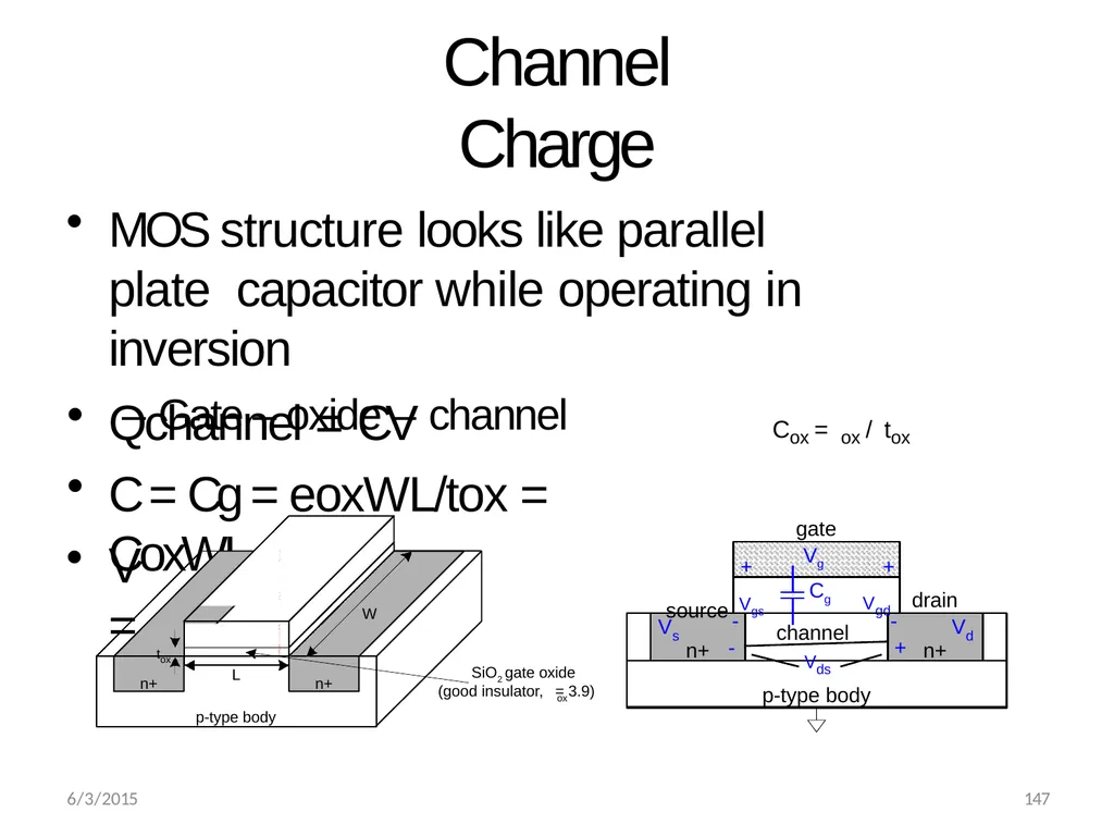
Channel Charge MOS structure looks like parallel plate capacitor while operating in inversion
– Gate – oxide – channel Qchannel = CV
C = Cg = eoxWL/tox = CoxWL V = n+ n+ Vgd gate + + source Vgs -
+ drain Vds
p-type body channel -
- Vg V s V d Cg n+ n+ p-type body W L tox SiO2 gate oxide ox (good insulator, = 3.9) polysilicon gate Cox = ox / tox 6/3/2015 147<br>
– Gate – oxide – channel Qchannel = CV
C = Cg = eoxWL/tox = CoxWL V = n+ n+ Vgd gate + + source Vgs -
+ drain Vds
p-type body channel -
- Vg V s V d Cg n+ n+ p-type body W L tox SiO2 gate oxide ox (good insulator, = 3.9) polysilicon gate Cox = ox / tox 6/3/2015 147<br>
17
Channel Charge MOS structure looks like parallel plate capacitor while operating in inversion
– Gate – oxide – channel
Qchannel = CV C = Cg = eoxWL/tox = CoxWL
V = Vgc – Vt = (Vgs – Vds/2) – Vt n+ n+ Vgd gate + + source Vgs -
+ drain Vds
p-type body channel -
- Vg V s V d Cg n+ n+ p-type body W L tox SiO2 gate oxide ox (good insulator, = 3.9) polysilicon gate Cox = ox / tox 6/3/2015 148<br>
– Gate – oxide – channel
Qchannel = CV C = Cg = eoxWL/tox = CoxWL
V = Vgc – Vt = (Vgs – Vds/2) – Vt n+ n+ Vgd gate + + source Vgs -
+ drain Vds
p-type body channel -
- Vg V s V d Cg n+ n+ p-type body W L tox SiO2 gate oxide ox (good insulator, = 3.9) polysilicon gate Cox = ox / tox 6/3/2015 148<br>
18
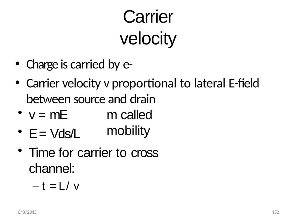
6/3/2015 149 Carrier velocity Charge is carried by e-
Carrier velocity v proportional to lateral E-field between source and drain<br>
Carrier velocity v proportional to lateral E-field between source and drain<br>
19
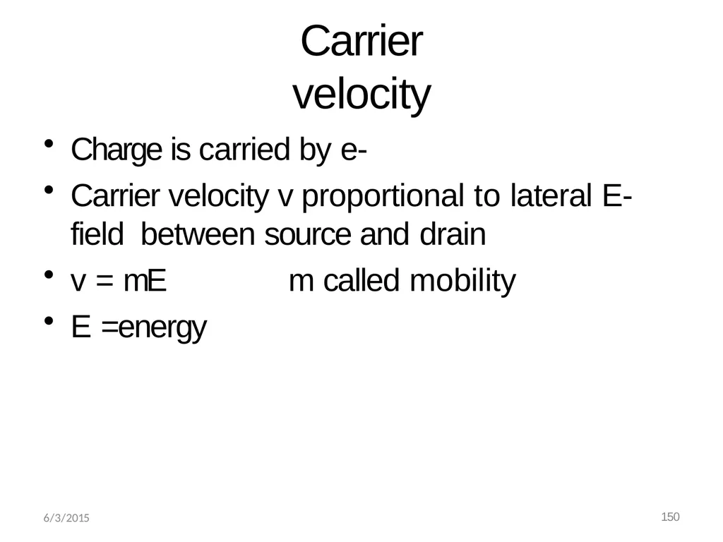
6/3/2015 150 Carrier velocity Charge is carried by e-
Carrier velocity v proportional to lateral E-field between source and drain
v = mE m called mobility
E =energy<br>
Carrier velocity v proportional to lateral E-field between source and drain
v = mE m called mobility
E =energy<br>
20
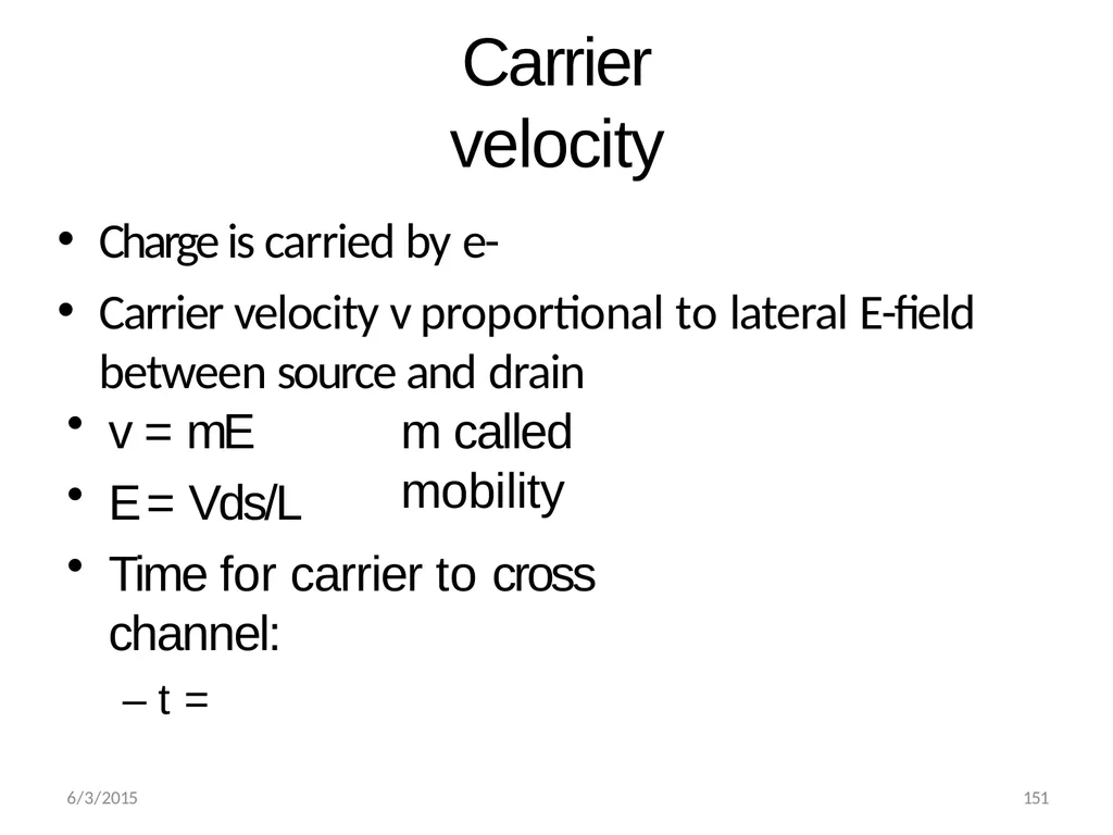
6/3/2015 151 Carrier velocity Charge is carried by e-
Carrier velocity v proportional to lateral E-field between source and drain m called mobility v = mE
E = Vds/L
Time for carrier to cross channel:
– t =<br>
Carrier velocity v proportional to lateral E-field between source and drain m called mobility v = mE
E = Vds/L
Time for carrier to cross channel:
– t =<br>
21
6/3/2015 152 Carrier velocity Charge is carried by e-
Carrier velocity v proportional to lateral E-field between source and drain m called mobility v = mE
E = Vds/L
Time for carrier to cross channel:
– t = L / v<br>
Carrier velocity v proportional to lateral E-field between source and drain m called mobility v = mE
E = Vds/L
Time for carrier to cross channel:
– t = L / v<br>
22
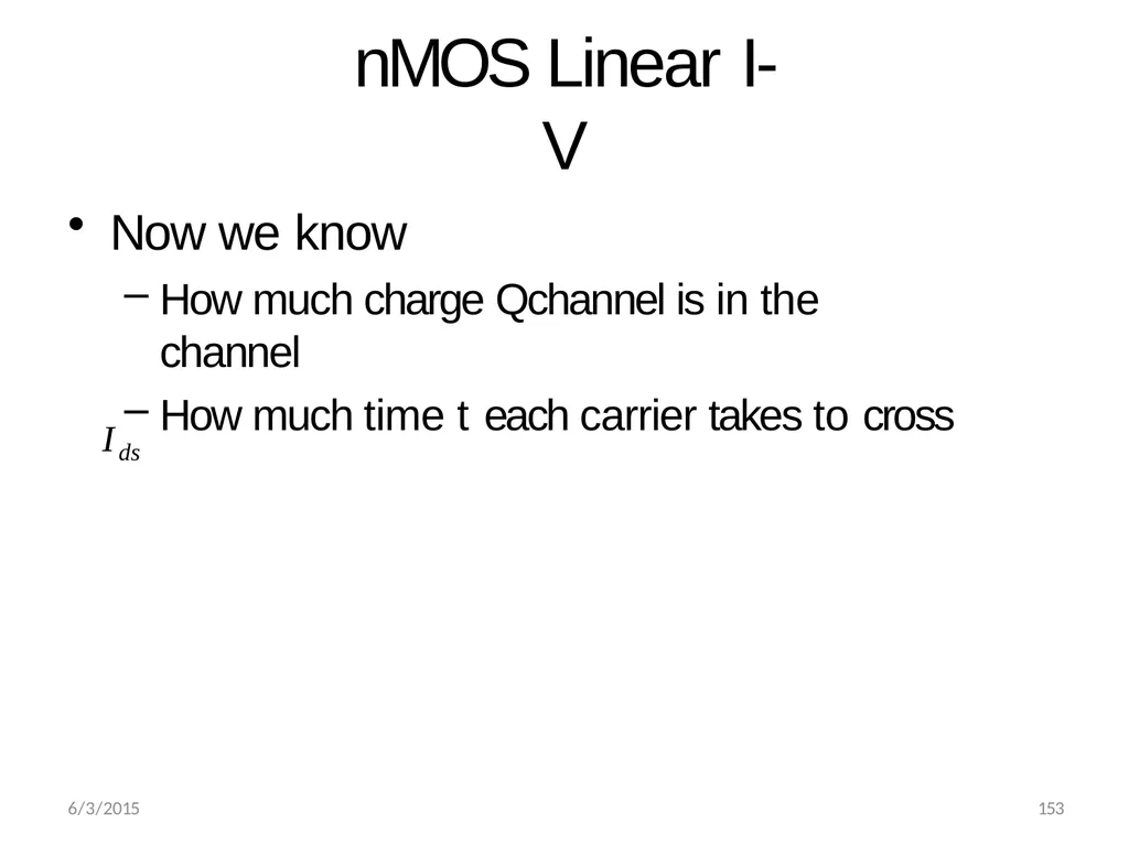
6/3/2015 153 nMOS Linear I-V Now we know
How much charge Qchannel is in the channel
How much time t each carrier takes to cross Ids <br>
How much charge Qchannel is in the channel
How much time t each carrier takes to cross Ids <br>
23
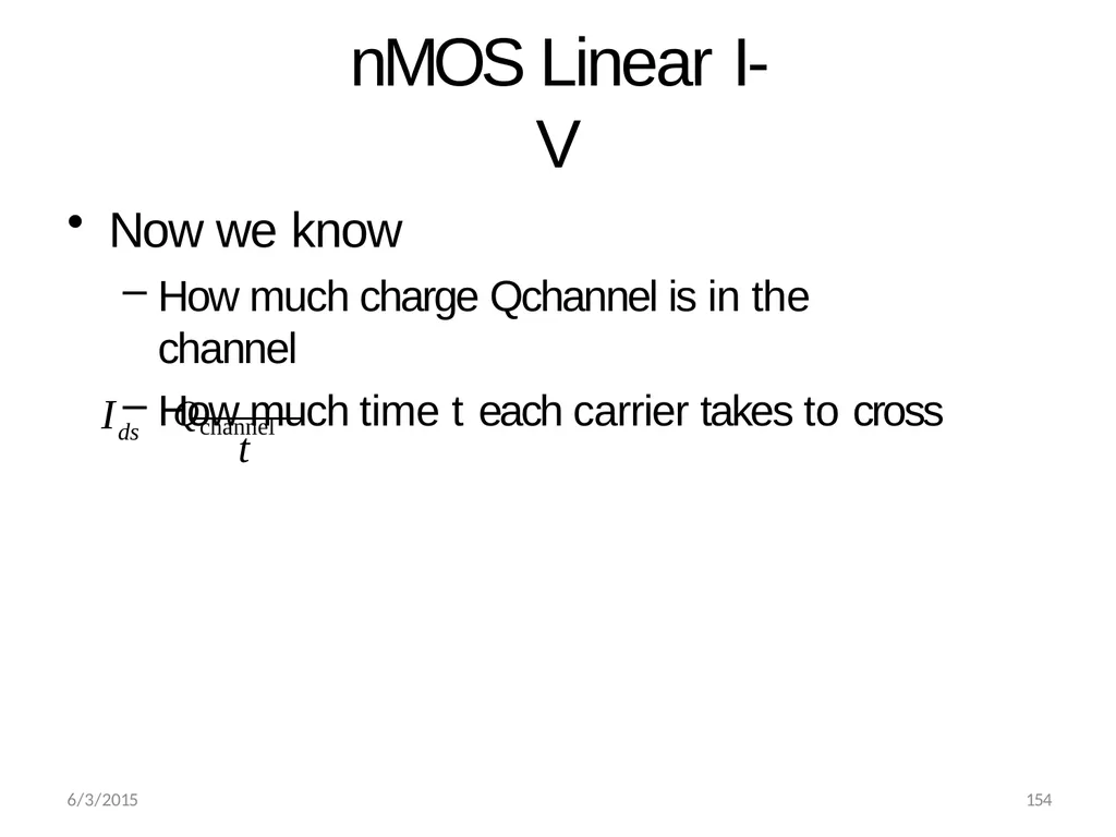
nMOS Linear I-V Now we know
How much charge Qchannel is in the channel
How much time t each carrier takes to cross ds 6/3/2015 154 I t Qchannel <br>
How much charge Qchannel is in the channel
How much time t each carrier takes to cross ds 6/3/2015 154 I t Qchannel <br>
24
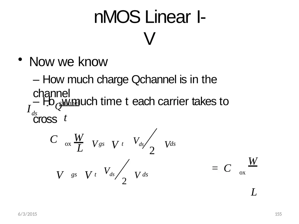
nMOS Linear I-V Now we know
– How much charge Qchannel is in the channel ox 6/3/2015 155 ds gs t ds gs t ds – HoQw much time t each carrier takes to cross I channel
t C V Vds W V V L 2 V V V Vds 2 ox W L = C<br>
– How much charge Qchannel is in the channel ox 6/3/2015 155 ds gs t ds gs t ds – HoQw much time t each carrier takes to cross I channel
t C V Vds W V V L 2 V V V Vds 2 ox W L = C<br>
25
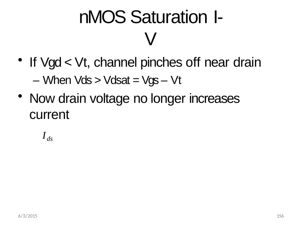
6/3/2015 156 nMOS Saturation I-V If Vgd < Vt, channel pinches off near drain
– When Vds > Vdsat = Vgs – Vt
Now drain voltage no longer increases current Ids <br>
– When Vds > Vdsat = Vgs – Vt
Now drain voltage no longer increases current Ids <br>
26
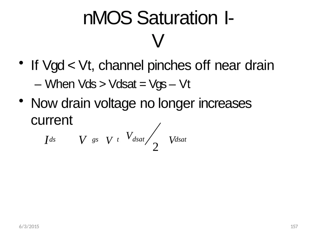
nMOS Saturation I-V If Vgd < Vt, channel pinches off near drain
– When Vds > Vdsat = Vgs – Vt
Now drain voltage no longer increases current ds 6/3/2015 157 gs t dsat V Vdsat I V V 2 <br>
– When Vds > Vdsat = Vgs – Vt
Now drain voltage no longer increases current ds 6/3/2015 157 gs t dsat V Vdsat I V V 2 <br>
27
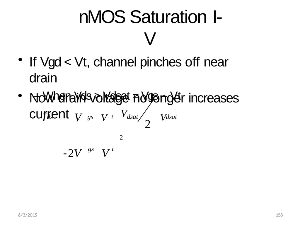
nMOS Saturation I-V If Vgd < Vt, channel pinches off near drain
– When Vds > Vdsat = Vgs – Vt Now drain voltage no longer increases current 6/3/2015 158 2 2 ds gs t dsat gs t V Vdsat I V V 2 V V<br>
– When Vds > Vdsat = Vgs – Vt Now drain voltage no longer increases current 6/3/2015 158 2 2 ds gs t dsat gs t V Vdsat I V V 2 V V<br>
28
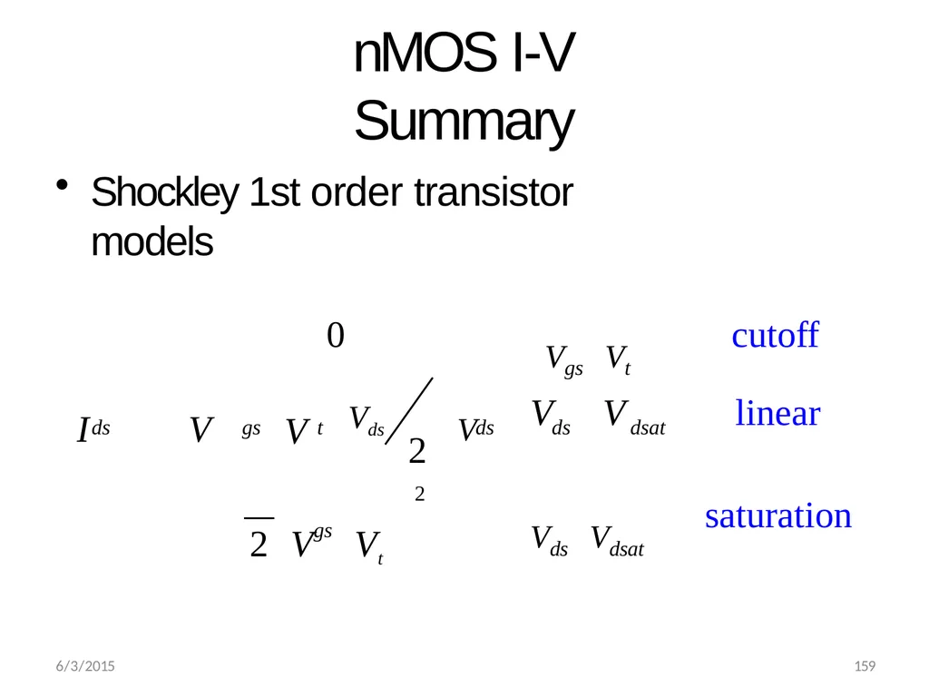
nMOS I-V Summary Shockley 1st order transistor models 6/3/2015 159 2 cutoff linear 0 2 saturation ds gs t ds ds dsat gs Vgs Vt
V Vds V V I V V 2 V Vt Vds Vdsat
<br>
V Vds V V I V V 2 V Vt Vds Vdsat
<br>
29
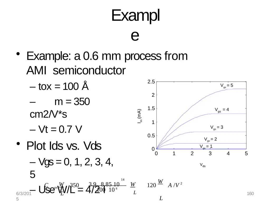
Example Example: a 0.6 mm process from AMI semiconductor – tox = 100 Å
– m = 350 cm2/V*s
– Vt = 0.7 V
Plot Ids vs. Vds
– Vgs = 0, 1, 2, 3, 4, 5
– Use W/L = 4/2 l 2 ox W L A /V 14 W W 3.9 8.8510
L C 350 120 L 100 108 0 1 2 3 4 5 0 0.5 1 1.5 2 2.5 Vds Ids (mA) Vgs = 5 gs V = 4 Vgs = 3 Vgs = 2
Vgs = 1 6/3/2015 160<br>
– m = 350 cm2/V*s
– Vt = 0.7 V
Plot Ids vs. Vds
– Vgs = 0, 1, 2, 3, 4, 5
– Use W/L = 4/2 l 2 ox W L A /V 14 W W 3.9 8.8510
L C 350 120 L 100 108 0 1 2 3 4 5 0 0.5 1 1.5 2 2.5 Vds Ids (mA) Vgs = 5 gs V = 4 Vgs = 3 Vgs = 2
Vgs = 1 6/3/2015 160<br>
30
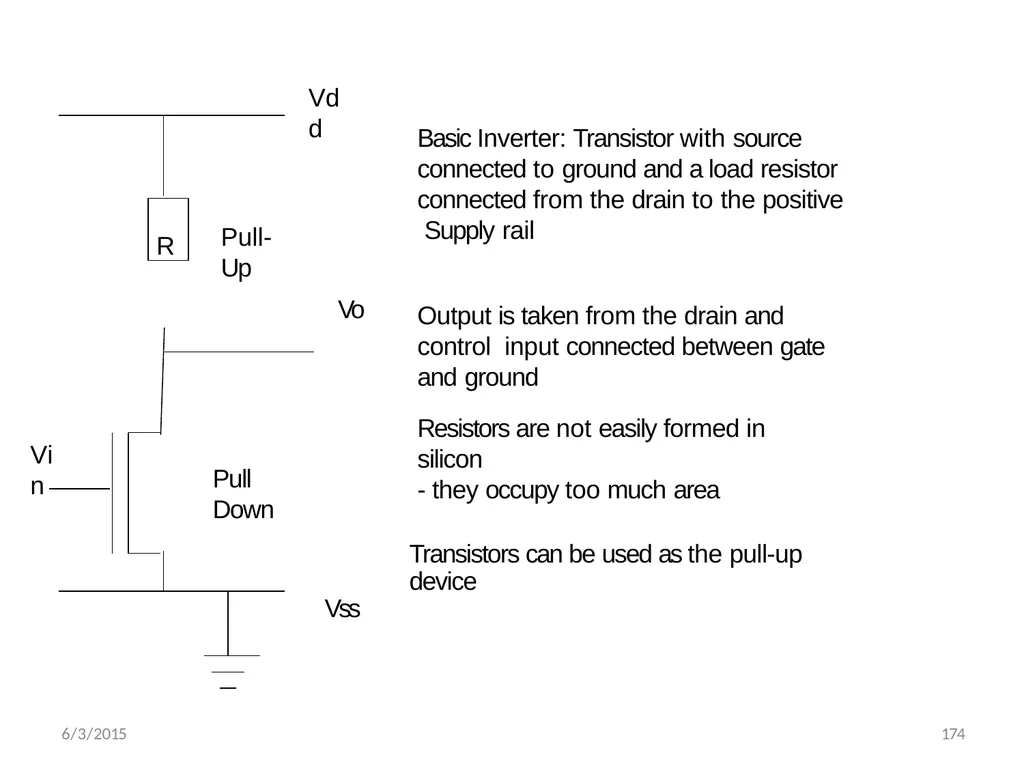
Vdd Vo Vin 6/3/2015 174 R Pull-Up Pull Down Basic Inverter: Transistor with source connected to ground and a load resistor connected from the drain to the positive Supply rail Output is taken from the drain and control input connected between gate and ground Resistors are not easily formed in silicon
- they occupy too much area Transistors can be used as the pull-up device
Vss<br>
- they occupy too much area Transistors can be used as the pull-up device
Vss<br>
31
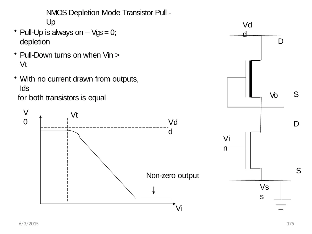
Vdd Vss Vo Vin D S D S Pull-Up is always on – Vgs = 0; depletion Pull-Down turns on when Vin > Vt NMOS Depletion Mode Transistor Pull - Up Vt V0 Vdd Vi With no current drawn from outputs, Ids
for both transistors is equal 6/3/2015 175 Non-zero output<br>
for both transistors is equal 6/3/2015 175 Non-zero output<br>
32
Vgs=0.6 VDD
Vgs=0.4 VDD Vgs=0.2VDD Vgs=0.8VDD Vgs=VDD Ids Vds VDD V o VDD VDD Vin VDD –Vds Ids V ds Vgs=0
Vgs=-0.2 VDD Vgs=-0.4 VDD Vgs=-0.6VDD 6/3/2015 176 Ids
Vgs=0.2VDD<br>
Vgs=0.4 VDD Vgs=0.2VDD Vgs=0.8VDD Vgs=VDD Ids Vds VDD V o VDD VDD Vin VDD –Vds Ids V ds Vgs=0
Vgs=-0.2 VDD Vgs=-0.4 VDD Vgs=-0.6VDD 6/3/2015 176 Ids
Vgs=0.2VDD<br>
33
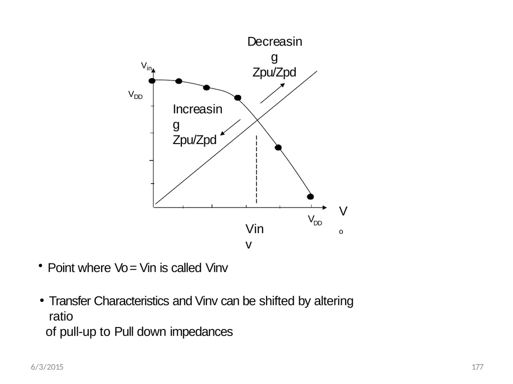
Vo V DD VDD Vin Vinv Decreasing
Zpu/Zpd 6/3/2015 177 Increasing
Zpu/Zpd Point where Vo = Vin is called Vinv
Transfer Characteristics and Vinv can be shifted by altering ratio
of pull-up to Pull down impedances<br>
Zpu/Zpd 6/3/2015 177 Increasing
Zpu/Zpd Point where Vo = Vin is called Vinv
Transfer Characteristics and Vinv can be shifted by altering ratio
of pull-up to Pull down impedances<br>
34
6/3/2015 178 NMOS Depletion Mode Inverter Characteristics Dissipation is high since rail to rail current flows when Vin = Logical 1
Switching of Output from 1 to 0 begins when Vin exceeds Vt of pull down device
When switching the output from 1 to 0, the pull up device is non-saturated initially and this presents a lower resistance through which to charge capacitors (Vds < Vgs – Vt)<br>
Switching of Output from 1 to 0 begins when Vin exceeds Vt of pull down device
When switching the output from 1 to 0, the pull up device is non-saturated initially and this presents a lower resistance through which to charge capacitors (Vds < Vgs – Vt)<br>
35
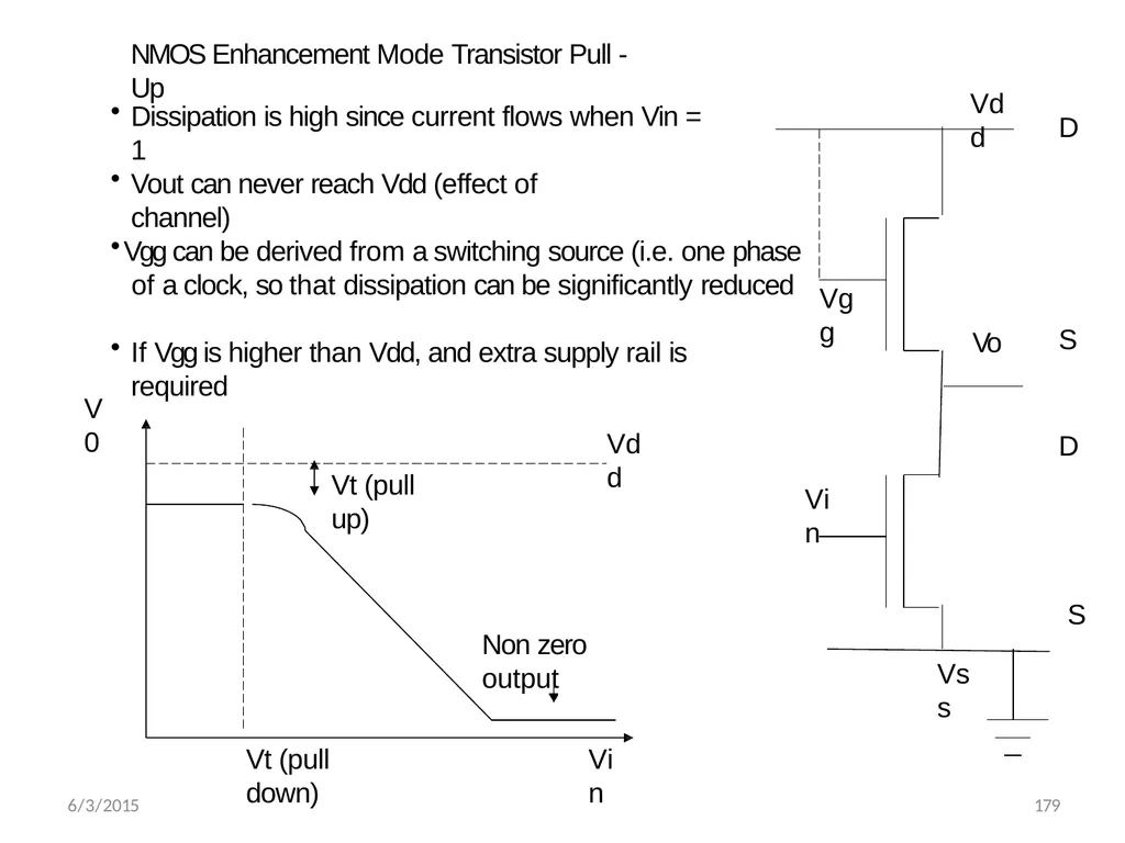
Vss Vo Vin D S D S NMOS Enhancement Mode Transistor Pull - Up Vdd Vgg Vt (pull down) V0 Vdd Vt (pull up) 6/3/2015 179 Non zero output Vin Dissipation is high since current flows when Vin = 1 Vout can never reach Vdd (effect of channel) Vgg can be derived from a switching source (i.e. one phase of a clock, so that dissipation can be significantly reduced If Vgg is higher than Vdd, and extra supply rail is required<br>
36
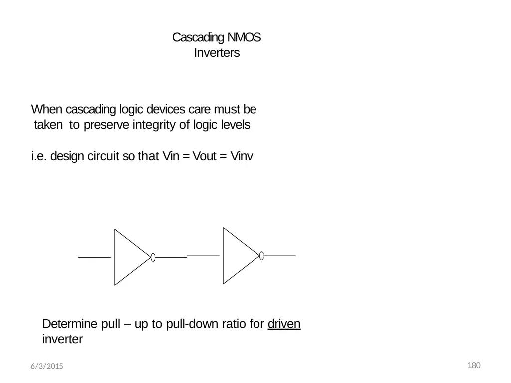
When cascading logic devices care must be taken to preserve integrity of logic levels
i.e. design circuit so that Vin = Vout = Vinv Cascading NMOS Inverters Determine pull – up to pull-down ratio for driven inverter 6/3/2015 180<br>
i.e. design circuit so that Vin = Vout = Vinv Cascading NMOS Inverters Determine pull – up to pull-down ratio for driven inverter 6/3/2015 180<br>
37
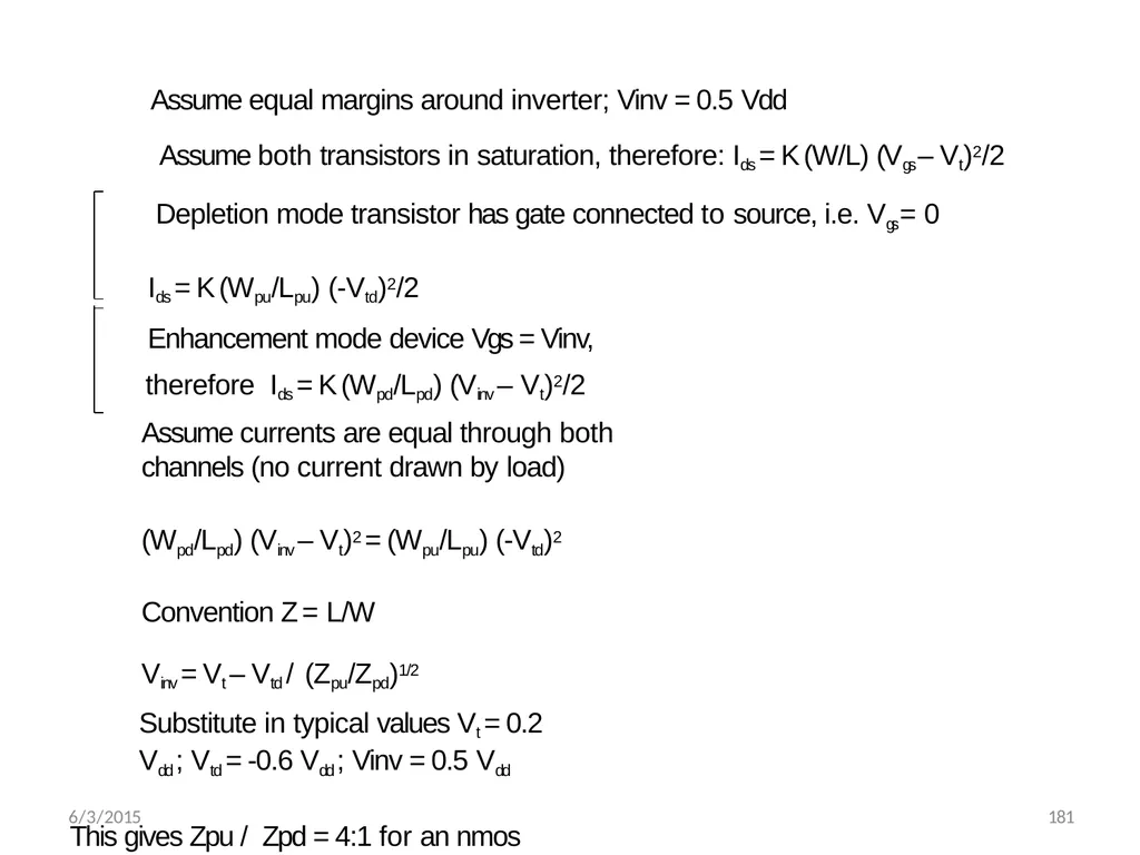
Assume equal margins around inverter; Vinv = 0.5 Vdd
Assume both transistors in saturation, therefore: Ids = K (W/L) (Vgs – Vt)2/2 Depletion mode transistor has gate connected to source, i.e. Vgs = 0
Ids = K (Wpu/Lpu) (-Vtd)2/2
Enhancement mode device Vgs = Vinv, therefore Ids = K (Wpd/Lpd) (Vinv – Vt)2/2
Assume currents are equal through both channels (no current drawn by load)
(Wpd/Lpd) (Vinv – Vt)2 = (Wpu/Lpu) (-Vtd)2 Convention Z = L/W
Vinv = Vt – Vtd / (Zpu/Zpd)1/2
Substitute in typical values Vt = 0.2 Vdd ; Vtd = -0.6 Vdd ; Vinv = 0.5 Vdd
This gives Zpu / Zpd = 4:1 for an nmos inverter directly driven by another inverter 6/3/2015 181<br>
Assume both transistors in saturation, therefore: Ids = K (W/L) (Vgs – Vt)2/2 Depletion mode transistor has gate connected to source, i.e. Vgs = 0
Ids = K (Wpu/Lpu) (-Vtd)2/2
Enhancement mode device Vgs = Vinv, therefore Ids = K (Wpd/Lpd) (Vinv – Vt)2/2
Assume currents are equal through both channels (no current drawn by load)
(Wpd/Lpd) (Vinv – Vt)2 = (Wpu/Lpu) (-Vtd)2 Convention Z = L/W
Vinv = Vt – Vtd / (Zpu/Zpd)1/2
Substitute in typical values Vt = 0.2 Vdd ; Vtd = -0.6 Vdd ; Vinv = 0.5 Vdd
This gives Zpu / Zpd = 4:1 for an nmos inverter directly driven by another inverter 6/3/2015 181<br>
38
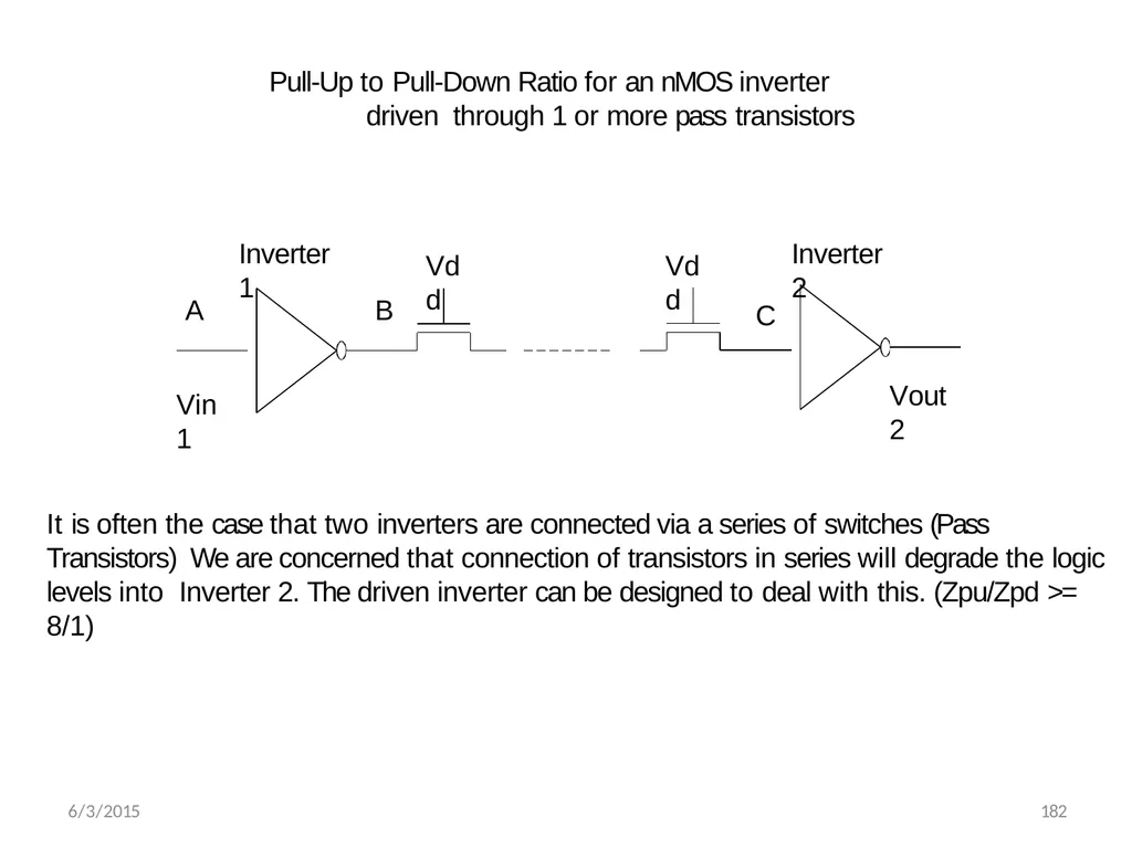
Vdd 6/3/2015 182 Vdd A B C Inverter 1 Inverter 2 Vin1 Vout2 Pull-Up to Pull-Down Ratio for an nMOS inverter driven through 1 or more pass transistors It is often the case that two inverters are connected via a series of switches (Pass Transistors) We are concerned that connection of transistors in series will degrade the logic levels into Inverter 2. The driven inverter can be designed to deal with this. (Zpu/Zpd >= 8/1)<br>
39
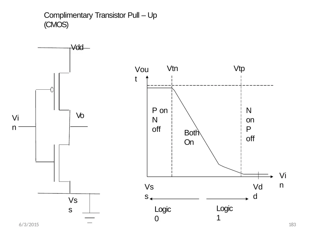
Complimentary Transistor Pull – Up (CMOS)
Vdd Vss Vo Vin Vout Vin Vdd Vss Vtn Vtp Logic 0 6/3/2015 183 Logic 1 P on
N off Both On N on
P off<br>
Vdd Vss Vo Vin Vout Vin Vdd Vss Vtn Vtp Logic 0 6/3/2015 183 Logic 1 P on
N off Both On N on
P off<br>
40
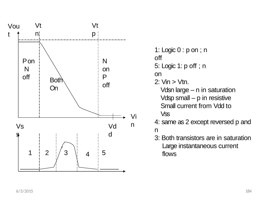
Vout Vin Vdd Vss Vtn Vtp P on N off Both On N on P off 1 2 3 4 5 1: Logic 0 : p on ; n off 6/3/2015 184 5: Logic 1: p off ; n on 2: Vin > Vtn.
Vdsn large – n in saturation Vdsp small – p in resistive Small current from Vdd to Vss 4: same as 2 except reversed p and n 3: Both transistors are in saturation
Large instantaneous current flows<br>
Vdsn large – n in saturation Vdsp small – p in resistive Small current from Vdd to Vss 4: same as 2 except reversed p and n 3: Both transistors are in saturation
Large instantaneous current flows<br>
41
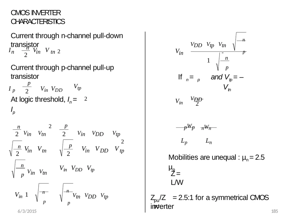
CMOS INVERTER CHARACTERISTICS Current through n-channel pull-down transistor 2 2 in tn n n V V I Current through p-channel pull-up transistor 2 2 p Vtp Vin VDD I p At logic threshold, In = Ip p n tp in DD p in tn n p n Vin VDD Vtp Vin Vtn Vtn VDD Vtp Vin VDD Vtp Vin Vtn V V V V V n
p p n Vin 1 2 2
2
2 2 2 in n
n
p VDD Vtp Vtn V 1 If n = p p
and Vtp = –Vtn 2 VDD Vin pWp nWn
Lp Ln Mobilities are unequal : µn = 2.5 µp 6/3/2015 185 Z = L/W pu pd Z /Z = 2.5:1 for a symmetrical CMOS inverter<br>
p p n Vin 1 2 2
2
2 2 2 in n
n
p VDD Vtp Vtn V 1 If n = p p
and Vtp = –Vtn 2 VDD Vin pWp nWn
Lp Ln Mobilities are unequal : µn = 2.5 µp 6/3/2015 185 Z = L/W pu pd Z /Z = 2.5:1 for a symmetrical CMOS inverter<br>
42
6/3/2015 186 CMOS Inverter Characteristics No current flow for either logical 1 or logical 0 inputs
Full logical 1 and 0 levels are presented at the output
For devices of similar dimensions the p –
channel is slower than the n – channel device<br>
Full logical 1 and 0 levels are presented at the output
For devices of similar dimensions the p –
channel is slower than the n – channel device<br>
43
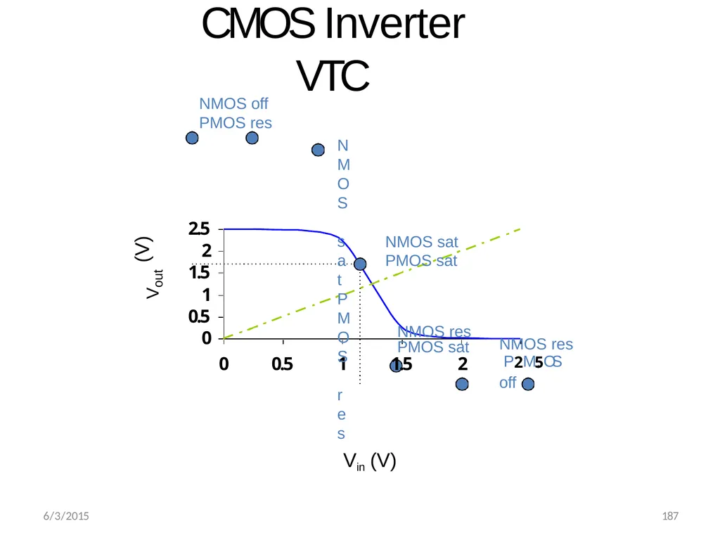
CMOS Inverter VTC 1
0.5
0 2
1.5 2.5 0 0.5 1 Vin (V) Vout (V) NMOS off PMOS res
NMOS sat
PMOS res NMOS sat
PMOS sat NMOS res PMOS sat
1.5 2 NMOS res P2M.5OS off 6/3/2015 187<br>
0.5
0 2
1.5 2.5 0 0.5 1 Vin (V) Vout (V) NMOS off PMOS res
NMOS sat
PMOS res NMOS sat
PMOS sat NMOS res PMOS sat
1.5 2 NMOS res P2M.5OS off 6/3/2015 187<br>
44
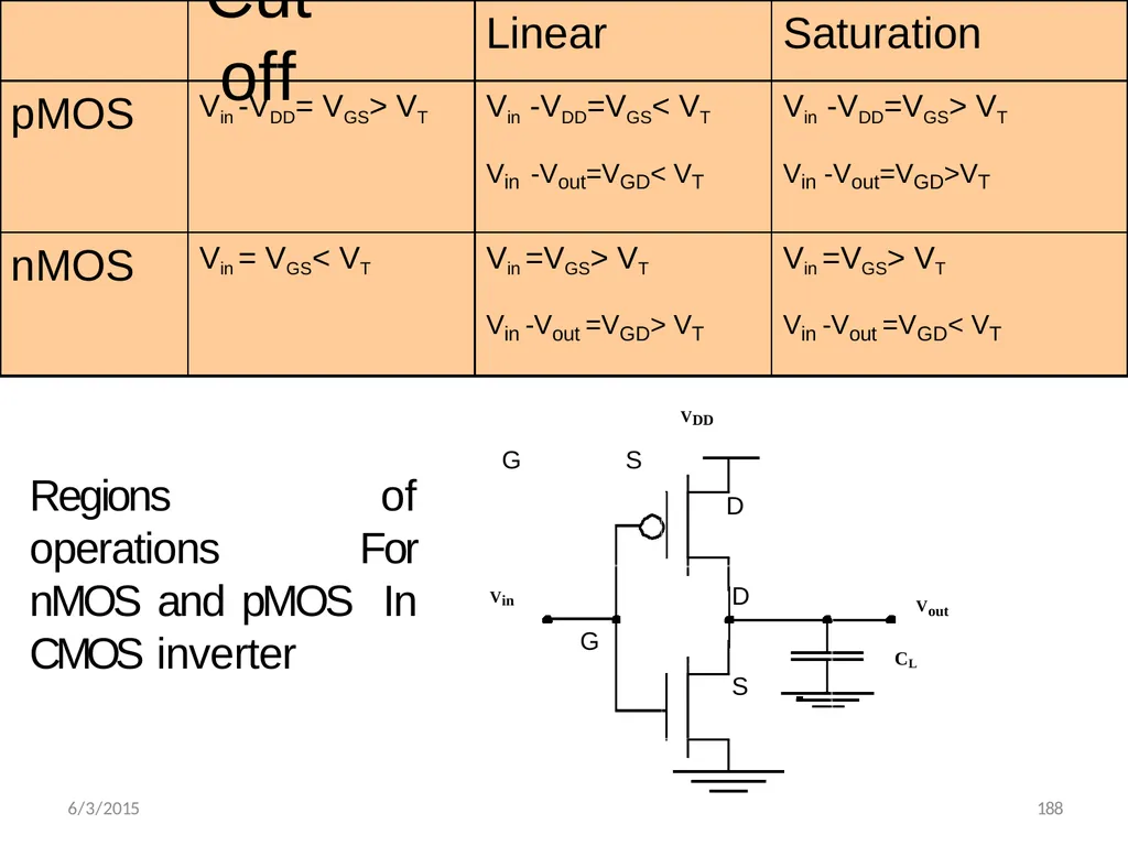
Cutoff Linear Saturation pMOS Vin -VDD= VGS> VT Vin -VDD=VGS< VT
Vin -Vout=VGD< VT Vin -VDD=VGS> VT
Vin -Vout=VGD>VT nMOS Vin = VGS< VT Vin =VGS> VT
Vin -Vout =VGD> VT Vin =VGS> VT
Vin -Vout =VGD< VT VDD 6/3/2015 188 Vin Vout CL G S D D G S Regions of operations For nMOS and pMOS In CMOS inverter<br>
Vin -Vout=VGD< VT Vin -VDD=VGS> VT
Vin -Vout=VGD>VT nMOS Vin = VGS< VT Vin =VGS> VT
Vin -Vout =VGD> VT Vin =VGS> VT
Vin -Vout =VGD< VT VDD 6/3/2015 188 Vin Vout CL G S D D G S Regions of operations For nMOS and pMOS In CMOS inverter<br>
45
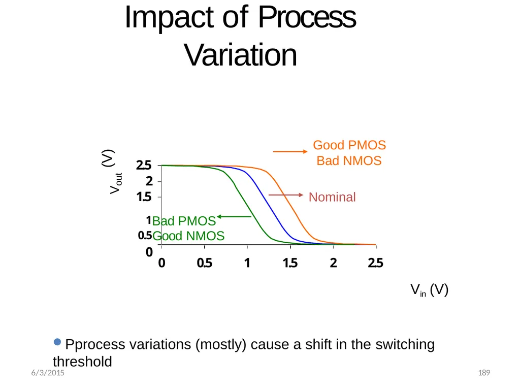
Impact of Process Variation 2.5
2
1.5 0 0.5 1 1.5 2 2.5 Vout (V) Nominal Good PMOS Bad NMOS 1Bad PMOS
0.5Good NMOS
0 Vin (V)
Pprocess variations (mostly) cause a shift in the switching
threshold 6/3/2015 189<br>
2
1.5 0 0.5 1 1.5 2 2.5 Vout (V) Nominal Good PMOS Bad NMOS 1Bad PMOS
0.5Good NMOS
0 Vin (V)
Pprocess variations (mostly) cause a shift in the switching
threshold 6/3/2015 189<br>
46
6/3/2015 190 Cmos Inverter Look at why our NMOS and PMOS inverters might not be the best inverter designs
Introduce the CMOS inverter
Analyze how the CMOS inverter works<br>
Introduce the CMOS inverter
Analyze how the CMOS inverter works<br>
47
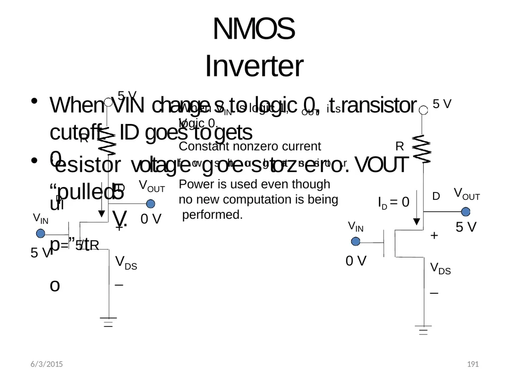
NMOS Inverter When VIN change cutoff. ID goes to 0. 5 V. D D uI p=”5/tRo + V DS _ R 5 V V OUT VIN 5 V 0 V D ID = 0 + VDS
_ 5 V V 6/3/2015 191 OUT VIN 0 V 5 V When V is logic 1, V IN OUT s to logic 0, itsransistor gets logic 0. Constant nonzero current R ‘esistor voltagfleowgs othreousghtotraznseisrtoor.. VOUT “pulled Power is used even though no new computation is being performed.<br>
_ 5 V V 6/3/2015 191 OUT VIN 0 V 5 V When V is logic 1, V IN OUT s to logic 0, itsransistor gets logic 0. Constant nonzero current R ‘esistor voltagfleowgs othreousghtotraznseisrtoor.. VOUT “pulled Power is used even though no new computation is being performed.<br>
48
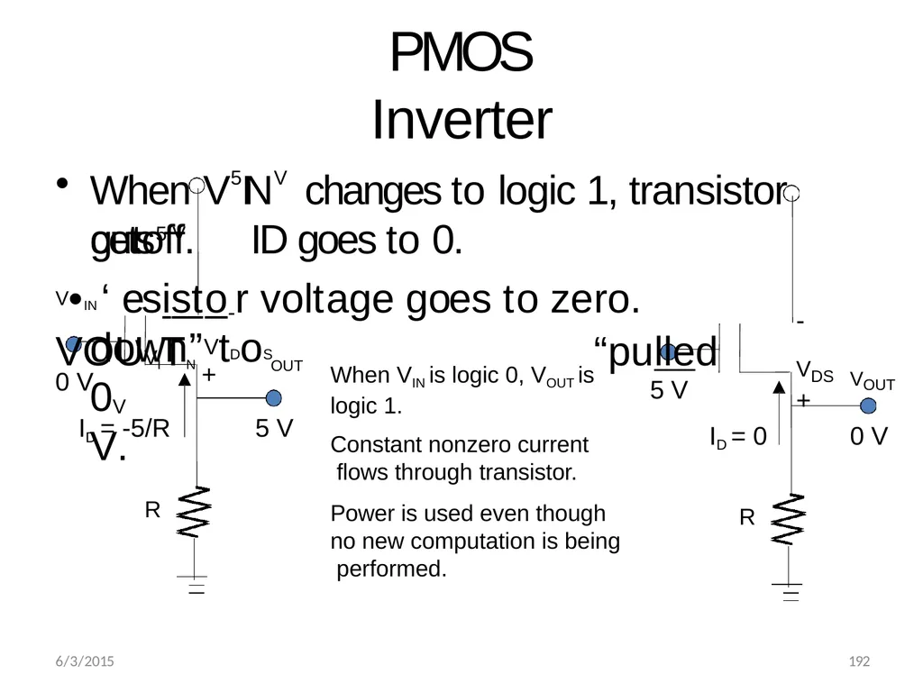
PMOS Inverter OUT ID = -5/R down”VtDoS 0V V. + R 5 V When VIN is logic 0, VOUT is logic 1. Constant nonzero current flows through transistor.
Power is used even though no new computation is being performed. 0 V When V5INV changes to logic 1, transistor gets5 V VOUT ID = 0 - VDS
+ R 0 V 6/3/2015 192 cutoff. ID goes to 0.
V•IN ‘esisto-r voltage goes to zero. VOUVITN “pulled 5 V<br>
Power is used even though no new computation is being performed. 0 V When V5INV changes to logic 1, transistor gets5 V VOUT ID = 0 - VDS
+ R 0 V 6/3/2015 192 cutoff. ID goes to 0.
V•IN ‘esisto-r voltage goes to zero. VOUVITN “pulled 5 V<br>
49
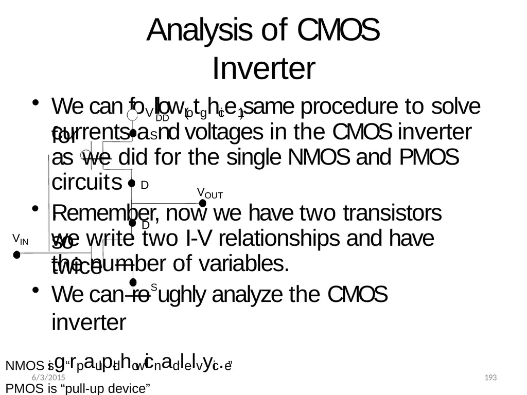
Analysis of CMOS Inverter circuits. Remember, now we have two transistors so we write two I-V relationships and have twice D DD We can foVllow(Lotghice1) same procedure to solve for D currents aSnd voltages in the CMOS inverter as we did for the single NMOS and PMOS VOUT VIN the number of variables.
We can roSughly analyze the CMOS inverter
NMOS isg“rpaulpl-dhowicnadlelvyic.e”
PMOS is “pull-up device”
Each shuts off when not pulling 6/3/2015 193<br>
We can roSughly analyze the CMOS inverter
NMOS isg“rpaulpl-dhowicnadlelvyic.e”
PMOS is “pull-up device”
Each shuts off when not pulling 6/3/2015 193<br>
50
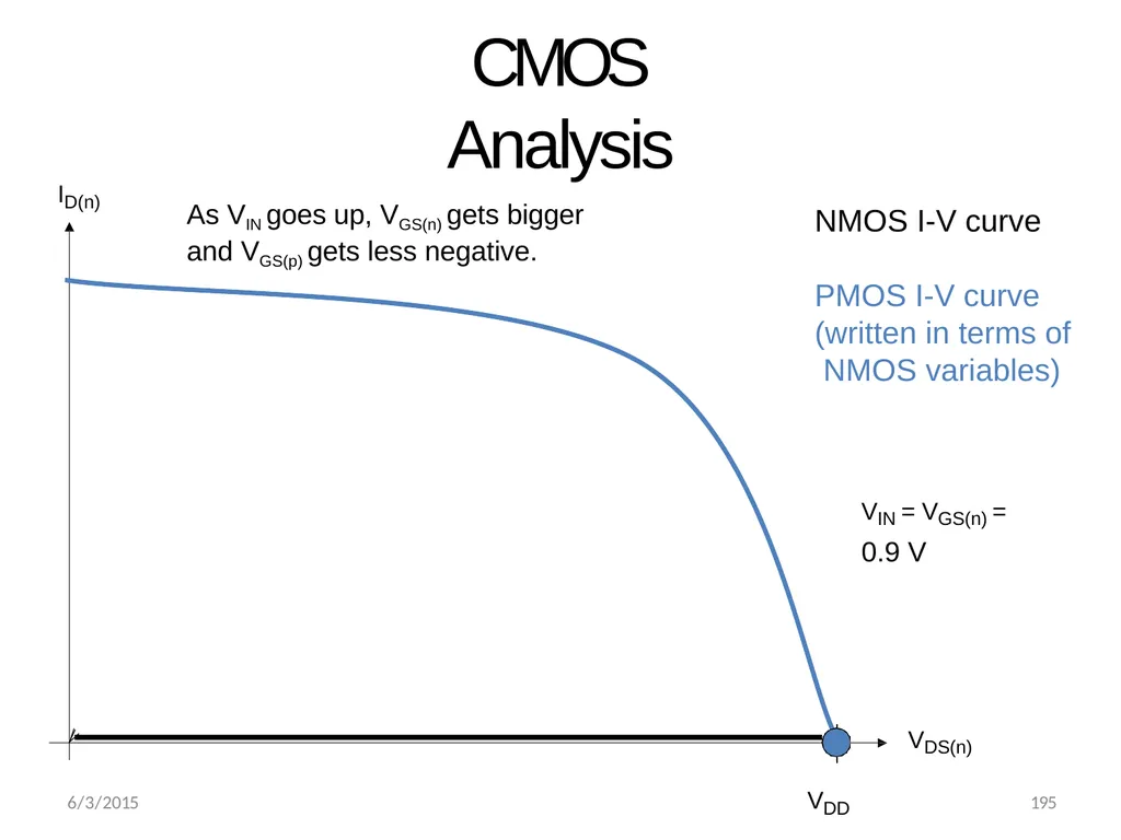
ID(n) NMOS I-V curve PMOS I-V curve (written in terms of NMOS variables) CMOS Analysis VIN = VGS(n) =
0.9 V As VIN goes up, VGS(n) gets bigger
and VGS(p) gets less negative. VDS(n) VDD 6/3/2015 195<br>
0.9 V As VIN goes up, VGS(n) gets bigger
and VGS(p) gets less negative. VDS(n) VDD 6/3/2015 195<br>
51
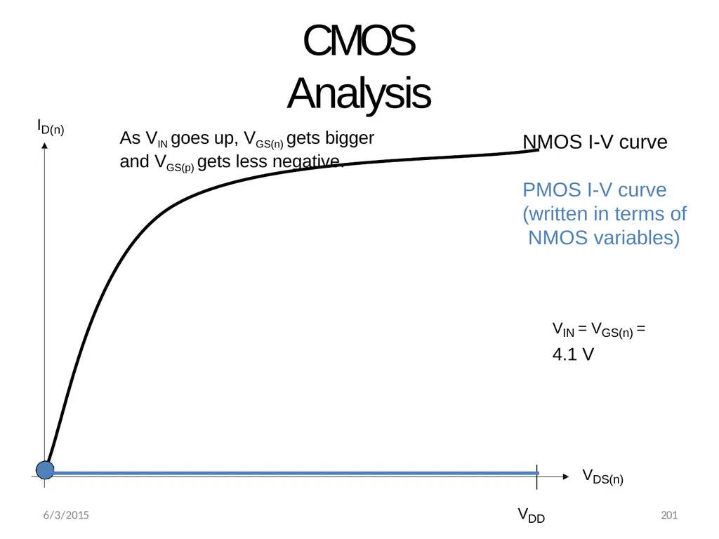
ID(n) NMOS I-V curve PMOS I-V curve (written in terms of NMOS variables) CMOS Analysis VIN = VGS(n) =
4.1 V As VIN goes up, VGS(n) gets bigger
and VGS(p) gets less negative. VDS(n) VDD 6/3/2015 201<br>
4.1 V As VIN goes up, VGS(n) gets bigger
and VGS(p) gets less negative. VDS(n) VDD 6/3/2015 201<br>
52
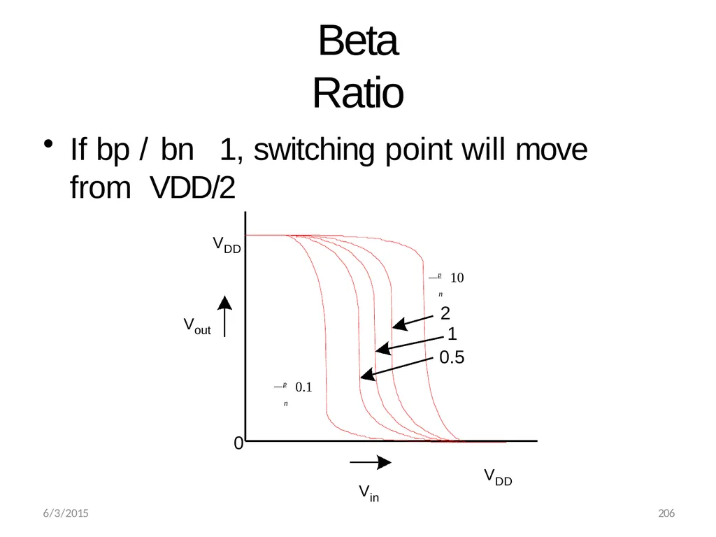
Beta Ratio If bp / bn 1, switching point will move from VDD/2 Vout 0 Vin VDD VDD 2
1
0.5 n p 10 n p 0.1 6/3/2015 206<br>
1
0.5 n p 10 n p 0.1 6/3/2015 206<br>
53
6/3/2015 207 VLSI CIRCUIT DESIGN PROCESSES Topics
VLSI design flow
MOS layers
Stick diagrams
Design Rules and Layout
2 um CMOS design rules for wires
Contacts and Transistors
Layout diagrams for NMOS and
CMOS inverters and gates, Scaling of MOS circuits<br>
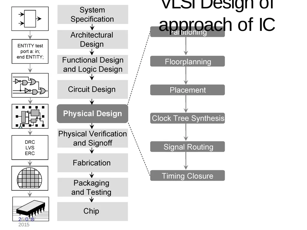
VLSI design flow
MOS layers
Stick diagrams
Design Rules and Layout
2 um CMOS design rules for wires
Contacts and Transistors
Layout diagrams for NMOS and
CMOS inverters and gates, Scaling of MOS circuits<br>
54
VLSI Design of approach of IC 26/038/2015<br>
55
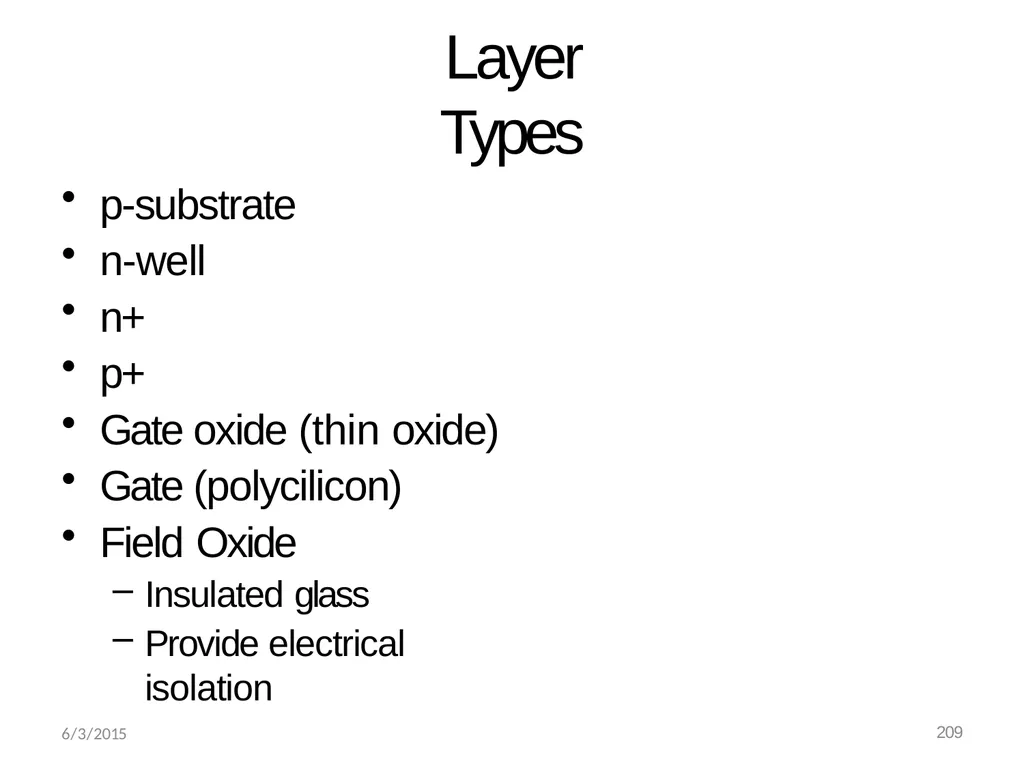
6/3/2015 209 Layer Types p-substrate
n-well
n+
p+
Gate oxide (thin oxide)
Gate (polycilicon)
Field Oxide
Insulated glass
Provide electrical isolation<br>
n-well
n+
p+
Gate oxide (thin oxide)
Gate (polycilicon)
Field Oxide
Insulated glass
Provide electrical isolation<br>
56
Stick diagram
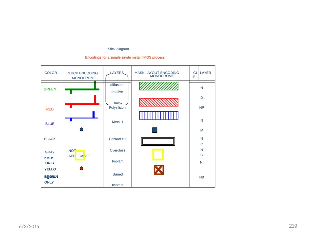
Encodings for a simple single metal nMOS process BROWN 6/3/2015 219<br>
Encodings for a simple single metal nMOS process BROWN 6/3/2015 219<br>
57
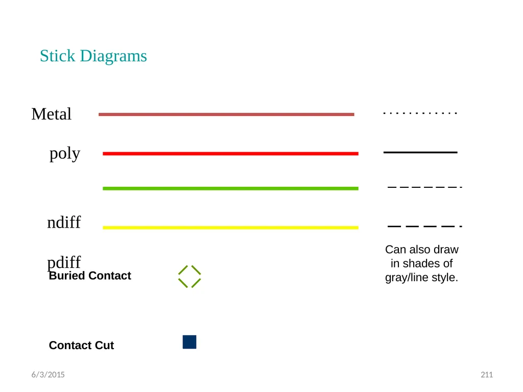
Stick Diagrams Metal
poly ndiff
pdiff Can also draw in shades of gray/line style. Buried Contact Contact Cut 6/3/2015 211<br>
poly ndiff
pdiff Can also draw in shades of gray/line style. Buried Contact Contact Cut 6/3/2015 211<br>
58
6/3/2015 212 Stick Diagrams VLSI design aims to translate circuit concepts onto silicon.
Stick diagrams are a means of capturing topography and layer information using simple diagrams.
Stick diagrams convey layer information through colour codes (or monochrome encoding).
Acts as an interface between symbolic circuit and the actual layout.<br>
Stick diagrams are a means of capturing topography and layer information using simple diagrams.
Stick diagrams convey layer information through colour codes (or monochrome encoding).
Acts as an interface between symbolic circuit and the actual layout.<br>
59
6/3/2015 213 Stick Diagrams Does show all components/vias.
It shows relative placement of components.
Goes one step closer to the layout
Helps plan the layout and routing<br>
It shows relative placement of components.
Goes one step closer to the layout
Helps plan the layout and routing<br>
60
6/3/2015 214 Stick Diagrams Does not show
Exact placement of components
Transistor sizes
Wire lengths, wire widths, tub boundaries.
Any other low level details such as parasitics..<br>
Exact placement of components
Transistor sizes
Wire lengths, wire widths, tub boundaries.
Any other low level details such as parasitics..<br>
61
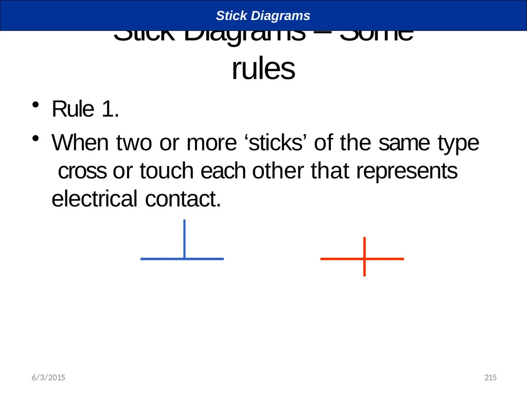
Stick Diagrams – Some rules Rule 1.
When two or more ‘sticks’ of the same type cross or touch each other that represents electrical contact. Stick Diagrams 6/3/2015 215<br>
When two or more ‘sticks’ of the same type cross or touch each other that represents electrical contact. Stick Diagrams 6/3/2015 215<br>
62
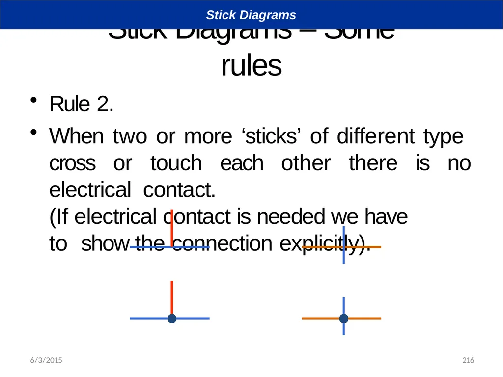
Stick Diagrams – Some rules Rule 2.
When two or more ‘sticks’ of different type cross or touch each other there is no electrical contact.
(If electrical contact is needed we have to show the connection explicitly). Stick Diagrams 6/3/2015 216<br>
When two or more ‘sticks’ of different type cross or touch each other there is no electrical contact.
(If electrical contact is needed we have to show the connection explicitly). Stick Diagrams 6/3/2015 216<br>
63
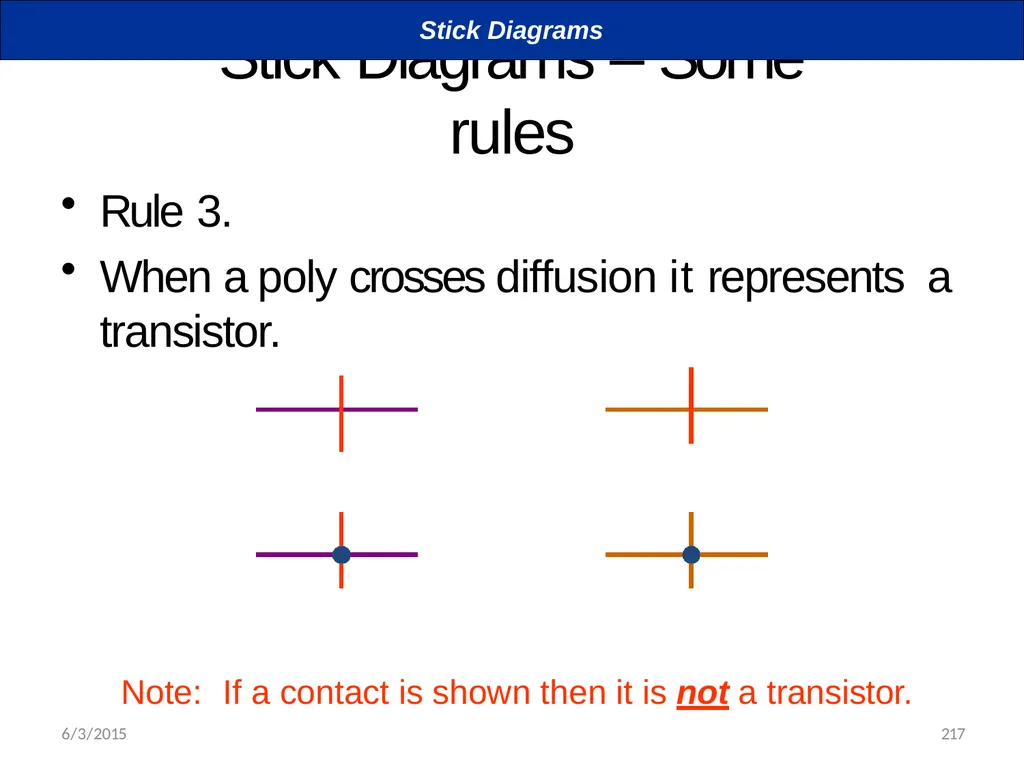
Stick Diagrams – Some rules Rule 3.
When a poly crosses diffusion it represents a transistor. Note: If a contact is shown then it is not a transistor. Stick Diagrams 6/3/2015 217<br>
When a poly crosses diffusion it represents a transistor. Note: If a contact is shown then it is not a transistor. Stick Diagrams 6/3/2015 217<br>
64
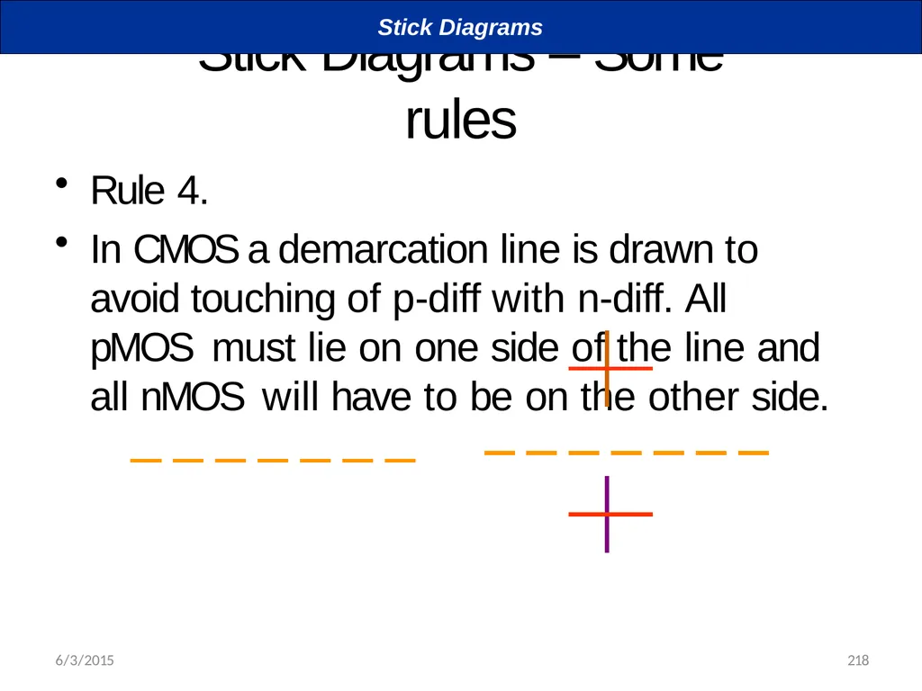
Stick Diagrams – Some rules Rule 4.
In CMOS a demarcation line is drawn to avoid touching of p-diff with n-diff. All pMOS must lie on one side of the line and all nMOS will have to be on the other side. Stick Diagrams 6/3/2015 218<br>
In CMOS a demarcation line is drawn to avoid touching of p-diff with n-diff. All pMOS must lie on one side of the line and all nMOS will have to be on the other side. Stick Diagrams 6/3/2015 218<br>
65
6/3/2015 219<br>
66
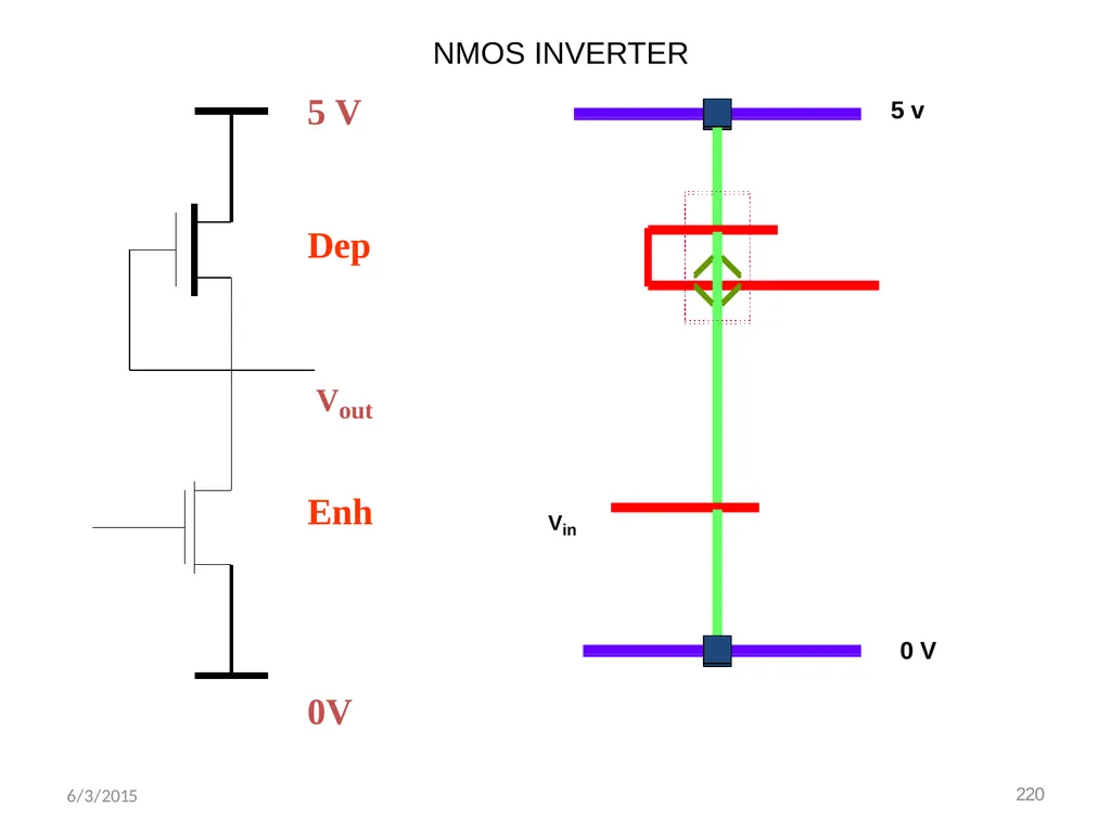
5 V Dep Vout Enh 0V 0 V Vin 5 v NMOS INVERTER 6/3/2015 220<br>
67
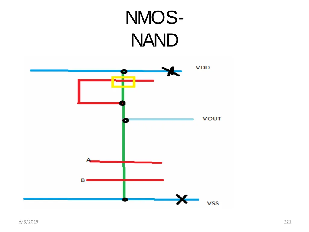
NMOS-NAND 6/3/2015 221<br>
68
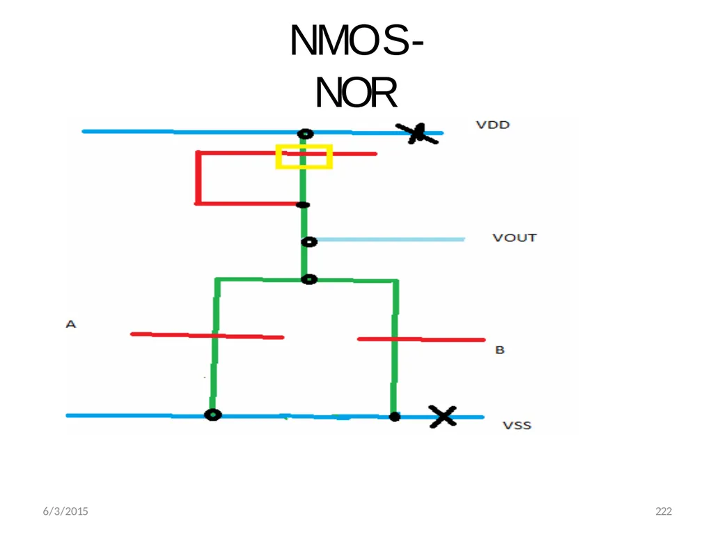
NMOS-NOR 6/3/2015 222<br>
69
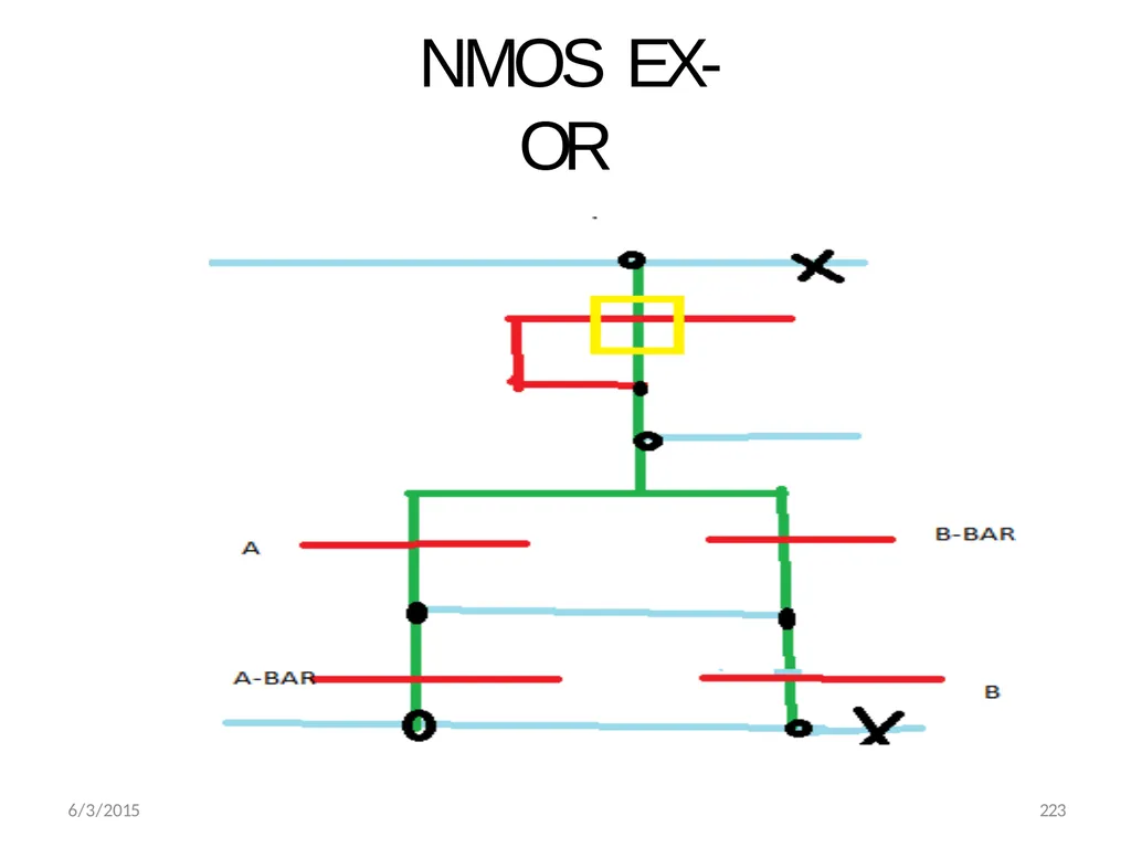
NMOS EX-OR 6/3/2015 223<br>
70
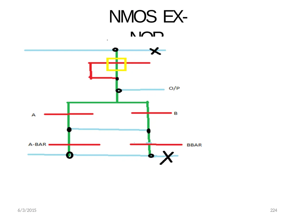
NMOS EX-NOR 6/3/2015 224<br>
71
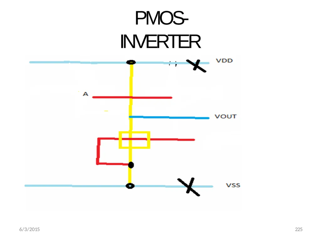
PMOS-INVERTER 6/3/2015 225<br>
72
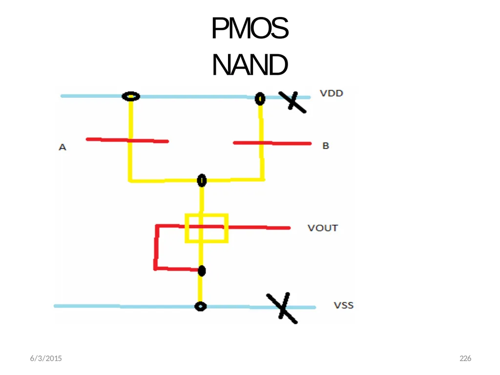
PMOS NAND 6/3/2015 226<br>
73
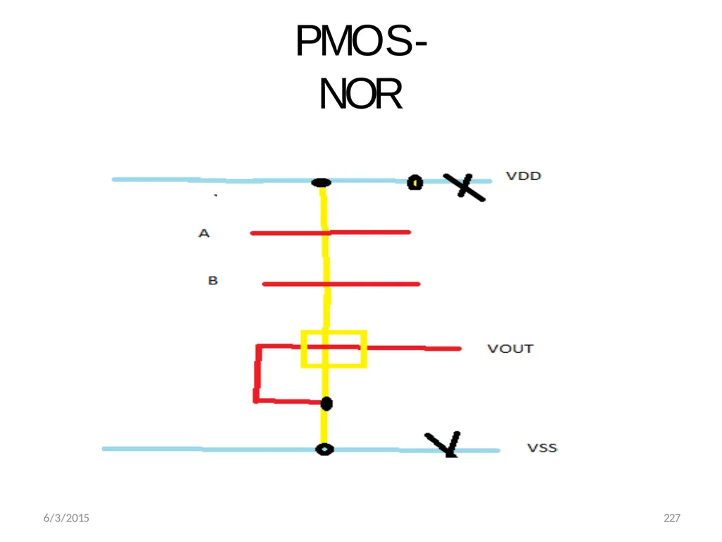
PMOS-NOR 6/3/2015 227<br>
74
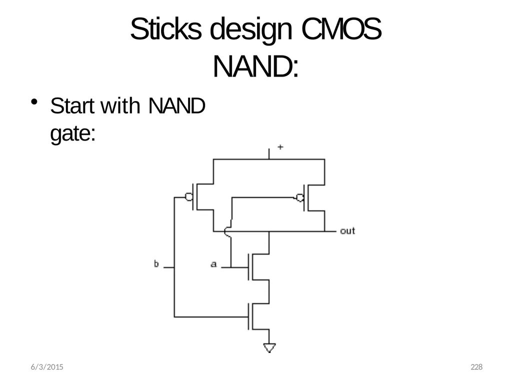
Sticks design CMOS NAND: Start with NAND gate: 6/3/2015 228<br>
75
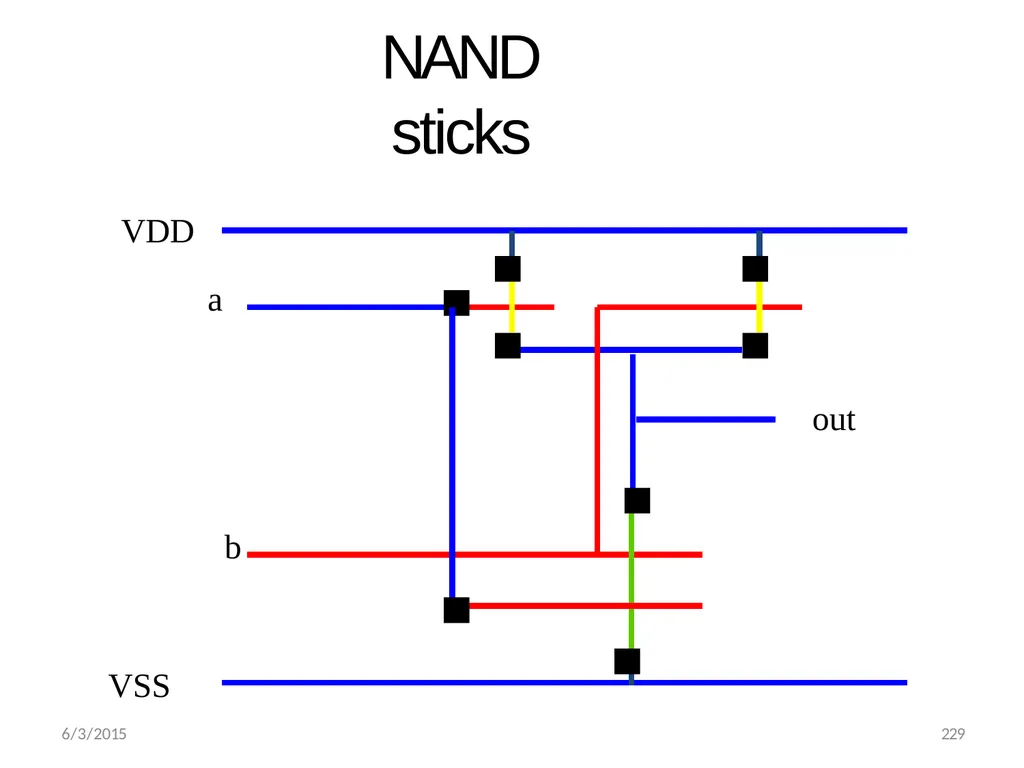
NAND sticks VDD
a out b
VSS 6/3/2015 229<br>
a out b
VSS 6/3/2015 229<br>
76
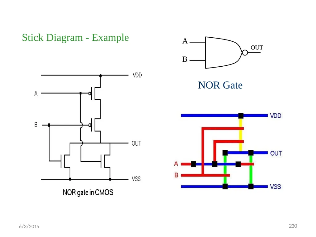
Stick Diagram - Example OUT B
NOR Gate A 6/3/2015 230<br>
NOR Gate A 6/3/2015 230<br>
77
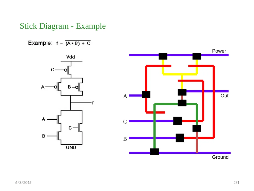
Stick Diagram - Example Power 6/3/2015 231 Ground C
B Out A<br>
B Out A<br>
78
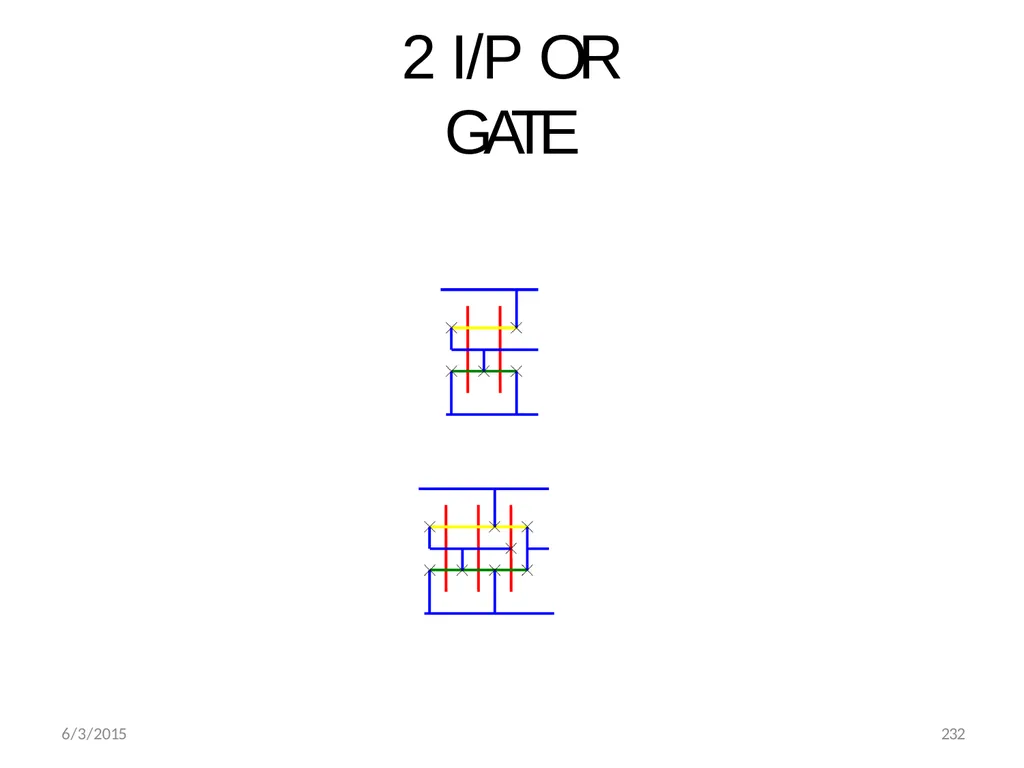
2 I/P OR GATE 6/3/2015 232<br>
79
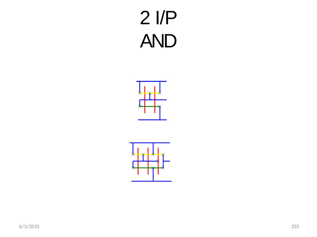
2 I/P AND 6/3/2015 233<br>
80
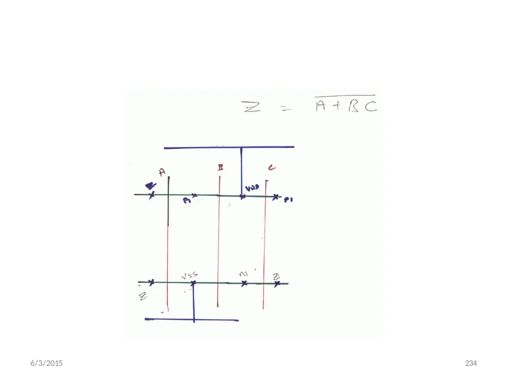
6/3/2015 234<br>
81
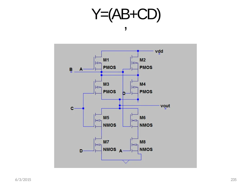
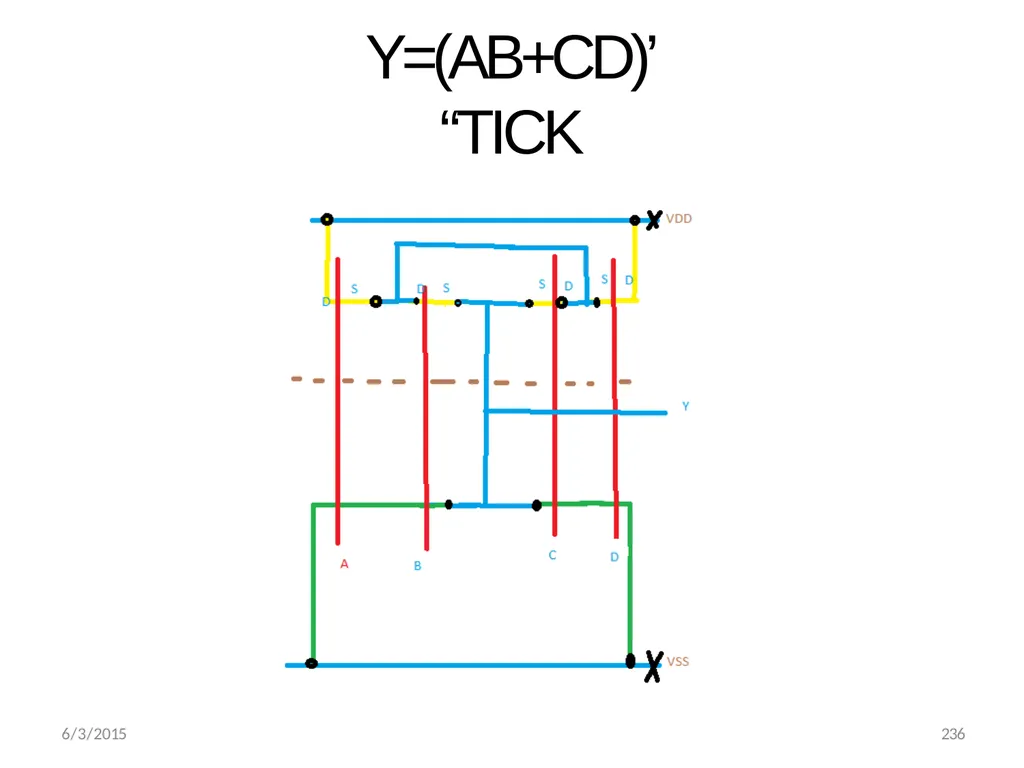
Y=(AB+CD)’ 6/3/2015 235<br>
82
Y=(AB+CD)’ “TICK 6/3/2015 236<br>
83
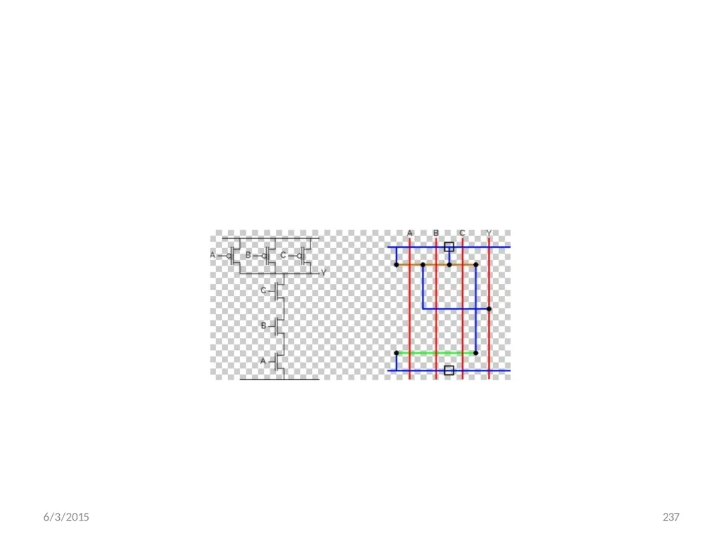
6/3/2015 237<br>
84
6/3/2015 238 Design Rules Design rules are a set of geometrical specifications that dictate the design of the layout masks
A design rule set provides numerical values
For minimum dimensions
For minimum line spacings
Design rules must be followed to insure functional structures on the fabricated chip
Design rules change with technological advances (www.mosis.org)<br>
A design rule set provides numerical values
For minimum dimensions
For minimum line spacings
Design rules must be followed to insure functional structures on the fabricated chip
Design rules change with technological advances (www.mosis.org)<br>
85
6/3/2015 248 Design Rules Minimum length or width of a feature on a layer is 2
Why?
To allow for shape contraction
Minimum separation of features on a layer is 2
Why?
To ensure adequate continuity of the intervening materials.<br>
Why?
To allow for shape contraction
Minimum separation of features on a layer is 2
Why?
To ensure adequate continuity of the intervening materials.<br>
86
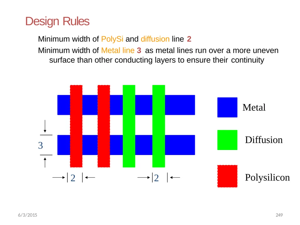
Design Rules Minimum width of PolySi and diffusion line 2
Minimum width of Metal line 3 as metal lines run over a more uneven surface than other conducting layers to ensure their continuity Metal Diffusion Polysilicon 6/3/2015 249<br>
Minimum width of Metal line 3 as metal lines run over a more uneven surface than other conducting layers to ensure their continuity Metal Diffusion Polysilicon 6/3/2015 249<br>
87
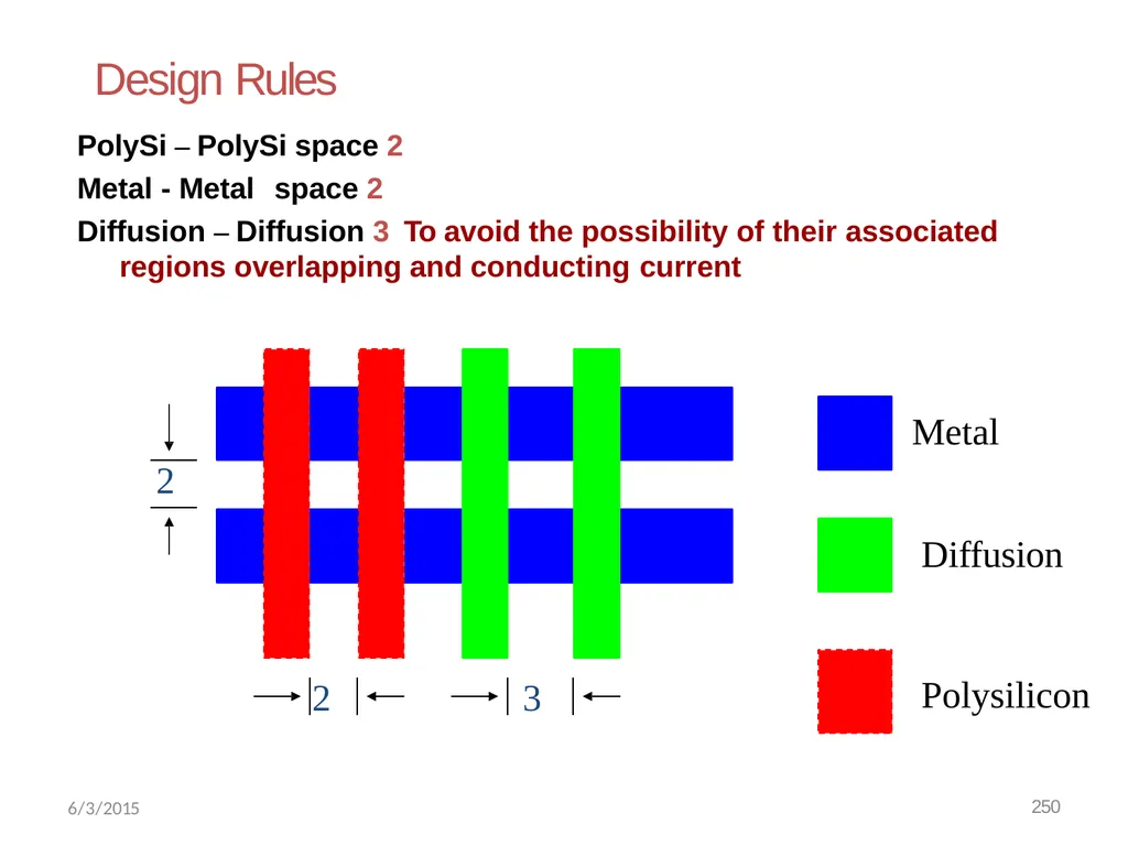
Design Rules PolySi – PolySi space 2 Metal - Metal space 2
Diffusion – Diffusion 3 To avoid the possibility of their associated regions overlapping and conducting current Metal Diffusion Polysilicon 6/3/2015 250<br>
Diffusion – Diffusion 3 To avoid the possibility of their associated regions overlapping and conducting current Metal Diffusion Polysilicon 6/3/2015 250<br>
88
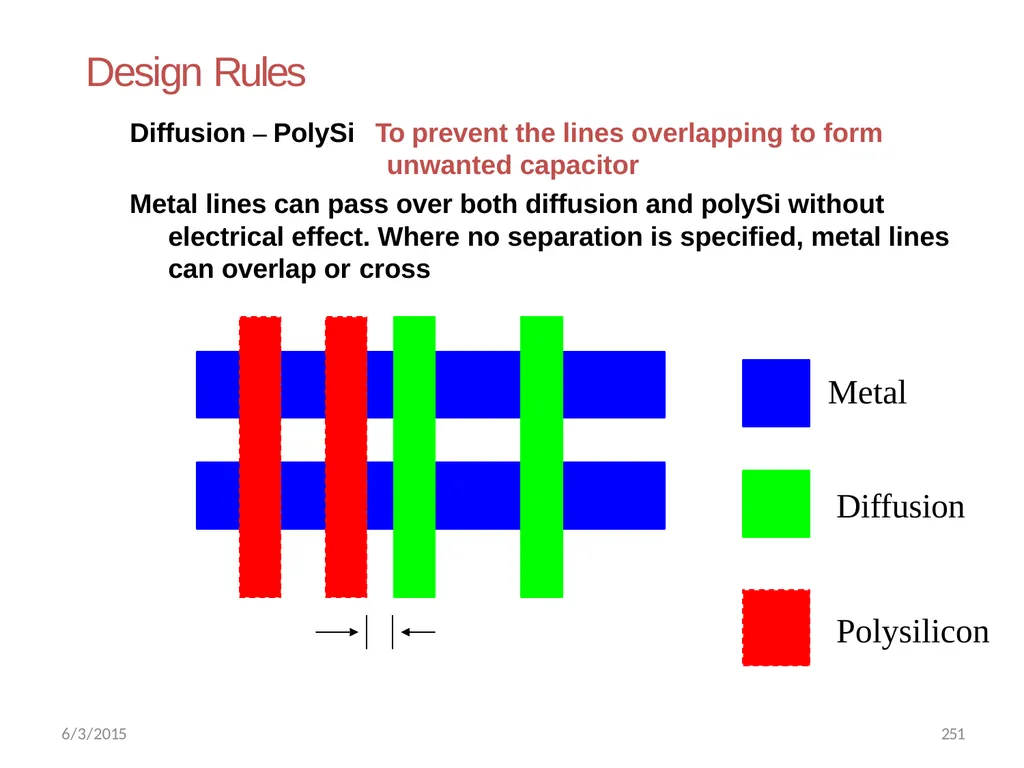
Design Rules Diffusion – PolySi To prevent the lines overlapping to form unwanted capacitor
Metal lines can pass over both diffusion and polySi without electrical effect. Where no separation is specified, metal lines can overlap or cross Metal
Diffusion Polysilicon 6/3/2015 251<br>
Metal lines can pass over both diffusion and polySi without electrical effect. Where no separation is specified, metal lines can overlap or cross Metal
Diffusion Polysilicon 6/3/2015 251<br>
89
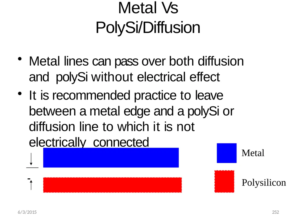
Metal Vs PolySi/Diffusion Metal lines can pass over both diffusion and polySi without electrical effect
It is recommended practice to leave between a metal edge and a polySi or diffusion line to which it is not electrically connected Metal 6/3/2015 252 Polysilicon<br>
It is recommended practice to leave between a metal edge and a polySi or diffusion line to which it is not electrically connected Metal 6/3/2015 252 Polysilicon<br>
90
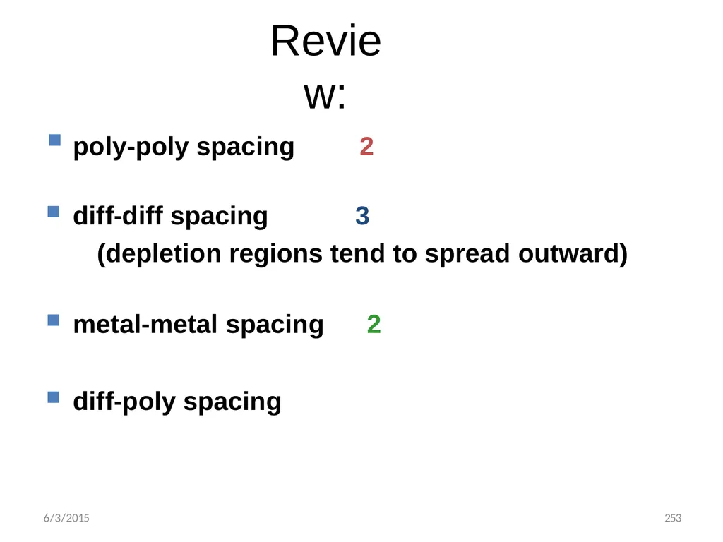
6/3/2015 253 poly-poly spacing 2
diff-diff spacing 3
(depletion regions tend to spread outward)
metal-metal spacing 2
diff-poly spacing Review:<br>
diff-diff spacing 3
(depletion regions tend to spread outward)
metal-metal spacing 2
diff-poly spacing Review:<br>
91
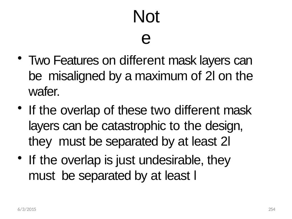
6/3/2015 254 Note Two Features on different mask layers can be misaligned by a maximum of 2l on the wafer.
If the overlap of these two different mask layers can be catastrophic to the design, they must be separated by at least 2l
If the overlap is just undesirable, they must be separated by at least l<br>
If the overlap of these two different mask layers can be catastrophic to the design, they must be separated by at least 2l
If the overlap is just undesirable, they must be separated by at least l<br>
92
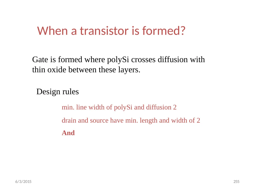
6/3/2015 255 When a transistor is formed? Gate is formed where polySi crosses diffusion with
thin oxide between these layers.
Design rules
min. line width of polySi and diffusion 2
drain and source have min. length and width of 2
And<br>
thin oxide between these layers.
Design rules
min. line width of polySi and diffusion 2
drain and source have min. length and width of 2
And<br>
93
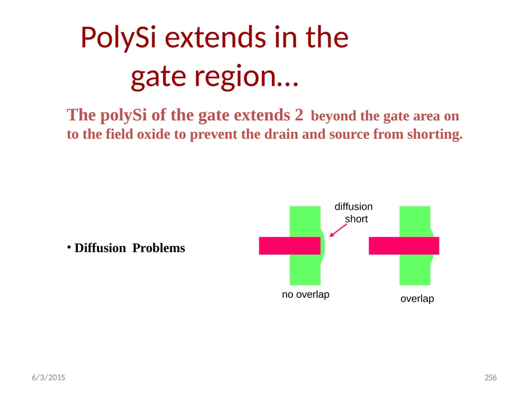
The polySi of the gate extends 2 beyond the gate area on
to the field oxide to prevent the drain and source from shorting. no overlap 6/3/2015 256 overlap diffusion short Diffusion Problems PolySi extends in the gate region…<br>
to the field oxide to prevent the drain and source from shorting. no overlap 6/3/2015 256 overlap diffusion short Diffusion Problems PolySi extends in the gate region…<br>
94
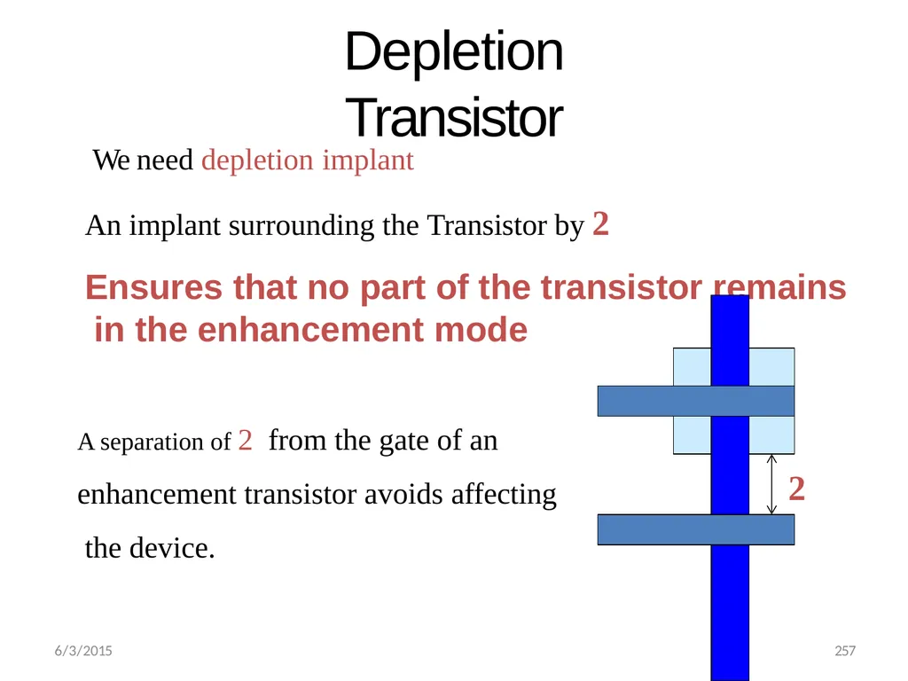
Depletion Transistor We need depletion implant
An implant surrounding the Transistor by 2
Ensures that no part of the transistor remains in the enhancement mode A separation of 2 from the gate of an enhancement transistor avoids affecting the device. 2 6/3/2015 257<br>
An implant surrounding the Transistor by 2
Ensures that no part of the transistor remains in the enhancement mode A separation of 2 from the gate of an enhancement transistor avoids affecting the device. 2 6/3/2015 257<br>
95
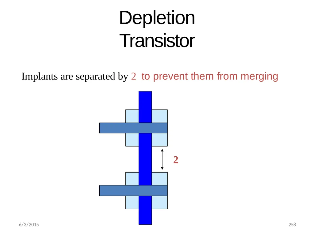
Depletion Transistor Implants are separated by 2 to prevent them from merging 2 6/3/2015 258<br>
96
6/3/2015 259 Butting Contact The gate and source of a depletion device can be connected by a method known as butting contact. Here metal makes contact to both the diffusion forming the source of the depletion transistor and to the polySi forming this device’s gate.
Advantage:
No buried contact mask required and avoids associated processing.<br>
Advantage:
No buried contact mask required and avoids associated processing.<br>
97
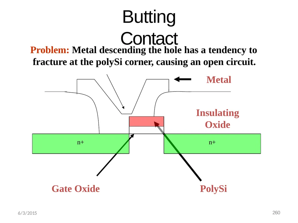
Butting Contact n+ n+ Gate Oxide PolySi Problem: Metal descending the hole has a tendency to fracture at the polySi corner, causing an open circuit.
Metal
Insulating
Oxide 6/3/2015 260<br>
Metal
Insulating
Oxide 6/3/2015 260<br>
98
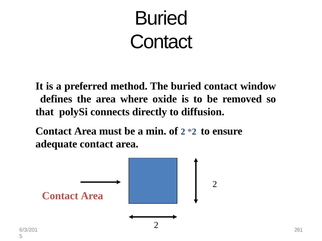
Buried Contact It is a preferred method. The buried contact window defines the area where oxide is to be removed so that polySi connects directly to diffusion.
Contact Area must be a min. of 2*2 to ensure adequate contact area. 2 Contact Area
2 6/3/2015 261<br>
Contact Area must be a min. of 2*2 to ensure adequate contact area. 2 Contact Area
2 6/3/2015 261<br>
99
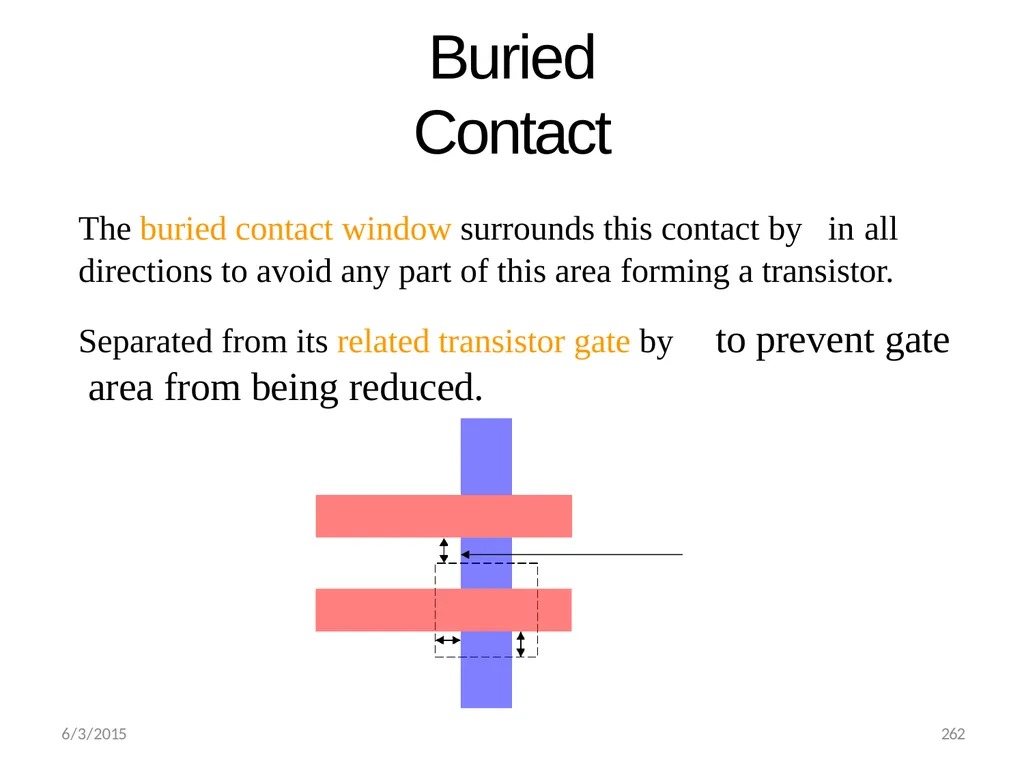
Buried Contact The buried contact window surrounds this contact by in all
directions to avoid any part of this area forming a transistor.
Separated from its related transistor gate by to prevent gate area from being reduced. 6/3/2015 262<br>
directions to avoid any part of this area forming a transistor.
Separated from its related transistor gate by to prevent gate area from being reduced. 6/3/2015 262<br>
100
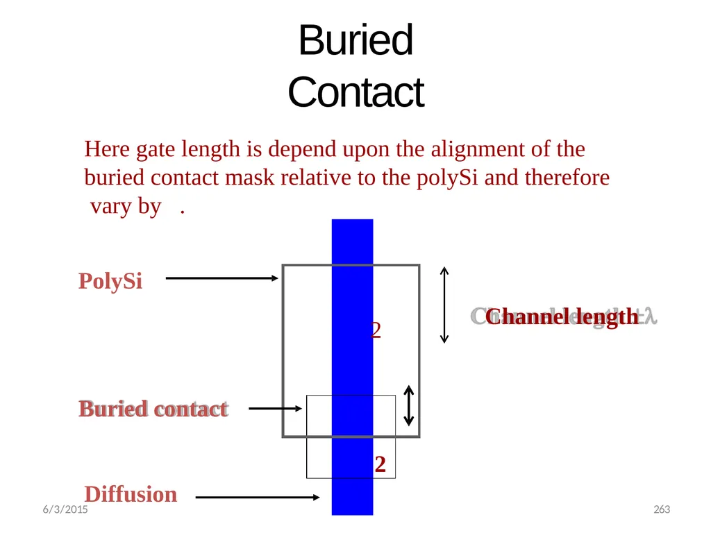
Buried Contact Here gate length is depend upon the alignment of the buried contact mask relative to the polySi and therefore vary by .
PolySi
Channel length
Buried contact Diffusion 6/3/2015 263<br>
PolySi
Channel length
Buried contact Diffusion 6/3/2015 263<br>
101
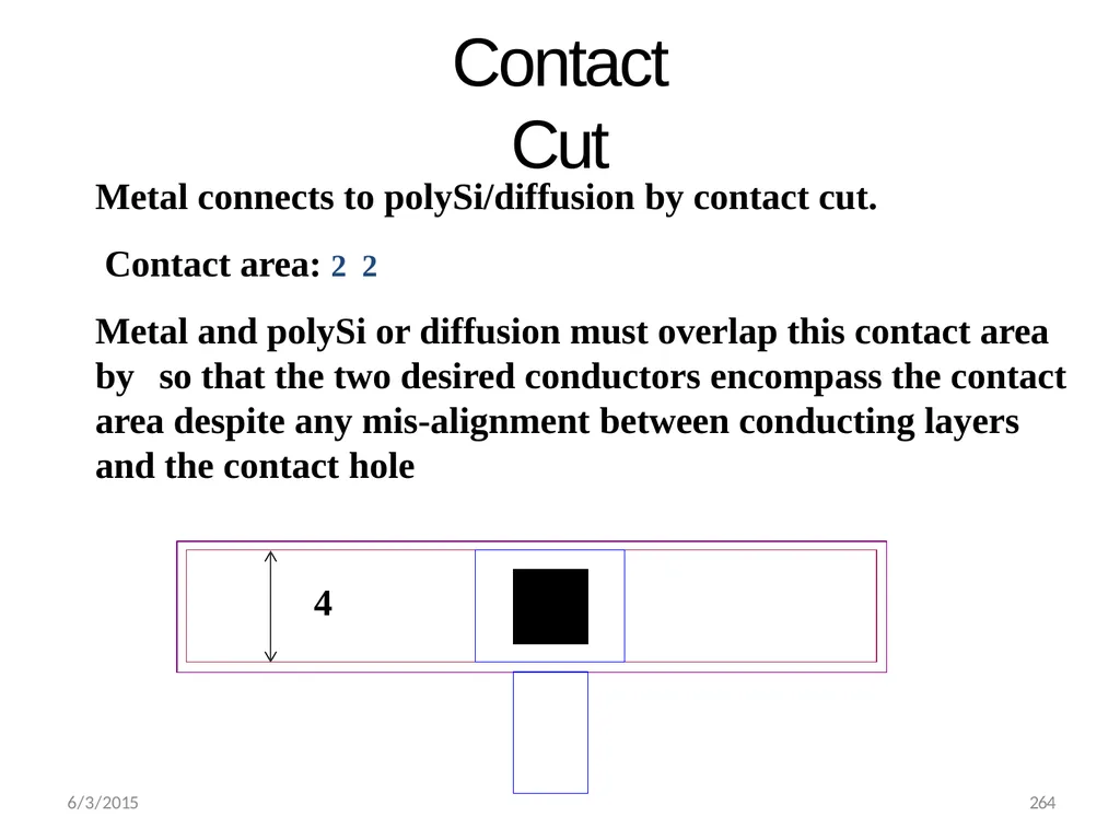
Contact Cut Metal connects to polySi/diffusion by contact cut. Contact area: 22
Metal and polySi or diffusion must overlap this contact area by so that the two desired conductors encompass the contact area despite any mis-alignment between conducting layers and the contact hole 6/3/2015 264<br>
Metal and polySi or diffusion must overlap this contact area by so that the two desired conductors encompass the contact area despite any mis-alignment between conducting layers and the contact hole 6/3/2015 264<br>
102
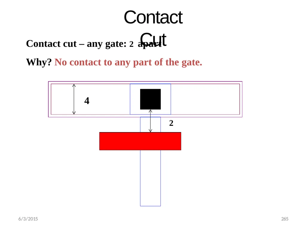
Contact Cut Contact cut – any gate: 2 apart
Why? No contact to any part of the gate.
4
2 6/3/2015 265<br>
Why? No contact to any part of the gate.
4
2 6/3/2015 265<br>
103
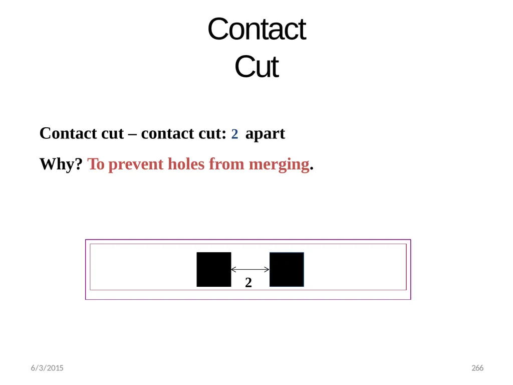
Contact Cut Contact cut – contact cut: 2 apart Why? To prevent holes from merging. 2 6/3/2015 266<br>
104
6/3/2015 267 Rules for CMOS layout Similar to those for NMOS except No
Depletion implant
Buried contact
Additional rules
Definition of n-well area
Threshold implant of two types of transistor
Definition of source and drains regions for the NMOS and PMOS.<br>
Depletion implant
Buried contact
Additional rules
Definition of n-well area
Threshold implant of two types of transistor
Definition of source and drains regions for the NMOS and PMOS.<br>
105
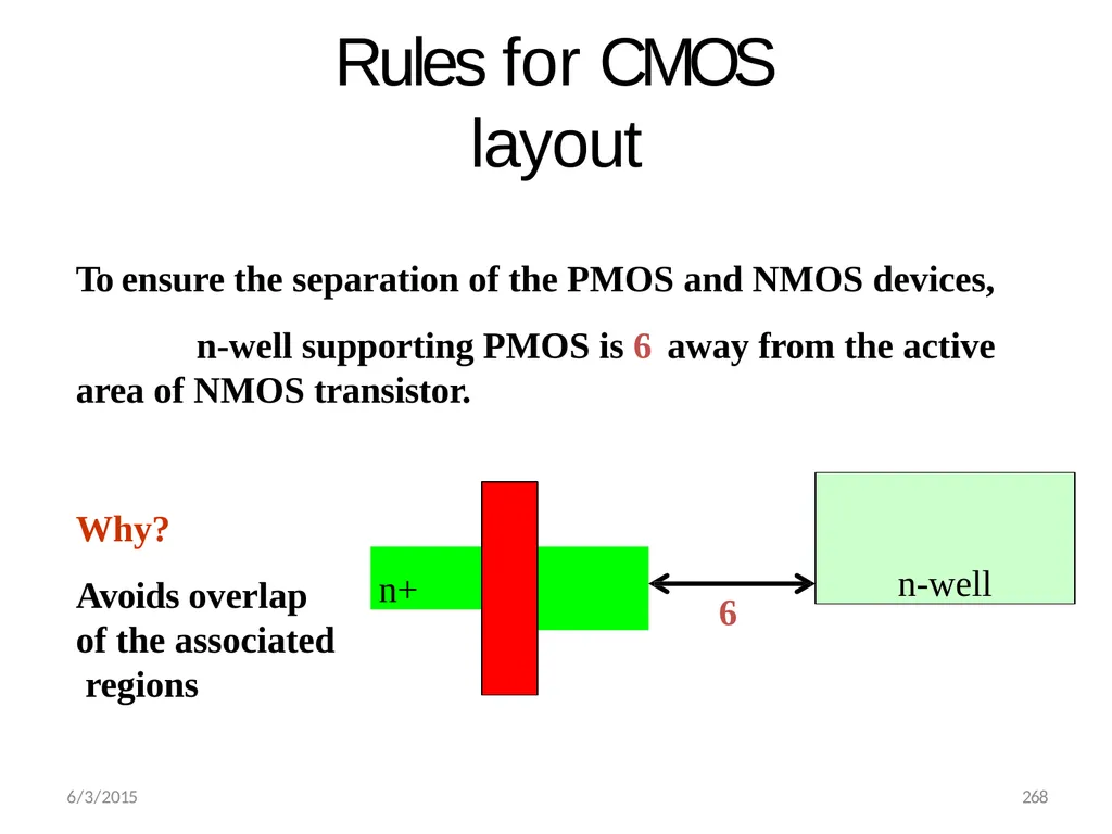
Rules for CMOS layout To ensure the separation of the PMOS and NMOS devices, n-well supporting PMOS is 6 away from the active
area of NMOS transistor. Why?
Avoids overlap of the associated regions n-well n+ 6 6/3/2015 268<br>
area of NMOS transistor. Why?
Avoids overlap of the associated regions n-well n+ 6 6/3/2015 268<br>
106
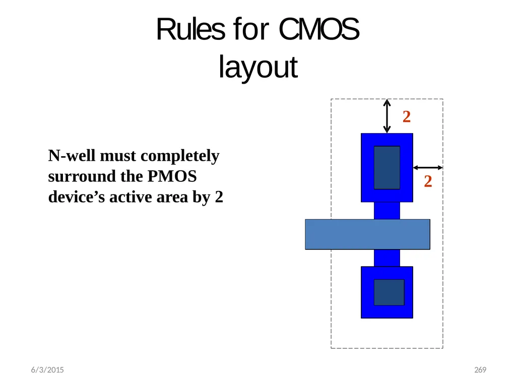
Rules for CMOS layout 2 6/3/2015 269 2 N-well must completely surround the PMOS device’s active area by 2<br>
107
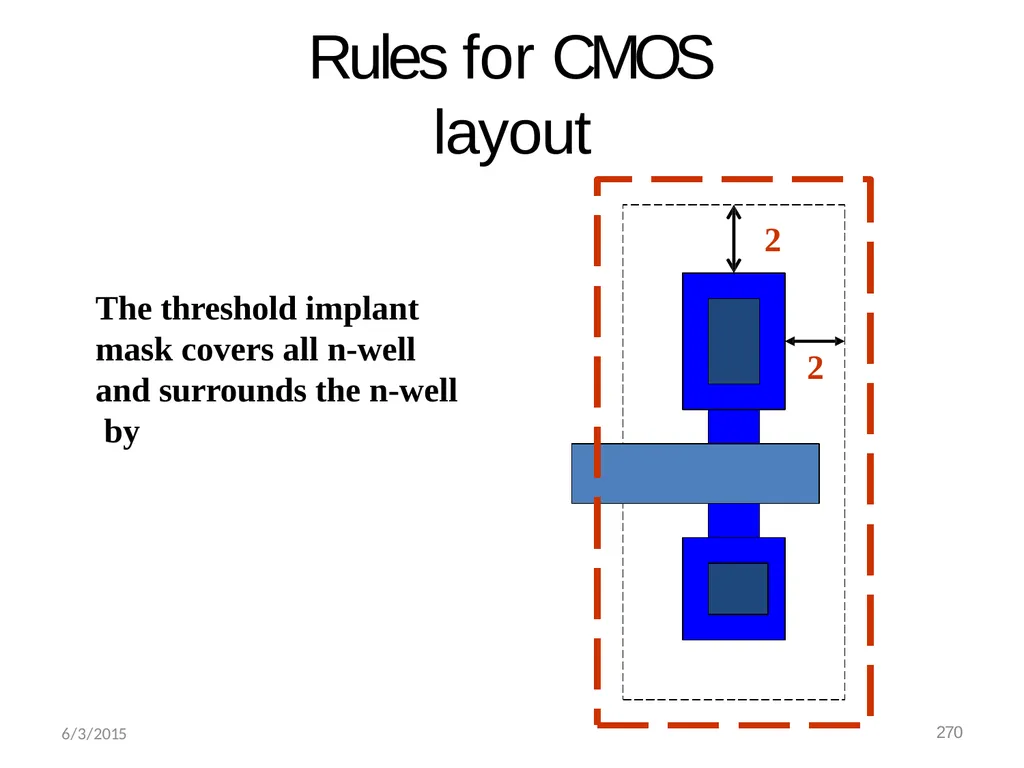
Rules for CMOS layout 2 2 The threshold implant mask covers all n-well and surrounds the n-well by 6/3/2015 270<br>
108
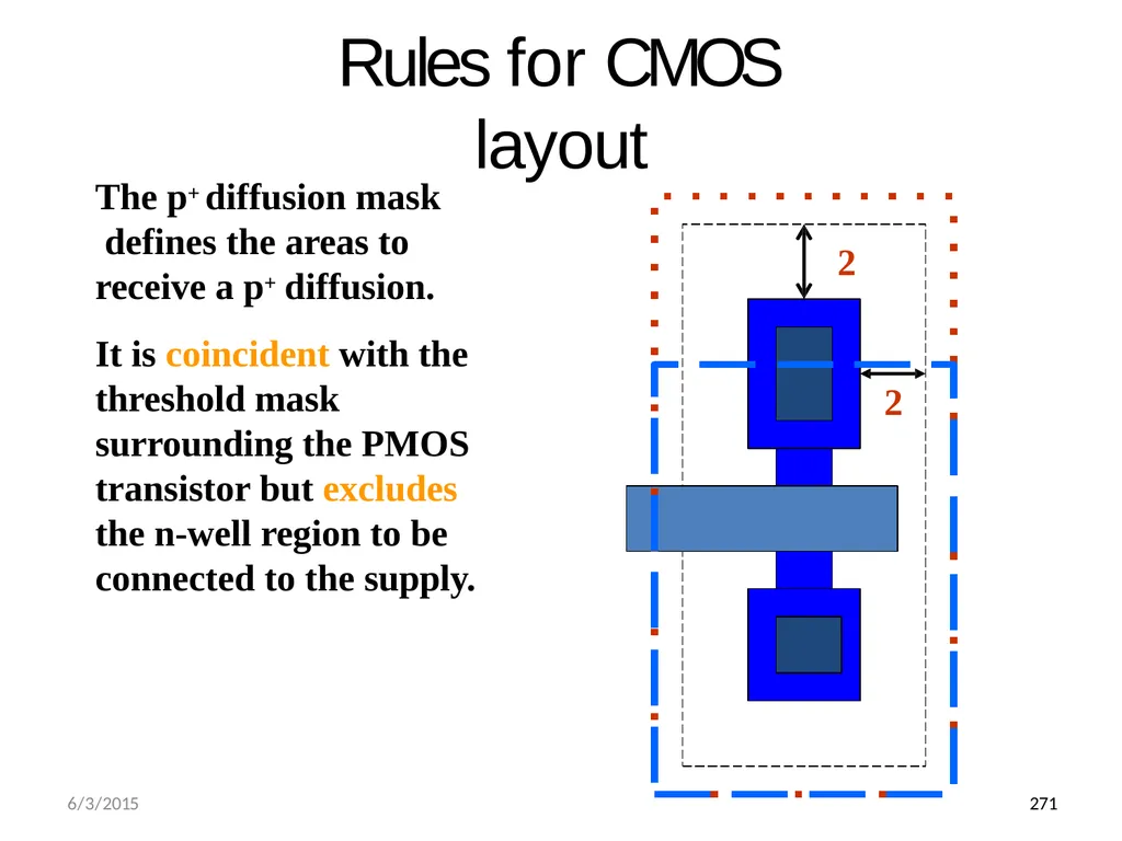
Rules for CMOS layout 2 2 The p+ diffusion mask defines the areas to receive a p+ diffusion.
It is coincident with the threshold mask surrounding the PMOS transistor but excludes the n-well region to be connected to the supply. 6/3/2015 271<br>
It is coincident with the threshold mask surrounding the PMOS transistor but excludes the n-well region to be connected to the supply. 6/3/2015 271<br>
109
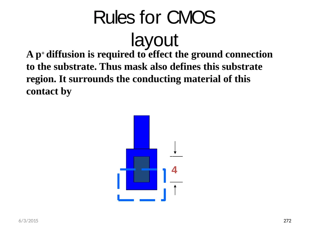
Rules for CMOS layout A p+ diffusion is required to effect the ground connection to the substrate. Thus mask also defines this substrate region. It surrounds the conducting material of this contact by 4 6/3/2015 272<br>
110
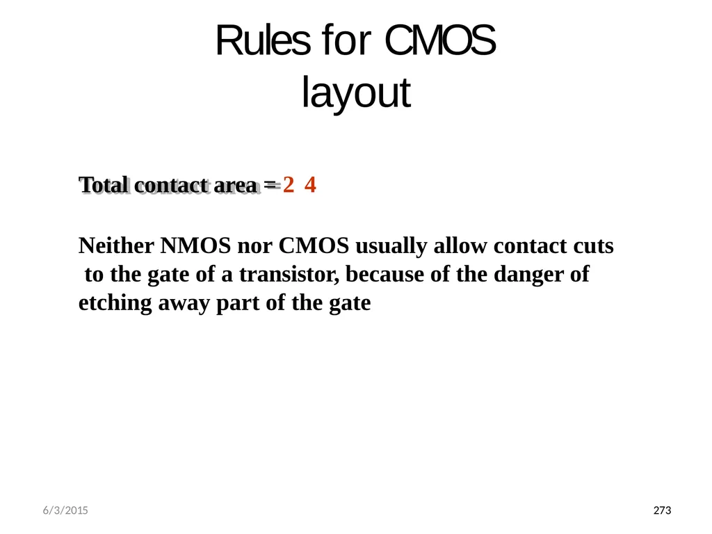
Rules for CMOS layout Total contact area = 24
Neither NMOS nor CMOS usually allow contact cuts to the gate of a transistor, because of the danger of etching away part of the gate 6/3/2015 273<br>
Neither NMOS nor CMOS usually allow contact cuts to the gate of a transistor, because of the danger of etching away part of the gate 6/3/2015 273<br>