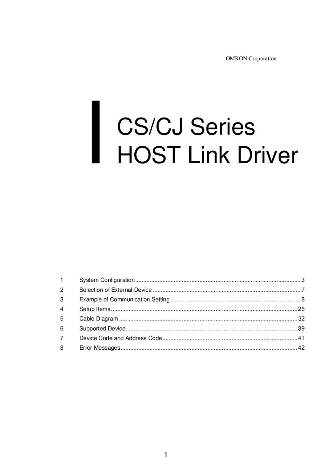
/
CSCJ Series HOST Link Driver    GPPro EX DevicePLC Connection Manua CSCJ Series HOST Link Driver    GPPro EX DevicePLC Connection Manua

CSCJ Series HOST Link Driver GPPro EX DevicePLC Connection Manua - PDF document

wang
wang . @wang
Follow
344 views
Uploaded On 2021-09-22

CSCJ Series HOST Link Driver GPPro EX DevicePLC Connection Manua - PPT Presentation

This manual describes how to connect the Display and the External Device target PLCIn this manual the connection procedure will be described by following the below sections1System ConfigurationThis se ID: 882850

external device connection set device external set connection pro setting link plc manual display switch settings series host network

Share:

Link:

Embed:

Download Presentation from below link

Download Pdf The PPT/PDF document "CSCJ Series HOST Link Driver GPPro EX..." is the property of its rightful owner. Permission is granted to download and print the materials on this web site for personal, non-commercial use only, and to display it on your personal computer provided you do not modify the materials and that you retain all copyright notices contained in the materials. By downloading content from our website, you accept the terms of this agreement.


Presentation Transcript

1 CS/CJ Series HOST Link Driver GP-Pro
CS/CJ Series HOST Link Driver GP-Pro EX Device/PLC Connection Manual This manual describes how to connect the Display and the External Device (target PLC).In this manual, the connection procedure will be described by following the below sections: 1 System ConfigurationThis section shows the types of External Devices which can be connected and SIO type. "1 System Configurati

2 on" (page 3) 2 Selection of External Dev
on" (page 3) 2 Selection of External DeviceSelect a model (series) of the External Device to be connected and connection method. "2 Selection of External Device" (page 7) 3 Example of Communication SettingsThis section shows setting examples for communicating between the Display and the External Device. "3 Example of Communication Setting" (page 8) 4 Communication SettingsThis

3 section describes communication setup i
section describes communication setup items on the Display.Set communication settings of the Display with GP-Pro EX or in off-line mode. "4 Setup Items" (page 26) 5 Cable DiagramThis section shows cables and adapters for connecting the Display and the External Device. "5 Cable Diagram" (page 32) Operation CS/CJ Series HOST Link Driver GP-Pro EX Device/PLC Connection Manual

4 Connection Configuration• 1:1 Connectio
Connection Configuration• 1:1 Connection•1:n Connection•Access beyond networkYou can access beyond maximum 3 levels of network. DisplayExternalDevice ExternalDeviceExternalDeviceMax 16 units (for RS422/485 connection) Network 1Network 3 CS/CJ Series HOST Link Driver GP-Pro EX Device/PLC Connection Manual DIP switch setting: RS-422/485 (4 wire)DIP switch setting: RS-422/485

5 (2 wire) DIP switch Setting Description
(2 wire) DIP switch Setting Description1OFFReserved (always OFF)2ONSIO type: RS-422/4853ON4OFFOutput mode of SD (TXD) data: Always output5OFFTerminal resistance (220) insertion to SD (TXD): None6OFFTerminal resistance (220) insertion to RD (RXD): None7OFFShort-circuit of SDA (TXA) and RDA (RXA): Not available8OFFShort-circuit of SDB (TXB) and RDB (RXB): Not available9OFFRS

6 (RTS) Auto control mode: Disabled10OFF D
(RTS) Auto control mode: Disabled10OFF DIP switch Setting Description1OFFReserved (always OFF)2ONSIO type: RS-422/4853ON4OFFOutput mode of SD (TXD) data: Always output5OFFTerminal resistance (220) insertion to SD (TXD): None6OFFTerminal resistance (220) insertion to RD (RXD): None7ONShort-circuit of SDA (TXA) and RDA (RXA): Available8ONShort-circuit of SDB (TXB) and RDB (RXB

7 ): Available9ONRS (RTS) Auto control mo
): Available9ONRS (RTS) Auto control mode: Enabled10ON CS/CJ Series HOST Link Driver GP-Pro EX Device/PLC Connection Manual 2Selection of External DeviceSelect the External Device to be connected to the Display. Setup Items Setup DescriptionSelect the maker of the External Device to be connected. Select "OMRON Corporation".Select a model (series) of the External Device to

8 be connected and connection method. Sele
be connected and connection method. Select "CS/CJ Series HOST Link".Check the External Device which can be connected in "CS/CJ Series HOST Link" in system configuration."1 System Configuration" (page 3)Check this option when you synchronize the system data area of Display and the device (memory) of External Device. When synchronized, you can use the ladder program of External

9 Device to switch the display or display
Device to switch the display or display the window on the display.Cf.GP-Pro EX Reference Manual "Appendix 1.4 LS Area (Direct Access This can be also set with GP-Pro EX or in off-line mode of Display.Cf.GP-Pro EX Reference Manual " 5.17.6 Setting Guide of [System Setting Window][Main Unit Settings] Settings GuideSystem Area Setting"Cf.Maintenance/Troubleshooting "2.15.1 Settin

10 gs common to all Display System Area Se
gs common to all Display System Area Settings"Select the Display port to be connected to the External Device. CS/CJ Series HOST Link Driver GP-Pro EX Device/PLC Connection Manual To display the setting screen, click ([Setting]) of External Device you want to set from [Device-Specific Settings] of [Device/PLC Settings].When you connect multiple External Device, click from

11 [Device-Spec •Set the unit No. you set i
[Device-Spec •Set the unit No. you set in the External Device for "Unit No.".•If you do not access beyond network, set "0" for "Network" and "Node" settings. CS/CJ Series HOST Link Driver GP-Pro EX Device/PLC Connection Manual 3.2Setting Example 2Communication SettingsTo display the setting screen, select [Device/PLC Settings] from [System setting window] in workspace. CS/

12 CJ Series HOST Link Driver GP-Pro EX
CJ Series HOST Link Driver GP-Pro EX Device/PLC Connection Manual Setting of External DeviceClick the [Peripheral Port] tab from the [PC System Settings] of thsettings of the peripheral port and set as below.•Do not set the duplicate node address in the same network address group. Setup Items SpeedHOST link*1Use the DIP switch on the front of the unit for setting.SW4: ONUni

13 t No.Source Network Address*2Parameter u
t No.Source Network Address*2Parameter used when you access beyond network. Set in the routing table of "CX-Net Network Configuration". Please refer to the manual of the External Device for more details.Node Address Setting Rotary Switch*3Parameter used when you access beyond network. Set with the rotary switch on the front of the Controller Link u

14 nit used for access beyond network. CS/
nit used for access beyond network. CS/CJ Series HOST Link Driver GP-Pro EX Device/PLC Connection Manual To display the setting screen, click ([Setting]) of External Device you want to set from [Device-Specific Settings] of [Device/PLC Settings].When you connect multiple External Device, click from [Device-Spec •Set the unit No. you set in the External Device for "Unit N

15 o.".•If you do not access beyond network
o.".•If you do not access beyond network, set "0" for "Network" and "Node" settings. CS/CJ Series HOST Link Driver GP-Pro EX Device/PLC Connection Manual 3.4Setting Example 4Communication SettingsTo display the setting screen, select [Device/PLC Settings] from [System setting window] in workspace. CS/CJ Series HOST Link Driver GP-Pro EX Device/PLC Connection Manual Sett

16 ing of External DeviceFor communication
ing of External DeviceFor communication settings of INNER board, open [I/O Table] of the ladder software first. Then, select [INNER Board Soft Switch] from the menu displayed by right-clicking [CS**-CPU**] (CPU of the External Device to set) and set as below.•Do not set the duplicate node address in the same network address group. Setup Items WIRE (2wire/4wire switch)*1Use the

17 WIRE switch on the front of the INNER b
WIRE switch on the front of the INNER board to set.TERM (Termination resistance switch)*2Use the TERM switch on the front of the INNER board to set. For 1:n connection, set only the station that serves as termination resistance to ON.Port settings*3[Port settings] can be set only when the ladder software you use is a CX-One.User settingsLine SpeedDefault (

18 HOST Link)Send Delay TimeUnit No.Source
HOST Link)Send Delay TimeUnit No.Source Network Address*4Parameter used when you access beyond network. Set in the routing table of "CX-Net Network Configuration". Please refer to the manual of the External Device for more details.Node Address Setting Rotary Switch*5Parameter used when you access beyond network. Set with the rotary switch on the front of the Cont

19 roller Link unit used for
roller Link unit used for access beyond network. CS/CJ Series HOST Link Driver GP-Pro EX Device/PLC Connection Manual To display the setting screen, click ([Setting]) of External Device you want to set from [Device-Specific Settings] of [Device/PLC Settings].When you connect multiple External Device, click from [Device-Spec •Set the unit No. you set in the

20 External Device for "Unit No.".•If you d
External Device for "Unit No.".•If you do not access beyond network, set "0" for "Network" and "Node" settings. CS/CJ Series HOST Link Driver GP-Pro EX Device/PLC Connection Manual 3.6Setting Example 6Communication SettingsTo display the setting screen, select [Device/PLC Settings] from [System setting window] in workspace. CS/CJ Series HOST Link Driver GP-Pro EX Device

21 /PLC Connection Manual Setting of Extern
/PLC Connection Manual Setting of External DeviceFor communication settings of the comm register the serial communication unit to be used by the ladder software in advance.After registration, open [I/O Table] of the ladder software. Click [Switch] from the menu displayed by right-clicking [Serial Communication Unit] and set as below.•Do not set the duplicate node address in th

22 e same network address group. Setup Item
e same network address group. Setup Items WIRE (2wire/4wire switch)*1Use the WIRE switch on the front of the Controller Link unit to set.TERM (Termination resistance switch)*2Use the TERM switch on the front of the Controller Link unit to set. For 1:n connection, set only the station that serves as termination resistance to ON.Port settings*3[Port settings]

23 can be set only when the ladder softwar
can be set only when the ladder software you use is a CX-One.User settingsLine SpeedDefault (HOST Link)Send Delay TimeUnit No. Setting Rotary Switch*4You need to set this switch to the same value as "CPU High Function Unit No." of the serial communication unit in the I/O table assigned by the ladder tool.Same value as "CPU High Function Unit No."Unit No.Sour

24 ce Network Address*5Parameter used when
ce Network Address*5Parameter used when you access beyond network. Set in the routing table of "CX-Net Network Configuration". Please refer to the manual of the External Device for more details.Node Address Setting Rotary Switch*6Parameter used when you access beyond network. Set with the rotary switch on the front of the Controller Link unit used

25 for access beyond network. CS/CJ Series
for access beyond network. CS/CJ Series HOST Link Driver GP-Pro EX Device/PLC Connection Manual 4Setup ItemsSet communication settings of the Display with GP-Pro EX or in off-line mode of the Display.The setting of each parameter must be identical to that of External Device."3 Example of Communication Setting" (page 8)4.1Setup Items in GP-Pro EXCommunication SettingsTo dis

26 play the setting screen, select [Device/
play the setting screen, select [Device/PLC Settings] from [System setting window] in workspace. Setup Items Setup DescriptionSIO TypeSelect the SIO type to communicate with the External Device.SpeedSelect speed between the External Device and the Display.Data LengthSelect how to check parity.Stop BitFlow ControlSelect the communication control method to prevent overflow of tr

27 ansmission and reception data.TimeoutUse
ansmission and reception data.TimeoutUse an integer from 1 to 127 to enter the time (sec) for which the Display waits for the response from the External Device.In case of no response from the External Device, use an integer from 0 to 255 to enter how many times the Display retransmits the command.continued to next page CS/CJ Series HOST Link Driver GP-Pro EX Device/PLC C

28 onnection Manual To display the setting
onnection Manual To display the setting screen, click ([Setting]) of External Device you want to set from [Device-Specific Settings] of [Device/PLC Settings].When you connect multiple External Device, click from [Device-Specice-SpecSettings] to add another External Device.Wait To SendUse an integer from 0 to 255 to enter standby time (ms) for the Display from receiving You c

29 an switch RI/VCC of the 9th pin when you
an switch RI/VCC of the 9th pin when you select RS232C for SIO type.It is necessary to change RI/5V by changeover switch of IPC when connect with IPC. Please refer to the manual of the IPC for more detail. Setup Items Setup DescriptionUnit No.Enter the unit No. for HOST link.Enter the destination network address.NodeEnter the destination node address. Setup Items Setup Descrip

30 tion CS/CJ Series HOST Link Driver GP
tion CS/CJ Series HOST Link Driver GP-Pro EX Device/PLC Connection Manual Wait To SendUse an integer from 0 to 255 to enter standby time (ms) for the Display from receiving packets to transmitting next commands. Setup Items Setup Description CS/CJ Series HOST Link Driver GP-Pro EX Device/PLC Connection Manual To display the setting screen, touch [Device/PLC Settings] fro

31 m [Peripheral Settings]. Touch the Exter
m [Peripheral Settings]. Touch the External Device you want to set from the displayed list, and touch [Option]. Setup Items Setup DescriptionYou can switch RI/VCC of the 9th pin when you select RS232C for SIO type.It is necessary to change RI/5V by changeover switch of IPC when connect with IPC. Please refer to the manual of the IPC for more detail. CS/CJ Series HOST Link Driv

32 er GP-Pro EX Device/PLC Connection Ma
er GP-Pro EX Device/PLC Connection Manual 5Cable DiagramThe cable diagram shown below may be different from the cable diagram recommended by OMRON Corporation. Please be assured there is no operational problem in applying the cable diagram shown in this •The FG pin of the main body of the External Device must be D-class grto the manual of the External Device for more detail

33 s.•SG and FG are connected inside the Di
s.•SG and FG are connected inside the Display. When connecting SG to the External Device, design the system not to form short-circuit loop.•Connect the isolation unit, when communication is not stabilized under the influence of a noise etc.Cable Diagram 1A) When using OMRON SYSMAC link cable (CA3-CBLSYS-01) by Pro-faceB) When using XW2Z-200S-V or XW2Z-500S-V by OMRON Corporati

34 onC) When using your own cable (Connecti
onC) When using your own cable (Connection Port) Cable GP (COM1)ST (COM1)PC/AT*1Only the COM port which can communicate by RS-232C can be used. IPC COM Port (page 5)OMRON SYSMAC link cable by Pro-faceCA3-CBLSYS-01 (5m)XW2Z-200S-V (2m) or XW2Z-500S-V (5m) by OMRON Corporation CYour own cableThe cable length must be 15m or less. DisplayExternalDeviceCA3-CBLSYS-01orXW2Z-200S-Vor

35 XW2Z-500S-V DisplayD-sub 9 pin (socket)P
XW2Z-500S-V DisplayD-sub 9 pin (socket)PinSignalnameShieldExternal DeviceD-sub 9 pin (plug) PinSignalnameSDRDRSSG3223SDRDRSSGFG CS/CJ Series HOST Link Driver GP-Pro EX Device/PLC Connection Manual Cable Diagram 2A) When using CS1W-CN225 or CS1W-CN625 by OMRON Corporation or your own cableB) When using CS1W-CN226 or CS1W-CN626 by OMRON Corporation or your own cable (Connecti

36 on Port) Cable GP (COM1)ST (COM1)PC/AT*
on Port) Cable GP (COM1)ST (COM1)PC/AT*1Only the COM port which can communicate by RS-232C can be used. IPC COM Port (page 5)CS1W-CN225 (2m) or CS1W-CN625 (6m) by OMRON Corporation Your own cableThe cable length must be 15m or less.CS1W-CN226 (2m) or CS1W-CN626 (6m) by OMRON Corporation Your own cable Your own cableCS1W-CN225CS1W-CN625 Your own cableCS1W-CN226CS1W-CN626 CS/CJ

37 Series HOST Link Driver GP-Pro EX De
Series HOST Link Driver GP-Pro EX Device/PLC Connection Manual Cable Diagram 3 Display(Connection Port) Cable (COM1)AGP-3302B (COM2) (COM2)*1All GP models except AGP-3302B*2All ST models except AST-3211A*3Only the COM port which can communicate by RS-422/485 (4 wire) can be used. IPC COM Port (page 5)COM port conversion adapter by Pro-faceCA3-ADPCOM-01Connector terminal b

38 lock conversion adapter by Pro-faceCA3-A
lock conversion adapter by Pro-faceCA3-ADPTRM-01Your own cableThe cable length must be 500m or less.BYour own cable (COM2)*4All GP models except GP-3200 series and AGP-3302BOnline adapter by Pro-faceCA4-ADPONL-01Connector terminal block conversion adapter by Pro-faceCA3-ADPTRM-0Your own cableOnline adapter by Pro-faceCA4-ADPONL-01Your own cable •Please turn ON the termination

39 resistance switch on the PLC.•Set the 2w
resistance switch on the PLC.•Set the 2wire/4wire toggle switch to 4wire.•Note that pole A and pole B are reversely named for the Display and the External Device. CS/CJ Series HOST Link Driver GP-Pro EX Device/PLC Connection Manual B) When using your own cable•1:1 connection•1:n connection •When the display unit you use is an IPC, turn ON the DIP switch 6 to insert the term

40 ination resistance. Termination Terminat
ination resistance. Termination Termination CS/CJ Series HOST Link Driver GP-Pro EX Device/PLC Connection Manual D) When using the online adapter (CA4-ADPONL-01) by Pro-face and your own cable•1:1 connection•1:n connection Your own cableTermination Your own cableTermination CS/CJ Series HOST Link Driver GP-Pro EX Device/PLC Connection Manual 7Device Code and Address Code

41 Use device code and address code when yo
Use device code and address code when you select "Device & Address" for Device Device Name Device Code (HEX) Channel I/O-0080Word AddressInternal Auxiliary RelayW0082Word AddressSpecial Auxiliary RelayA0085Word AddressLatch RelayH0084Word AddressTimer (Current Value)T0060Word AddressCounter (Current Value)C0061Word AddressData MemoryD0000Word AddressExtension Data MemoryE0001

42 0Word AddressE10011Word AddressE20012Wor
0Word AddressE10011Word AddressE20012Word AddressE30013Word AddressE40014Word AddressE50015Word AddressE60016Word AddressE70017Word AddressE80018Word AddressE90019Word AddressEA001AWord AddressEB001BWord AddressEC001CWord AddressExtension Data Memory(Current Bank)EM0001Word AddressTask Flag(Status)TK0002Word AddressIndex RegisterIR0003Word AddressData RegisterDR0004Word Addres