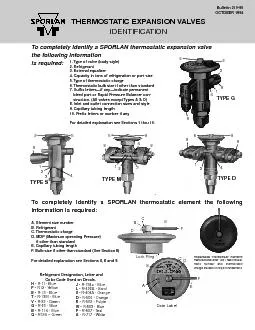
/
To completely identify a SPORLAN thermostatic expansion valve the foll To completely identify a SPORLAN thermostatic expansion valve the foll

To completely identify a SPORLAN thermostatic expansion valve the foll - PDF document

white
white . @white
Follow
362 views
Uploaded On 2021-06-19

To completely identify a SPORLAN thermostatic expansion valve the foll - PPT Presentation

Element size numberRefrigerantThermostatic chageMOP MaxiCapillary tubing lengthBulb size if other than standaRefrigerant Designation manu 5 8 4 1 8 2 9 4 2 1 8 8 9 5 8 1 2 3 8 4 9 5 4 3 2 1 8 8 5 9FE ID: 845431

ext 151 push odf 151 ext odf push rod 161 external sae seal kits flare flange 643 2int types

Share:

Link:

Embed:

Download Presentation from below link

Download Pdf The PPT/PDF document "To completely identify a SPORLAN thermos..." is the property of its rightful owner. Permission is granted to download and print the materials on this web site for personal, non-commercial use only, and to display it on your personal computer provided you do not modify the materials and that you retain all copyright notices contained in the materials. By downloading content from our website, you accept the terms of this agreement.


Presentation Transcript

1 To completely identify a SPORLAN thermos
To completely identify a SPORLAN thermostatic expansion valve the following informationo complete Element size numberRefrigerantThermostatic chageMOP (MaxiCapillary tubing lengthBulb size if other than standaRefrigerant Designation manu 5 8 4 1 8 2 9 4 2 1 8 8 9 5 8 1 2 3 8 4 9 5 4 3 2 1 8 8 5 9FECBDEFFABCD Lock Ring Date Label TACP, Z, ZP, VGA, and X are generally applied in the rangeTAe essentially the samecharactele diaphragm r igerants in most of our element sialve ypeNominal CapaciRating (R-717)e n)Dischargeube Orifice (in)1/161/321/161/167/645/643/167/643/165/325/161/85/165/323/83/163/87/16 FCP60FCFZ, FZPVCP100, GAVCVZ, VZP40VXJCXCLCLZ, LZPLXSZ, SZPSXRZ, RZPRXPCPZ, PZPPX Page 2 — Bulletin 210-60 Valve Types (STANDARD)BF SAE FlareC SAE FlareD FPT or Socket WeldEBFExtended ODF SolderEBS Extended ODF SolderF SAE Flare G SAE FlareEG ODF SolderH ODF Solder Flange M ODF Solder Flange Nl SAEFlare O ODF SolderP ODF Solder RIVESAE Flare or ODF SolderS ODF SolderSBFExtended ODF SolderV ODF Solder FlangeW ODF Solder FlangeA FPI or Socket WeldValve Types (OEM)Bl SAE Flare or ODF SolderFB SAE Flare or ODF SolderK ODF SolderI SAE Flare or ODF SolderX S

2 AE Flare or ODF Solder R-12 R-13 R-13B1
AE Flare or ODF Solder R-12 R-13 R-13B1 R-23 R-114-BlueR-124 R-134a R-402A R-404A R-500 R-502 R-503 R-507 R-717-White TABLE-B — DISCHARGE TUBE & PORT SIZESREFRIGERANTEXTREME TEM-PERATUREREFRIGERATION-40°F.to -100°F.LOW TEMPERATUREREFRIGERATION0°F.to -40°F.COMMERCIALREFRIGERATION+50°F.to -10°F.AIR CONDITIONINGORHEAT PUMP y Range8 8 1/2 3/4 1-1/21/2 1-1/4 1-3/41-3/4 1-1/4 4 — 4 — 34 7 1/2 gemostatic charge designation indicates aOmission of the number indicates standard MOP asNot as well defined as the otheTATIC BULB SIZE oversizedAL-permanent bleed port valveRPB Valveof the capillary tubing can be easily measured. igerantmostaticChargeMopactoAir NominalSystemFCP606050GA4030VZP3020605060504535SZP453545354535 igerantementNI eplaceale)NumberNumberNumberNumberNumberFCP600.38 OD X 4.500.50 OD X 5.000.50 OD X 3.500.75 OD X 4.00GAVZP Bulletin 210-60 — Page 3 ARD BULB SIZES — In N NOTO 1989O IDENTIFIC ® ValveType on ConnectionStyle ElementSize No. ¬ BodyCastingNo. 134a, 401A 22 , 404, 502 507 717 ³ NI 1/8, 1/4, 1/2, 1 1/4, 1/2, 1 1/4, 1/2, 1 — SAE Flare 43 — ³ RIVE — 3, 4, 5 — F F 1, 1 1, 12, 2 1, 1

3 F ² (E)BFand SBF Y Q 1, 1 1, 1 1, 1 Â
F ² (E)BFand SBF Y Q 1, 1 1, 1 1, 1 ± G 1/8, 1/4, 1/2, 1-1/2, 2 1, 12, 2- 1, 1 SAE Flare 53 EG F ± C 3, 5 5, 8 4, 6 SAE Flare 83 S 3, 5, 6 3, 4, 5, 8, 10 3, 4, 6, 7 F EBS 7 11 7-1/2 ¯ P 3, 4, 5, 8, 12 7, 11, 16, 20 3, 4, 69, 12 ODFSolderFlange 33 ¯ H M 11, 13, 15, 20, 12, 18, 21, 26, 34, 42 15, 20, 25, 30 63 107-E O 83 9, 12, 16 15, 20, 30 9, 12, 21 F 83 — 33 32, 40 55, 70 35, 45 33 K 45, 55 70, 100 50, 70 63 707-A V F W 80, 110 135, 180 100, 130 ­ 63 and 7 707-B D — — — 2, 5, 10, Pipe F 23 ° 207A A 30, 50, 12 107 Page 4 — Bulletin 210-60 O REPL DATEC-89 O REPL DATE889 AV Adapter Kit K-1178 all, C and small OBody casting number WVE-135 anWFE-110e types are manuactured to fill Oes were re-rated october 1970 in conCasting number appears on eaes which use the mechanical pressure limit ( PL-type) thee the MOP stamped on the iaphragm case es were modified from a non-replacea alves — Both current and discontinued types — with the excep-ypes NI, AI, X, I, and early models of the , and some models of TYPESIntenal orExtequalierNAL CAPACTYons of RefigerationT N12, 134a,402A, 404A,502, 507ollwing Kits contain 1 S

4 eat, 1 Pin & Caie, 2 Push Rod, Push Rod
eat, 1 Pin & Caie, 2 Push Rod, Push Rod Gaugype G alves with xternal equaliype S alves dated B69 or later andype C alves dated C70 or later hkless push od construction Due tothe lose tolerances kits are not ailale for pakless alves. The ollwingintenal pats kits are not to be used with pakless alInte1/41/21/41/21/21/21/21/21/2Exte1/2Intenal1-1/21-1/2ExteIntenalExteIntenal2-1/2ExteIntenal354ExteExteIntenal 1/41/21/4Intenal1/21/2ExteIntenalExteIntenal1-1/21-1/2ExteIntenalExteIntenal2-1/2ExteIntenal354ExteExteExte10ollwing Kits contain 1 Seat, 1 Pin & Caie, 2 Push Rod, 1 Seal Cap Gaset,Int or Ext.1/21/21/2Int or Ext.1/2Int or Ext.Int or Ext.111/2Int or Ext.16Exteollwing Kits contain 1 Seat, 1 Pin & Caie, 2 Push Rod, 2 Flange Gas1 Seal Cap Gaset, Push Rod GaugInt or Ext.1/21/21/2Int or Ext.1/2Int or Ext.Int or Ext.111/2Int or Ext.16Exte TYPESIntenal orExtequalierNAL CAPACTYons of RefigerationT N12, 134a,402A, 404A,502, 507The ollwing Kits contain 1 Push Rod and Seal Asse, Piston, Botto Caing Guid, Seal Ca, models with N 33 elements include a Gas, Push Rod, and set of instuctionExte1015ollwinain, ie, ollwingets 1 Element, 2 Flange, 1 Bottom Ca,

5 1 Seal Ca, Push Rod GaugExte1/212ollwin
1 Seal Ca, Push Rod GaugExte1/212ollwin Kit contain Eiement Gaset, Flang Gas, Botto Capet, 1 Seal Cap Gaset, 1 Push Rod, 1 Push Rod Gaug, 1 Piston Assem, 1Seat Refinishing ool with Git Cloth, 1 Set of Instuction These Kits aor usewith V ales dated B65 or ater and or ales dated A66 or ater See Bulletin210-40-2., KExteExteREFRIGERANT 717 Ammonia)ollwinain, ie, ollwingets 1 Element, 2 Flange, 1 Bottom Ca, 1 Seal Ca, Push Rod GaugInt or Ext.1, 2Int or Ext.Int or Ext.10, 15Int or Ext.20, 30Int or Ext.50, 75Int or Ext.TSollwing Kits allw field convsion fom a nonadjustale to an adjustale altyp See Section 10 on G, G, , C, , Tdjustale botto caply and seal cap, H, U, E) B, SBF*X e with Straigh ior to 1959 a single digit was used — e.gmostatic elements.y be directly substituted tor the discontiDiscontinued t)M Adapter Kit K-1178 allows the use of current Flange, C and small O t and smaller)Manulactunsd pManuManu e TTYons of Refrigerationhesionementing No.y MaerReplaced Currente T5/16FlangeIron3/87/16.209FlangeIron1-1/27/64Brass ngG, 3-1/23/16.2091-1/27/64Brass ngG, 3-1/25/32all)1/21/16ng 7/64ge)3/16CFEall)7/32Flange10.2281/2121/41517/64J, K1/21/32Brass

6 Bar1/21/161-1/27/641/21/21/81/21/16, Sm
Bar1/21/161-1/27/641/21/21/81/21/16, Small O1-1/27/643-1/25/329/323-1/25/32Flange9/325/16FlangeIron3/87/162111/32on or Brass265/16427/161/21/321/21/21/161-1/27/641/21/21/21/8Solder FlangeIron9/325/16Solder FlangeIron3/87/16all)1/25/32Flange1/21/81/25/321/2.209ge)e ingVFE55all)3-1/23/*16Flange.209ge)Brass Barl manent Page 6 — Bulletin 210-60TABLE-H — DISCONTINUEDVALVE TYPES 12 9 9 9 11 10 (small) 14(large) 13 13 11 10 11 9 10 11 12 13 14 , H, M, & V, H, M, and were later obsoleted or re-rated in October 1970 (with the exception of the PFE-5 and HFE-5), and replaced with the Types In Mes were discontinued and the large H wer nominal capacity y using adapter kit K-1178. ons of RefigerationzeInchesDischaificeInchesConnectionElementCasting NalReplaced rral1/161/32FPT (E)FPT Flange, Iron1/161/167/645/643/167/643/161/8, K7/16FPT Flange1/161/32FPT Flange1/161/167/645/643/167/643/161/8 ZEhesGERAN12REFR22REFRor ug 1957 toOct 1970Currentor ug 1957 toOct 1970Currentor ug 1957 toOct 1970Current7/32PFEPFEPDE0.2280.277PFE1/4PFEPFEPFEPDE17/649/32PFEPFEPDE13PDE137/32 —HFEHFEHVEHVEHVE0.2280.277HFEHVE 1/4 HFEHFE1417/649/32HVE1213 ZEhesGERAN12REFR22R

7 EFRor Currentor Currentor Current5/16MFE
EFRor Currentor Currentor Current5/16MFEMFE3/8MFFE17MFE20MVE7/16MFEMFEVFEVFE52Medium-45-70-55LargeVFEVFE90FEFEDEDELargeFEFEDEDE igerantt SiNominal 1/81-1/25/322-1/21/82-1/25/321/81-1/22-1/25/32 Bulletin 210-60 — Page 7 Z VALVE NOMENCLATUREThe Type Z valve was a special TEV manufactured from V E B 4 3 B 3 50The Types C and S valves were re-rated in January 1957 as Factoryair test Valve Type igeran External Equalizer (omit if internally equalized) Nominal Capacity Code B = 3 tons R-22 Number of outlets Circuit size in 1/16th of an inch Bleed port code B1 = BP/10 Continued next page VEWestinghouse Hi-Re-Li air conditioning and heat pump sys-or Discontinue VALVETYPES nali of on KIT No. 12 22 500 502 n: 2 , 1 & er 2 h , h K na 1/4 1/2 — 1/4 K-14-1/32 1/2 1 1/2 1/2 K-14-1-16 1 1-1/2 1 1 K-14-7/64 1-1/2 2-1/2 — 1-1/2 K-14-1/8 n: 1 , 1 n & er 2 h , h R na — 1/2 — — DK-11-1/32 na 1/2 1 1/2 DK-11-1/16 External — 16 na 1 1-1/2 1 DK-11-7/64 External 64 na 1-1/2 2-1/2 1-1/2 DK-11-1/8 External DK-11E-1/8 n: 1 , 1 n & er 2 h , 2 , h od T na 1-1/2 2 — — DK-15-5/32T External DK-15E-5/32T

8 na 2 3 2-1/2 DK-15-1/8 External DK-15E-
na 2 3 2-1/2 DK-15-1/8 External DK-15E-1/8 na 2-1/2 4 3 DK-15-5/32 External 32 na 3 5 3-1/2 DK-15-.209 External DK-15E-.209 n: 1 lC, 1 od, 1 auge, 1 sseat ool t h,etof U External 12 22 15 16 KP 17 30 21 22 KP 23 40 28 30 h P r 5 8 6 6 DK-12-7/32 External — 10 — 7-1/2 DK-12-0.228 r 7-1/2 — 9 — DK-12-1/4 External — 15 — 11 DK-12-17/64 11 18 13 13 DK-12-9/32 THERMOSTASpecify RefrigerantgeRefer to SeNo. 63 element used on WFE-80, WDE-95 and WVE-135. No. 7 element used on WFE- ollwing Kits contain 1 Seat, 1 Pin & Caie, 2 Push Rod, 4 Flange Gasets 2 or Smallor La, 1 Seal Cap Gaset, Push Rod Gaug H Int or xt. 1-1/2 2 — — 7/64Int or xt. 3 5 — — 5/32Int or xt. 5 8 6 6 7/32Exte — 10 — 7-1/2 0.228Int or Ext.1/212DK1/4 Exte — 15 — 11 17/64 11 18 13 13 9/32The ollwing Kits contain 1 Seat, 1 Pin & Carie, 2 Push Rods the ollwing GasetsElement 2 Flanges 1 Bottom Ca 1 Seal Ca, Push Rod Gaug Exte 12 21 18— -8-5/16 17 30 25 -8-3/8 -8-7/16 T CONTENTS1223P, , e O33435363l O83T CONTENTS53l R & T8333 16 17 17 16 17 2 17 16NO LONGERAVAILABLENO LONGERAVAILABLENO LONGERAVAILABLENO LONGERAVAILABLE