/
CHAPTER  AIRCRAFT BASIC CONSTRUCTION INTRODUCTION Naval aircraft are built to me CHAPTER  AIRCRAFT BASIC CONSTRUCTION INTRODUCTION Naval aircraft are built to me

CHAPTER AIRCRAFT BASIC CONSTRUCTION INTRODUCTION Naval aircraft are built to me - PDF document

yoshiko-marsland
yoshiko-marsland . @yoshiko-marsland
Follow
511 views
Uploaded On 2014-10-01

CHAPTER AIRCRAFT BASIC CONSTRUCTION INTRODUCTION Naval aircraft are built to me - PPT Presentation

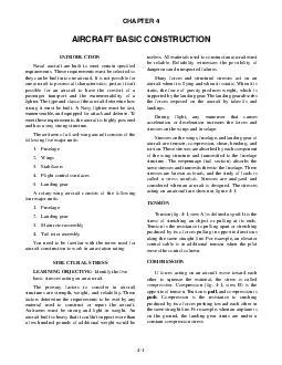
These requirements must be selected so they can be built into one aircraft It is not possible for one aircraft to possess all characteristics just as it isnt possible for an aircraft to have the comfort of a passenger transport and the maneuverabili ID: 2008

These requirements must

Share:

Link:

Embed:

Download Presentation from below link

Download Pdf The PPT/PDF document "CHAPTER AIRCRAFT BASIC CONSTRUCTION INT..." is the property of its rightful owner. Permission is granted to download and print the materials on this web site for personal, non-commercial use only, and to display it on your personal computer provided you do not modify the materials and that you retain all copyright notices contained in the materials. By downloading content from our website, you accept the terms of this agreement.


Presentation Transcript

AIRCRAFT BASIC CONSTRUCTIONINTRODUCTIONNavalaircraftarebuilttomeetcertainspecifiedrequirements.Theserequirementsmustbeselectedsotheycanbebuiltintooneaircraft.Itisnotpossibleforoneaircrafttopossessallcharacteristics;justasitisn'tpossibleforanaircrafttohavethecomfortofa Cuttingapieceofpaperwithscissorsisanexampleofashearingaction.Inanaircraftstructure,shear(fig.4-1,viewD)isastressexertedwhentwopiecesoffastenedmaterialtendtoseparate.Shearstressistheoutcomeofslidingonepartovertheotherinoppositedirections.TherivetsandboltsofanaircraftexperienceBending(fig.4-1,viewE)isacombinationoftensionandcompression.Forexample,whenbendingapieceoftubing,theupperportionstretches(tension)andthelowerportioncrushestogether(compression).ThewingsparsofanaircraftinflightaresubjecttoTORSIONTorsional(fig.4-1,viewC)stressesresultfromatwistingforce.Whenyouwringoutachamoisskin,youareputtingitundertorsion.Torsionisproducedinanenginecrankshaftwhiletheengineisrunning.ForcesVARYING STRESSAllstructuralmembersofanaircraftaresubjecttooneormorestresses.Sometimesastructuralmemberhasalternatestresses;forexample,itisundercompressiononeinstantandundertensionthenext.Thestrengthofaircraftmaterialsmustbegreatenoughto withstand maximum force of varying stresses.SPECIFIC ACTION OF STRESSESYouneedtounderstandthestressesencounteredonthemainpartsofanaircraft.Aknowledgeofthebasicstressesonaircraftstructureswillhelpyouunderstandwhyaircraftarebuiltthewaytheyare.Thefuselageofanaircraftissubjectthefivestypesofstress—torsion,bending, tension, shear, and compression.Torsionalstressinafuselageiscreatedinseveralways.Forexample,torsionalstressisencounteredinenginetorqueonturbopropaircraft.Enginetorquetendstorotatetheaircraftinthedirectionoppositetothedirectionthepropelleristurning.Thisforcecreatesatorsionalstressinthefuselage.Figure4-2showstheeffectoftherotatingpropellers.Also,torsionalstressonthefuselageiscreatedbytheactionoftheaileronswhen the aircraft is maneuvered.Whenanaircraftisontheground,thereisabendingforceonthefuselage.Thisforceoccursbecauseoftheweightoftheaircraft.Bendingincreaseswhentheaircraftmakesacarrierlanding.Thisbendingactioncreatesatensionstressonthelowerskinofthefuselageandacompressionstressonthetopskin.Bendingactionisshowninfigure4-3.Thesestressesaretransmittedtothefuselagewhentheaircraftisinflight.Bendingoccursbecauseofthereactionoftheairflowagainstthewingsandempennage.WhentheFigure 4-1.—Five stresses acting on an aircraft. aircraftisinflight,liftforcesactupwardagainstthewings,tendingtobendthemupward.Thewingsarepreventedfromfoldingoverthefuselagebytheresistingstrengthofthewingstructure.Thebendingactioncreatesatensionstressonthebottomofthewingsandacompressionstressonthetopofthewings.Q4-1.Theresistancetopullingapartorstretchingproducedbytwoforcespullinginoppositedirectionsalongthesamestraightlinesisdefined by what term?Q4-2.Theresistancetocrushingproducedbytwoforcespushingtowardeachotherinthesamestraight line is defined by what term?Q4-3.Definethetermshearasitrelatestoanaircraft structure.Q4-4.Define the term bending.Q4-5.Define the term torsion.CONSTRUCTION MATERIALSLEARNINGOBJECTIVE:IdentifythevarioustypesofmetallicandnonmetallicAnaircraftmustbeconstructedofmaterialsthatarebothlightandstrong.Earlyaircraftweremadeofwood.Lightweightmetalalloyswithastrengthgreaterthanwoodweredevelopedandusedonlateraircraft.MaterialscurrentlyusedinaircraftconstructionareclassifiedaseithermetallicmaterialsornonmetallicTORSIONALROTATIONFigure 4-2.—Engine torque creates torsion stress in aircraft fuselages.Figure 4-3.—Bending action occurring during carrier landing. METALLIC MATERIALSThemostcommonmetalsusedinaircraftconstructionarealuminum,magnesium,titanium,steel, and their alloys.Analloyiscomposedoftwoormoremetals.Themetalpresentinthealloyinthelargestamountiscalledbasemetal.Allothermetalsaddedtothebasemetalarecalledalloyingelements.Addingthealloyingelementsmayresultinachangeinthepropertiesofthebasemetal.Forexample,purealuminumisrelativelysoftandweak.However,addingsmallamountsorcopper,manganese,andmagnesiumwillincreasealuminum'sstrengthmanytimes.Heattreatmentcanincreaseordecreaseanalloy'sstrengthandhardness.Alloysareimportanttotheaircraftindustry.TheyprovidematerialswithpropertiesthatpuremetalsdoAluminumalloysarewidelyusedinmodernaircraftconstruction.Aluminumalloysarevaluablebecausetheyhaveahighstrength-to-weightratio.Aluminumalloysarecorrosionresistantandcomparativelyeasytofabricate.TheoutstandingMagnesiumistheworld'slighteststructuralmetal.Itisasilvery-whitematerialthatweighstwo-thirdsasmuchasaluminum.Magnesiumisusedtomakehelicopters.Magnesium'slowresistancetocorrosionhas limited its use in conventional aircraft.TitaniumTitaniumisalightweight,strong,corrosion-resistantmetal.Recentdevelopmentsmaketitaniumidealforapplicationswherealuminumalloysaretooweakandstainlesssteelistooheavy.Additionally,titaniumisunaffectedbylongexposuretoseawaterandAlloysteelsusedinaircraftconstructionhavegreatstrength,moresothanotherfieldsofengineeringwouldrequire.Thesematerialsmustwithstandtheforcesthatoccurontoday'smodernaircraft.Thesesteelscontainsmallpercentagesofcarbon,nickel,chromium,vanadium,andmolybdenum.High-tensilesteelswillstandstressof50to150tonspersquareinchwithoutfailing.Suchsteelsaremadeintotubes,rods,Anothertypeofsteelusedextensivelyisstainlesssteel.Stainlesssteelresistscorrosionandisparticularlyvaluable for use in or near water.NONMETALLIC MATERIALSInadditiontometals,varioustypesofplasticmaterialsarefoundinaircraftconstruction.Someoftheseplasticsincludetransparentplastic,reinforcedplastic, composite, and carbon-fiber materials.Transparent PlasticTransparentplasticisusedincanopies,windshields,andothertransparentenclosures.Youneedtohandletransparentplasticsurfacescarefullybecausetheyarerelativelysoftandscratcheasily.Atapproximately225°F,transparentplasticbecomessoftReinforced PlasticReinforcedplasticisusedintheconstructionofradomes,wingtips,stabilizertips,antennacovers,andflightcontrols.Reinforcedplastichasahighstrength-to-weightratioandisresistanttomildewandrot.Becauseitiseasytofabricate,itisequallysuitableReinforcedplasticisasandwich-typematerial(fig.4-4).Itismadeupoftwoouterfacingsandacenterlayer.Thefacingsaremadeupofseverallayersofglasscloth,bondedtogetherwithaliquidresin.Thecorematerial(centerlayer)consistsofahoneycombFACINGS(MULTIPLELAYERSOFGLASSCLOTH)Figure 4-4.—Reinforced plastic. structuremadeofglasscloth.Reinforcedplasticisfabricated into a variety of cell sizes.High-performanceaircraftrequireanextrahighstrength-to-weightratiomaterial.Fabricationofcompositematerialssatisfiesthisspecialrequirement.Compositematerialsareconstructedbyusingseverallayersofbondingmaterials(graphiteepoxyorboronepoxy).Thesematerialsaremechanicallyfastenedtoconventionalsubstructures.Anothertypeofcompositeconstructionconsistsofthingraphiteepoxyskinsbondedtoanaluminumhoneycombcore.Carbonfiberisextremelystrong,thinfibermadebyheatingsyntheticfibers,suchasrayon,untilcharred,andthenQ4-6.Materialscurrentlyusedinaircraftconstruc-tion are classified as what type of materials?Q4-7.Whatarethemostcommonmetallicmaterialsused in aircraft construction?Q4-8.Whatarethenonmetallicmaterialsusedinaircraft construction?LEARNINGOBJECTIVE:Identifytheconstructionfeaturesofthefixed-wingaircraftandidentifytheprimary,secondary,andauxiliary flight control surfaces.Theprincipalstructuralunitsofafixed-wingaircraftarethefuselage,wings,stabilizers,flightcontrolsurfaces,andlandinggear.Figure4-5showsthese units of a naval aircraft.NOTE:ThetermsusedinrelationtoanyofthestructuralunitsrefertotherightorlefthandFUSELAGEThefuselageisthemainstructure,orbody,oftheaircraft.Itprovidesspaceforpersonnel,cargo,controls,andmostoftheaccessories.Thepowerplant,HORIZONTALSTABILIZEROFWINGVERTICALSTABILIZERAIRINLETFAIRINGELEVATORFigure 4-5.—Principal structural units on an F-14 aircraft. Therearetwogeneraltypesoffuselageconstruction—weldedsteeltrussandmonocoquedesigns.TheweldedsteeltrusswasusedinsmallerNavyaircraft,anditisstillbeingusedinsomeThemonocoquedesignrelieslargelyonthestrengthoftheskin,orcovering,tocarryvariousloads.Themonocoquedesignmaybedividedintothreeclasses—monocoque,semimonocoque,andreinforcedThetruemonocoqueconstructionusesformers,frameassemblies,andbulkheadstogiveshapetothefuselage.However,theskincarriestheprimarystresses.Sincenobracingmembersarepresent,theskinmustbestrongenoughtokeepthefuselagerigid.ThebiggestprobleminmonocoqueconstructionismaintainingenoughstrengthwhilekeepingtheSemimonocoquedesignovercomesthestrength-to-weightproblemofmonocoqueconstruction.Seefigure4-6.Inadditiontohavingformers,frameassemblies,andbulkheads,thesemimonocoqueconstructionhastheskinreinforcedbylongitudinalThereinforcedshellhastheskinreinforcedbyacompleteframeworkofstructuralmembers.Differentportionsofthesamefuselagemaybelongtoanyoneofthethreeclasses.Mostareconsideredtobeofsemimonocoque-typeThesemimonocoquefuselageisconstructedprimarilyofaluminumalloy,althoughsteelandtitaniumarefoundinhigh-temperatureareas.Primarybendingloadsaretakenbythelongerons,whichusuallyextendacrossseveralpointsofsupport.Thelongeronsaresupplementedbyotherlongitudinalmembersknownasstringers.StringersaremoreTheverticalstructuralmembersarereferredtoasbulkheadsframes,andformers.Theheavierverticalmembersarelocatedatintervalstoallowforconcentratedloads.Thesemembersarealsofoundatpointswherefittingsareusedtoattachotherunits,suchThestringersaresmallerandlighterthanlongeronsandserveasfill-ins.Theyhavesomerigiditybutarechieflyusedforgivingshapeandforattachmentofskin.Thestrong,heavylongeronsholdthebulkheadsandformers.Thebulkheadsandformersholdthestringers.Allofthesejointogethertoformarigidfuselageframework.StringersandlongeronspreventtensionandcompressionstressesfrombendingtheTheskinisattachedtothelongerons,bulkheads,andotherstructuralmembersandcarriespartoftheload.Thefuselageskinthicknessvarieswiththeloadcarriedandthestressessustainedatparticularloca-Figure 4-6.—Semimonocoque fuselage construction. ThereareanumberofadvantagesinusingtheThebulkhead,frames,stringers,andlongeronsaidinthedesignandconstructionofastreamlinedfuselage.TheyaddtothestrengthThemainadvantageofthesemimonocoqueconstructionisthatitdependsonmanystructuralmembersforstrengthandrigidity.Becauseofitsstressedskinconstruction,asemimonocoquefuselagecanwithstanddamageandstillbestrongenoughtoholdtogether.Pointsonthefuselagearelocatedbystationnumbers.Station0isusuallylocatedatornearthenoseoftheaircraft.Theotherstationsarelocatedatmeasureddistances(ininches)aftofstation0.Atypicalstationdiagramisshowninfigure4-7.Onthisparticularaircraft,fuselagestation(FS)0islocated93.0 inches forward of the nose.050100150200250300350400450500550600650700750800850ARRESTINGHOOKFULLYEXTENDEDSTATICFS-FUSELAGESTATIONWS-WINGSTATIONAIRCRAFTSTATIONS20WING75WINGFigure 4-7.—Fuselage station diagram of an F-14 aircraft. Wingsdevelopthemajorportionoftheliftofaheavier-than-airaircraft.Wingstructurescarrysomeoftheheavierloadsfoundintheaircraftstructure.Theparticulardesignofawingdependsonmanyfactors,suchasthesize,weight,speed,rateofclimb,anduseoftheaircraft.Thewingmustbeconstructedsothatitholdsitsaerodynamicsshapeundertheextremestresses of combat maneuvers or wing loading.Wingconstructionissimilarinmostmodernaircraft.Initssimplestform,thewingisaframeworkmadeupofsparsandribsandcoveredwithmetal.Theconstructionofanaircraftwingisshowninfigure4-8.Sparsarethemainstructuralmembersofthewing.Theyextendfromthefuselagetothetipofthewing.Alltheloadcarriedbythewingistakenupbythespars.Thesparsaredesignedtohavegreatbendingstrength.Ribsgivethewingsectionitsshape,andtheytransmittheairloadfromthewingcoveringtothespars.RibsextendfromtheleadingedgetothetrailingedgeoftheInadditiontothemainspars,somewingshaveafalsespartosupporttheaileronsandflaps.Mostaircraftwingshavearemovabletip,whichstreamlinesMostNavyaircraftaredesignedwithawingreferredtoasawetwing.Thistermdescribesthewingthatisconstructedsoitcanbeusedasafuelcell.Thewetwingissealedwithafuel-resistantcompoundasitisbuilt.ThewingholdsfuelwithouttheusualrubberThewingsofmostnavalaircraftareofallmetal,fullcantileverconstruction.Often,theymaybefoldedforcarrieruse.Afullcantileverwingstructureisverystrong.Thewingcanbefastenedtothefuselagewithouttheuseofexternalbracing,suchaswiresorAcompletewingassemblyconsistsofthesurfaceprovidingliftforthesupportoftheaircraft.Italsoprovides the necessary flight control surfaces.NOTE:Theflightcontrolsurfacesonasimplewingmayincludeonlyaileronsandtrailingedgeflaps.Themorecomplexaircraftmayhaveavarietyofdevices,suchasleadingedgeflaps,slats,spoilers,andspeed brakes.Variouspointsonthewingarelocatedbywingstationnumbers(fig.4-7).Wingstation(WS)0islocatedatthecenterlineofthefuselage,andallwingstationsaremeasured(rightorleft)fromthispoint(inSTABILIZERSThestabilizingsurfacesofanaircraftconsistofverticalandhorizontalairfoils.TheyarecalledtheTRAILINGEDGESPARSLEADINGEDGEFigure 4-8.—Two-spar wing construction. verticalstabilizerfin)andhorizontalstabilizerThesetwoairfoils,alongwiththerudderandelevators,formthetailsection.Forinspectionandmaintenancepurposes,theentiretailsectionisconsideredasingleempennageThemainpurposeofstabilizersistokeeptheaircraftinstraight-and-levelflight.Theverticalstabilizermaintainsthestabilityofheaircraftaboutitsverticalaxis(fig.4-9).Thisisknownasdirectional.Theverticalstabilizerusuallyservesasthebasetowhichtherudderisattached.Thehorizontalstabilizerprovidesstabilityoftheaircraftaboutitslateralaxis.Thisisknownaslongitudinalstability.Thehorizontalstabilizerusuallyservesasthebasetowhichtheelevatorsareattached.Onmanynewer,high-performanceaircraft,theentireverticaland/orhorizontalstabilizerisamovableairfoil.Withoutthemovableairfoil,theflightcontrolsurfaceswouldlosetheir effectiveness at extremely high altitudes.Stabilizerconstructionissimilartowingconstruction.Forgreaterstrength,especiallyinthethinnerairfoilsectionstypicaloftrailingedges,ahoneycomb-typeconstructionisused.Somelargercarrier-typeaircrafthaveverticalstabilizersthatarefoldedhydraulicallytoaidaircraftmovementaboardFLIGHT CONTROL SURFACESFlightcontrolsurfacesarehinged(movable)airfoilsdesignedtochangetheattitudeoftheaircraftduringflight.Thesesurfacesaredividedintothreegroups—primary, secondary, and auxiliary.Primary GroupTheprimarygroupofflightcontrolsurfacesincludesailerons,elevators,andrudders.Theaileronsattachtothetrailingedgeofthewings.Theycontroltherolling(orbanking)motionoftheaircraft.Thisactionis known aslongitudinal controlTheelevatorsareattachedtothehorizontalstabilizerandcontroltheclimbordescent(pitchingmotion)oftheaircraft.ThisactionisknownaslateralcontrolTherudderisattachedtotheverticalstabilizer.Itdeterminesthehorizontalflight(turningoryawingmotion)oftheaircraft.Thisactionisknownasdirectional controlTheaileronsandelevatorsareoperatedfromthecockpitbyacontrolstickonsingle-engineaircraft.Ayokeandwheelassemblyoperatestheaileronsandelevatorsonmultiengineaircraft,suchastransportandYAWVERTICALAXISLATERALAXISLONGITUDINALAXISFigure 4-9.—Axes and fundamental movements of the aircraft. patrolaircraft.TherudderisoperatedbyfootpedalsonSecondary GroupThesecondarygroupincludesthetrimtabsandspringtabs.Trimtabsaresmallairfoilsrecessedintothetrailingedgesoftheprimarycontrolsurface.Eachtrimtabhingestoitsparentprimarycontrolsurface,butoperatesbyanindependentcontrol.TrimtabsletthepilottrimoutanunbalancedconditionwithoutexertingSpringtabsaresimilarinappearancetotrimtabsbutserveanentirelydifferentpurpose.Springtabsareusedforthesamepurposeashydraulicactuators.Theyaidthepilotinmovingalargercontrolsurface,suchasthe ailerons and elevators.Auxiliary GroupTheauxiliarygroupincludesthewingflaps,spoilers, speed brakes, and slats.WINGFLAPS.—Wingflapsgivetheaircraftextralift.Theirpurposeistoreducethelandingspeed.Reducingthelandingspeedshortensthelengthofthelandingrollout.Flapshelpthepilotlandinsmallorobstructedareasbyincreasingtheglideanglewithoutgreatlyincreasingtheapproachspeed.TheuseofflapsduringtakeoffservestoreducethelengthofthetakeoffSomeflapshingetothelowertrailingedgesofthewingsinboardoftheailerons.LeadingedgeflapsareusedontheF-14TomcatandF/A-18.Fourtypesofflapsareshowninfigure4-10.Theplainflapformsthetrailingedgeoftheairfoilwhentheflapisintheupposition.Inthesplitflap,thetrailingedgeoftheairfoilissplit,andthelowerhalfishingedandlowerstoformtheflap.Thefowlerflapoperatesonrollersandtracks,causingthelowersurfaceofthewingtorolloutandthenextenddownward.Theleadingedgeflapoperatesliketheplainflap.Itishingedonthebottomside.Whenactuated,theleadingedgeofthewingactuallyextendsinadownwarddirectiontoincreasethecamberofthewing.LandingflapsareusedinSpoilersareusedtodecreasewinglift.Thespecificdesign,function,andusevarywithdifferentaircraft.Onsomeaircraft,thespoilersarelongnarrowsurfaces,hingedattheirleadingedgetotheuppersurfacesofthewings.Intheretractedposition,theyareflushwiththewingskin.Intheraisedposition,theygreatlyreducewingliftbydestroyingthesmoothflow of air over the wing surface.SPEEDBRAKES.—Speedbrakesaremovablecontrolsurfacesusedforreducingthespeedoftheaircraft.Somemanufacturersrefertothemasbrakes;othersrefertothemasdiveflaps.Onsomeaircraft,they'rehingedtothesidesorbottomofthefuselage.Regardlessoftheirlocation,speedbrakesservethesamepurpose—tokeeptheairspeedfrombuildingtoohighwhentheaircraftdives.Speedbrakesslow the aircraft's speed before it lands.SLATS.—Slatsaremovablecontrolsurfacesthatattachtotheleadingedgeofthewing.Whentheslatisretracted,itformstheleadingedgeofthewing.Whentheslatisopen(extendedforward),aslotiscreatedbetweentheslatandthewingleadingedge.High-energyairisintroducedintotheboundarylayeroverthetopofthewing.Atlowairspeeds,thisactionimprovesthelateralcontrolhandlingcharacteristics.Thisallowstheaircrafttobecontrolledatairspeedsbelownormallandingspeed.Thehigh-energyairthatflowsoverthetopofthewingisknownaslayercontrolair.Boundarylayercontrolisintendedprimarilyforuseduringoperationsfromcarriers.Boundarylayercontrolairaidsincatapulttakeoffsandarrestedlandings.Boundarycontrolaircanalsobeaccomplishedbydirectinghigh-pressureenginebleedair across the top of the wing or flap surface.SPLITFLAPLEADINGEDGEFLAPPLAINFLAPFOWLERFLAPFigure 4-10.—Types of flaps. FLIGHT CONTROL MECHANISMSThetermflightcontrolreferstothelinkagethatconnectsthecontrol(s)inthecockpitwiththeflightcontrolsurfaces.Thereareseveraltypesofflightcontrolsinnavalaircraft;somearemanuallyoperatedwhile others are power operated.Manuallyoperatedflightcontrolmechanismsarefurtherdividedintothreegroups—cableoperated,push-pulltubeoperated,andtorquetubeoperated.Somesystemsmaycombinetwoormoreofthesetypes.Inthemanuallyoperatedcablesystem,cablesareconnectedfromthecontrolinthecockpittoabellcrankorsector.Thebellcrankisconnectedtothecontrolsurface.Movementofthecockpitcontrolstransfersforcethroughthecabletothebellcrank,whichmovesthe control surface.Inapush-pulltubesystem,metalpush-pulltubes(orrods)areusedasasubstituteforthecables(fig.4-11).Push-pulltubesgettheirnamefromthewaytheyInthetorquetubesystem,metaltubes(rods)withgearsattheendsofthetubesareused.MotionisOnallhigh-performanceaircraft,thecontrolsurfaceshavegreatpressureexertedonthem.Athighairspeed,itisphysicallyimpossibleforthepilottomovethecontrolsmanually.Asaresult,power-operatedcontrolmechanismsareused.Inapower-operatedsystem,ahydraulicactuator(cylinder)islocatedwithinthelinkagetoassistthepilotinmoving the control surface.Atypicalflightcontrolmechanismisshowninfigure4-12.Thisistheelevatorcontrolofalightweighttrainer-typeaircraft.ItconsistsofacombinationofThecontrolsticksinthesystemshowninfigure4-12areconnectedtotheforwardsectorbypush-pulltubes.Theforwardsectorisconnectedtotheaft(rear)sectorbymeansofcableassemblies.Theaftsectorisconnectedtotheflightcontrolbyanotherpush-pulltube assembly.BeforeWorldWarII,aircraftweremadewiththeirmainlandinggearlocatedbehindthecenterofgravity.Anauxiliarygearunderthefuselagenosewasadded.Thisarrangementbecameknownasthetricycletypeoflandinggear.Nearlyallpresent-dayNavyaircraftareequippedwithtricyclelandinggear.Thetricyclegearhas the following advantages over older landing gear:Maintains the fuselage in a level positionMakeslandingeasier,especiallyincrosswindsANf0411Figure 4-11.—Push-pull tube assembly.Figure 4-12.—Typical flight control mechanism. Thelandinggearsystem(fig.4-13)consistsofthreeretractablelandinggearassemblies.Eachmainlandinggearhasaconventionalair-oilshockstrut,awheelbrakeassembly,andawheelandtireassembly.Thenoselandinggearhasaconventionalair-oilshockstrut,ashimmydamper,andawheelandtireassembly.Theshockstrutisdesignedtoabsorbtheshockthatwouldotherwisebetransmittedtotheairframeduringlanding,taxiing,andtakeoff.Theair-oilstrutisusedonallnavalaircraft.Thistypeofstruthastwotelescopingcylindersfilledwithhydraulicfluidandcompressedairornitrogen.Figure4-14showstheinternalconstructionof one type of air-oil shock strut.ThemainlandinggearisequippedwithbrakesforstoppingtheaircraftandassistingthepilotinsteeringThenosegearofmostaircraftcanbesteeredfromthecockpit.ThisprovidesgreatereaseandsafetyontherunwaywhenlandingandtakingoffandonthetaxiwayAcarrier-typeaircraftisequippedwithanarrestinghookforstoppingtheaircraftwhenitlandsonthecarrier.Thearrestinggearhasanextendiblehookandthemechanical,hydraulic,andpneumaticequipmentnecessaryforhookoperation.Seefigure4-15.Thearrestinghookonmostaircraftreleasesmechanically,lowers pneumatically, and raises hydraulically.Thehookhingesfromthestructureundertherearoftheaircraft.Asnubbermetershydraulicfluidandworksinconjunctionwithnitrogenpressure.TheACTUATINGSELECTORVALVEDOORANDDOORLATCHMAINGEARTOLEFTMAINGEARNOSEGEARTIMERVALVESAREUSEDINMAINGEARSYSTEMTOCONTROLPROPERSEQUENCE.Anf0413Figure 4-13.—Typical landing gear system.TOWINGEYETORQUEMETERINGPIN(PISTON)AIRVALVEWHEELAXLEORIFICEPLATEFigure 4-14.—Internal construction of a shock strut. snubberholdsthehookdownandpreventsitfrombouncing when it strikes the carrier deck.CATAPULT EQUIPMENTCarrieraircrafthavebuilt-inequipmentforcatapultingofftheaircraftcarrier.Olderaircrafthadhooksontheairframethatattachedtothecablebridle.Thebridlehookstheaircrafttotheship'scatapult.Neweraircrafthavealaunchbarbuiltintothenoselandinggearassembly.Seefigure4-16.Theholdbackassemblyallowstheaircrafttobesecuredtothecarrierdeckforfull-powerturnupoftheenginepriortotakeoff.Fornosegearequipment,atrackattachestothedecktoguidethenosewheelintoposition.ThetrackhasprovisionsforattachingthenosegeartothecatapultNOTE:Theholdbacktensionbarseparateswhenthecatapultisfired,allowingtheaircrafttobelaunchedwith the engine at full power.Q4-9.Infuselageconstruction,whatarethethreeQ4-10.PointsonthefuselagearelocatedbywhatQ4-11.Inanaircraft,whatarethemainstructuralmembers of the wing?Q4-12.What does the term “wet wing” mean?Q4-13.ThestabilizingsurfacesofanaircraftconsistQ4-14.WhatarethethreegroupsofflightcontrolQ4-15.Whatisthepurposeofspeedbrakesonanaircraft?Q4-16.Mostpresent-dayNavyaircraftareequippedwith what type of landing gear?ROTARY-WING AIRCRAFTLEARNINGOBJECTIVE:Identifytheconstructionfeaturesoftherotary-wingaircraftandrecognizethefundamentaldifferencesbetweenrotary-wingandfixed-wing aircraft.Withinthepast20years,helicoptershavebecomeareality,andarefoundthroughouttheworld.TheyperformcountlesstaskssuitedtotheiruniqueAhelicopterhasoneormorepower-drivenhorizontalairscrews(rotors)todevelopliftandpropulsion.Ifasinglemainrotorisused,itisnecessarytoemployameanstocounteracttorque.Ifmorethanonemainrotor(ortandem)isused,torqueiseliminatedThefundamentaladvantagethehelicopterhasoverfixed-wingaircraftisthatliftandcontrolareindependentofforwardspeed.Ahelicoptercanflyforward,backward,orsideways,oritcanremaininstationaryflight(hover)abovetheground.Norunwayisrequiredforahelicoptertotakeofforland.Forexample,theroofofanofficebuildingisanadequatelandingarea.Thehelicopterisconsideredasafeaircraftbecausethetakeoffandlandingspeediszero,andithasautorotationalcapabilities.ThisallowsacontrolleddescentwithrotorsturningincaseofenginefailureinFUSELAGELikethefuselageofafixed-wingaircraft,thehelicopterfuselagemaybeweldedtrussorsomeformofmonocoqueconstruction.ManyNavyhelicoptersareFigure 4-15.—Arresting gear installation. CATAPULTCATAPULTAIRCRAFTCATAPULTBRIDLEHOOKSBRIDLEARRESTERLANYARDSLIDELANYARDCATAPULTCATAPULTCATAPULTLANYARDCATAPULTCATAPULTLANYARDCLEATDECKCLEATCATAPULTHOLDBACKAIRCRAFTCATAPULTHOLDBACKFITTINGFigure 4-16.—Aircraft catapult equipment. AtypicalNavyhelicopter,theH-60,isshowninfigure4-17.Someofitsfeaturesincludeasinglemainrotor,twinengine,tractor-typecantedtailrotor,controllablestabilizer,fixedlandinggear,rescuehoist,externalcargohook,andweaponspylons.Thefuselageconsistsoftheentireairframe,sometimesknownasthebody groupThebodygroupisanall-metalsemimonocoqueconstruction.Itconsistsofanaluminumandtitaniumskin over a reinforced aluminum frame.LANDING GEAR GROUPThelandinggeargroupincludesalltheequipmentnecessarytosupportthehelicopterwhenitisnotinflight.Thereareseveraltypesoflandinggearonhelicopters—conventionalfixed(skidtype),TheH-60'snonretractingmainlandinggearconsistsoftwosingleaxle,air/oiltypeofshock-strutassembliesthatmounttothefuselage.Eachisequippedwithtubelesstires,hydraulicdiscbrakes,tie-downrings,dragbraces,andsafetyswitches.Theyarepartofthe lower end of the shock strut piston.Tail Landing GearTheH-60'staillandinggearisanonretracting,dualwheel,360-degreeswivelingtype.Itisequippedwithtubelesstires,tie-downring,shimmydamper,tail-wheellock,andanair/oilshock-strut,whichservesasanafttouchdownpointforthepilotstocushiontheMAIN ROTOR ASSEMBLYThemainrotor(rotorwing)androtorhead(hubassembly)areidenticalintheoryofflightbutdifferinengineeringordesign.Theyarecoveredherebecausetheirfunctionsarecloselyrelated.Thepowerplant,transmission,drive-train,hydraulicflightcontrol,androtorsystemsallworktogether.Neitherhasafunctionwithout the other.Rotary WingThemainrotorontheH-60(fig.4-17)hasfouridenticalwingblades.OthertypesofhelicoptersmayAnf0417Figure 4-17.—H-60 helicopter. havetwo,four,five,six,orsevenblades.Figure4-18shows some typical rotor blades.Rotary-wingbladesaremadeoftitanium,aluminumalloys,fiberglass,graphite,honeycombcore,nickel,andsteel.Eachhasanitrogen-filled,pressurized,hollowinternalspar,whichrunsthelengthoftheblade.Thecuffprovidestheattachmentofthebladetotherotorhub.Atitaniumabrasionstripcoverstheentireleadingedgeofthesparfromthecuffendtotheremovablebladetipfaring.ThisextendsthelifeofTheexamplesshowninfigure4-18showotherfeatures—trimtabs,deicingprotection,balanceTherotorheadisfullyarticulatingandisrotatedbytorquefromtheenginesthroughthedrivetrainandmaingearboxortransmission.Theflightcontrolsandhydraulicservostransmitmovementstotherotorblades.Theprincipalcomponentsoftherotorheadarethehubandswashplateassemblies(fig.4-19).Theisonepiece,madeoftitaniumandsitsontopoftherotormast.Attachingcomponentsarethesleeveandspindles,bladefoldcomponents,vibrationabsorber,bearings,bladedampers,pitchchangehorns,adjustablepitchcontrolrods,bladefoldhinges,balanceweights, antiflapping and droop stops, and faring.consistsofarotatingdisc(upper),stationary(lower)portionwithascissorsandsleeveassemblyseparatedbyabearing.Theswashplateispermittedtoslideonthemainrotorverticaldriveshaftandmountsontopthemaintransmission.TheentireassemblycantiltinanydirectionfollowingthemotionThehydraulicservocylinders,swashplate,andadjustablepitchcontrolrodspermitmovementoftheABRASIONSTRIPBALANCESTRIPTRIMTABSTIPCAPBLADECUFFBLADEINSPECTIONINDICATORROOTPOCKETICEGUARDSPARSPARABRASIONTIPCAPPOCKETIDENTIFICATIONFigure 4-18.—Types of main rotor blades. flightcontrolstobetransmittedtotherotary-wingblades.Thesleeveandspindleandbladedampersallowlimitedmovementofthebladesinrelationtothehub.These movements are known aslagLeadoccursduringslowingofthedrivemechanismwhenthebladeshaveatendencytoLagistheoppositeofleadandoccursduringaccelerationwhenthebladehasbeenatrestFlapisthetendencyofthebladetorisewithhigh-liftdemandsasittriestoscrewitselfupward into the air.Antiflappingstopsanddroopstopsrestrictflappingandconningmotionoftherotary-wingheadandbladesat low rotor rpm when slowing or stopping.TAIL ROTOR GROUPThedirectionalcontrolandantitorqueactionofthehelicopterisprovidedbythetailrotorgroup.SeeBLADEFOLDACTUATORFAIRINGPITCHLOCKACTUATORROTORHUBASSEMBLYROTATINGSCISSORSLOWERPRESSUREPLATESWASHPLATEPITCHCONTROLPITCHCHANGEANf0119ROTORHEADFigure 4-19.—Main rotor head/hub assembly. figure4-20.Thesecomponentsaresimilarinfunctionto the main rotor.Thepylon,showninfigure4-20,attachesontheaircrafttothemainfuselagebyhingefittings.Thesehingefittingsserveasthepivotpointforthepylontofoldalongthefuselage.Foldingthepylonreducestheoveralllengthofthehelicopter,whichhelpsforconfined shipboard handling.Thepylonhousestheintermediateandtailrotorgearboxes,tailrotordriveshaft,cover,tailbumper,position/anticollisionlights,hydraulicservos,flightcontrolpush-pulltubes/cables/bellcranks,stabilizer/elevatorflightcontrolsurface,someantennas,androtary rudder assembly.Therudderheadcanbelocatedoneithersideofthepylon,dependingonthetypeofaircraft,andincludessuchitemsasthehub,spindle,pitchcontrolbeam,pitchChangeinbladepitchisaccomplishedthroughthepitchchangeshaftthatmovesthroughthehorizontalshaftofthetailgearbox,whichdrivestherotaryrudderassembly.Astheshaftmovesinwardtowardthetailgearbox,pitchofthebladeisdecreased.Astheshaftmovesoutwardfromthetailgearbox,pitchofthebladeisincreased.Thepitchcontrolbeamisconnectedbylinks to the forked brackets on the blade sleeves.Likethebladesonamainrotorhead,thebladesfoundonarotaryrudderheadmaydiffer,dependingonthetypeofaircraft.Tailrotorbladesmayconsistofthefollowing components:Aluminumalloy,graphitecomposite,orAluminumpocketandskinwithhoneycombcore or cross-ply fiber glass exteriorPITCHCHANGELINKROTARYRUDDERBLADEROTARYRUDDERHUBPITCHCONTROLBEAMTAILROTORGEARBOXFigure 4-20.—Tail rotor group. AluminumorpolyurethaneandnickelabrasionAdditionally,rotaryrudderbladesmayhavedeicingprovisions,suchaselectrothermalblanketsthatarebondedintotheblade'sleadingedge.oraneopreneanti-icingguardembeddedwithelectricalheatingQ4-17.Whatisthemainadvantageofrotary-wingaircraft over fixed-wing aircraft?Q4-18.Whatarethethreetypesoflandinggearusedon helicopters?Q4-19.Thedirectionalcontrolandantitorqueactionof the helicopter is provided by what group?AIRCRAFT HYDRAULIC SYSTEMSLEARNINGOBJECTIVE:IdentifythecomponentsofaircrafthydraulicsystemsandTheaircrafthydraulicsystemsfoundonmostnavalaircraftperformmanyfunctions.Somesystemsoperatedbyhydraulicsareflightcontrols,landinggear,speedbrakes,fixed-wingandrotary-wingfoldingmechanisms, auxiliary systems, and wheel brakes.HydraulicshasmanyadvantagesasapowersourceHydraulicscombinetheadvantagesoflightweight,easeofinstallation,simplificationofinspection,andminimummaintenanceHydraulicsoperationisalmost100-percentefficient,withonlyanegligiblelossduetoHowever,therearesomedisadvantagestousinghydraulics.Thepossibilityofleakage,bothinternalandexternal,maycausethecompletesystemtobecome inoperative.Contaminationbyforeignmatterinthesystemcancausemalfunctionofanyunit.Cleanlinessin hydraulics cannot be overemphasized.COMPONENTS OF A BASIC HYDRAULICBasically,anyhydraulicsystemcontainsthefollowing units:reservoirtoholdasupplyofhydraulicfluidto provide a flow of fluidTubingselector valveto direct the flow of fluidactuatingunittoconvertthefluidpressureinto useful workAsimplesystemusingtheseessentialunitsisshown in figure 4-21.Youcantracetheflowoffluidfromthereservoirthroughthepumptotheselectorvalve.Infigure4-21,theflowoffluidcreatedbythepumpflowsthroughthevalvetotherightendoftheactuatingcylinder.Fluidpressureforcesthepistontotheleft.Atthesametime,thefluidthatisontheleftofthepistonisforcedout.Itgoesupthroughtheselectorvalveandbacktothereservoir through the return line.Whentheselectorvalveismovedtothepositionindicatedbythedottedlines,thefluidfromthepumpflowstotheleftsideoftheactuatingcylinder.Movementofthepistoncanbestoppedatanytimesimplybymovingtheselectorvalvetoneutral.Whentheselectorvalveisinthisposition,allfourportsareclosed, and pressure is trapped in both working lines.ANF0421PRESSURELINESELECTORVALVEIN"DOWN"SELECTORVALVEIN"UP"ACTUATINGRESERVOIRFigure 4-21.—Basic hydraulic system, hand pump operated. Figure4-22showsabasicsystemwiththeadditionofapower-drivenpumpandotheressentialcomponents.Thesecomponentsarethefilter,pressureregulator,accumulator,pressuregauge,reliefvalve,andtwocheckvalves.Thefunctionofthesecomponents is described below.filter(fig.4-22)removesforeignparticlesfromthefluid,preventingmoisture,dust,grit,andotherpressureregulator(fig.4-22)unloadsorrelievesthepower-drivenpumpwhenthedesiredpressureinthesystemisreached.Therefore,itisoftenreferredtoasanunloadingvalve.Withnoneoftheactuatingunitsoperating,thepressureinthelinebetweenthepumpandselectorvalvebuildsuptothedesiredpoint.Avalveinthepressureregulatorautomaticallyopensandfluidisbypassedbacktothereservoir.(Thebypasslineisshowninfigure4-22,leading from the pressure regulator to the return line.)NOTE:Manyaircrafthydraulicsystemsdonotuseapressureregulator.Thesesystemsuseapumpthatautomaticallyadjuststosupplythepropervolumeofserves a twofold purpose.1.Itservesasacushionorshockabsorberbymaintaining an even pressure in the system.2.ItstoresenoughfluidunderpressuretoprovideforemergencyoperationofcertainactuatingTheaccumulatorisdesignedwithacompressed-airchamberseparatedfromthefluidbyaflexiblediaphragm, or a removable piston.pressuregaugeindicatestheamountofreliefvalveisasafetyvalveinstalledinthesystem.Whenfluidisbypassedthroughthevalvetothereturnline,itreturnstothereservoir.Thisactionprevents excessive pressure in the system.Checkvalvesallowtheflowoffluidinonedirectiononly.Therearenumerouscheckvalvesinstalledatvariouspointsinthelinesofallaircrafthydraulicsystems.Acarefulstudyoffigure4-22showswhythetwocheckvalvesarenecessaryinthissystem.Onecheckvalvepreventspowerpumppressurefromenteringthehand-pumpline.Theothervalvepreventshand-pumppressurefrombeingdirectedtotheaccumulator.HYDRAULIC CONTAMINATIONHydrauliccontaminationisdefinedasforeignmaterialinthehydraulicsystemofanaircraft.Foreignmaterialmightbegrit,sand,dirt,dust,rust,water,oranyothersubstancethatisnotsolubleinthehydraulicTherearetwobasicwaystocontaminateahydraulicsystem.Oneistoinjectparticles,andtheother is to intermix fluids, including water.Particlecontaminationinasystemmaybeself-generatedthroughnormalwearofsystemcomponents.Itistheinjectionofcontaminantsfromoutsidethatusuallycausesthemosttrouble.Regardlessofitsorigin,anyformofcontaminationinthehydraulicsystemwillslowperformance.Inextremecases,itseriously affects safety.Asinglegrainofsandorgritcancauseinternalfailureofahydrauliccomponent.Usually,thistypeofcontaminationcomesfrompoorservicingandfluid-handlingprocedures.Forthisreason,thehighest1. Reservoir2. Power pump4. Pressure regulator6. Check valves8. Pressure gauge9. Relief valve10. Selector valveFigure 4-22.—Basic hydraulic system with addition of power levelofcleanlinessmustbemaintainedwhenworkingon hydraulic components.Onlyapprovedfillstandunitsareusedtoservicenavalaircrafthydraulicsystems.Byfollowingafewbasicrules,youcanservicehydraulicsystemssafelyand keep contamination to a minimum.Neverusefluidthathasbeenleftopenforanundeterminedperiodoftime.Hydraulicfluidthat is exposed to air will absorb dust and dirt.Neverpourfluidfromonecontainerintoanother.Useonlyapprovedservicingunitsforthespecific aircraft.Maintainhydraulicfluid-handlingequipmentAlwaysmakesureyouusethecorrecthydraulic fluid.Contaminationofthehydraulicsystemmaybecausedbywearorfailureofhydrauliccomponentsandseals.Thistypeofcontaminationisusuallyfoundthroughfilterinspectionandfluidanalysis.ContinuedoperationofacontaminatedsystemmaycausemalfunctioningorearlyfailureofhydraulicQ4-20.WhataretwodisadvantagesofahydraulicQ4-21.Onabasichydraulicsystem,whatistheQ4-22.Onabasichydraulicsystem,whatistheQ4-23.Define hydraulic contamination.PNEUMATIC SYSTEMSLEARNINGOBJECTIVE:IdentifythecomponentsofaircraftpneumaticsystemsandTherearetwotypesofpneumaticsystemscurrentlyusedinnavalaircraft.Onetypeusesstoragebottlesforanairsource,andtheotherhasitsownaircompressor.Generally,thestoragebottlesystemisusedonlyforemergencyoperation.Seefigure4-23.Thissystemhasanairbottle,acontrolvalveinthecockpitforreleasingthecontentsofthecylinders,andagroundcharge(filler)valve.Thestoragebottlemustbefilledwithcompressedairornitrogenpriortoflight.Airstoragecylinderpneumaticsystemsareinuseforemergencybrakes,emergencylandinggearextension,emergencyflap extension, and for canopy release mechanisms.Whenthecontrolvalveisproperlypositioned,thecompressedairinthestoragebottleisroutedthroughthe shuttle valve to the actuating cylinder.NOTE:Theshuttlevalveisapressure-operatedvalvethatseparatesthenormalhydraulicsystemfromtheemergencypneumaticsystem.Whenthecontrolhandleisreturnedtothenormalposition,theairpressureinthelinesisventedoverboardthroughthevent port of the control valve.Theothertypeofpneumaticsysteminusehasitsownaircompressor.Italsohasotherequipmentnecessarytomaintainanadequatesupplyofcompressedairduringflight.Mostsystemsofthistypemustbeservicedonthegroundpriortoflight.TheairFigure 4-23.—Emergency pneumatic system. compressorusedinmostaircraftisdrivenbyahydraulicmotor.AircraftthathaveanaircompressorusethecompressedairfornormalandemergencyQ4-24.Whatarethetwotypesofpneumaticsystemscurrently used in naval aircraft?SUMMARYInthischapter,youhavelearnedaboutaircraftconstructionandthematerialsusedinconstruction.Youhavealsolearnedaboutthefeaturesandmaterialsusedtoabsorbstressonbothfixed-wingand