/
Chip-integrated visible-telecom entangled Chip-integrated visible-telecom entangled

Chip-integrated visible-telecom entangled - PowerPoint Presentation

yoshiko-marsland
yoshiko-marsland . @yoshiko-marsland
Follow
343 views
Uploaded On 2019-11-08

Chip-integrated visible-telecom entangled - PPT Presentation

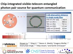
Chipintegrated visibletelecom entangled photon pair source for quantum communication Xiyuan Lu 1 2 Qing Li 1 2 Daron A Westly 2 Gregory Moille 1 2 Anshuman Singh 1 2 Vikas Anant 3 ID: 764539

phys photon mode visible photon phys visible mode telecom pair band source car cavity high flux efficient rev frequency

Share:

Link:

Embed:

Download Presentation from below link

Download Presentation The PPT/PDF document "Chip-integrated visible-telecom entangle..." is the property of its rightful owner. Permission is granted to download and print the materials on this web site for personal, non-commercial use only, and to display it on your personal computer provided you do not modify the materials and that you retain all copyright notices contained in the materials. By downloading content from our website, you accept the terms of this agreement.


Presentation Transcript

Chip-integrated visible-telecom entangled photon pair source for quantum communication Xiyuan Lu ,1, 2 Qing Li,1, 2 Daron A. Westly,2 Gregory Moille,1, 2 Anshuman Singh,1, 2 Vikas Anant,3 and Kartik Srinivasan2 1 2 3 3 dB attenuation distance in single mode fiber 370 nm ( Yb + ion): < 50 m 637 nm (NV -): 300 m780 nm (Rb): 750 m940 nm (QD): 1.5 km1300 nm (O-band): 10 km1550 nm (C-band): 15 km X. Lu et al., Nat. Phys., Jan, 2019. doi: 10.1038/s41567-018-0394-3

Nanophotonic frequency conversion Si (   SiO 2 (   SiN x (   Air/SiO 2 Cladding ( )   Four-wave-mixing Bragg scattering Two pumps at w 1 and w 2 induce an effective grating in the nonlinearity => sets spectral translation range as ±( w 2 - w 1 ) Q. Li et al., Nat. Photon. 10, 406-414 (2016) 2

Visible pump Visible input signalQuantum frequency conversion (QFC) QFC of photon pair sourceQFC of quantum dot Both 980 nm intraband conversionNontrivial for visible-telecom QFC Pump noise, dispersion, pump laser etc. A. Singh et al., under review Q. Li et al., under review Visible pump3

3 dB attenuation distance in single mode fiber 370 nm ( Yb+ ion): < 50 m637 nm (NV-): 300 m780 nm (Rb): 750 m940 nm (QD): 1.5 km1300 nm (O-band): 10 km1550 nm (C-band): 15 kmVisible-telecom photon pair source Most quantum memories are in the visibleVisible photons have limited travel range in optical fibers Motivation: entanglement swapping Entangle remote quantum memories using visible-telecom entangled photon pair sources Requirements Wide-band (visible/telecom) Narrow- linewidth (MHz~GHz)Pure (CAR > 100) Bright (high photon flux)Efficient (sub- mW power)Integrable (on-chip)4Entanglement swapping by time measurement:M. Halder et al. Nat. Phys. 3, 692-696 (2007) A review for photon source: M. D. Eisaman et al., Rev. Sci. Instr. 82, 071101 (2011) Motivation: entanglement swapping

Visible-telecom photon pair source 5 PPLN/PPKTP & filtering/cavity J. Fekete et al., Phys. Rev. Lett.110, 220 502 (2013)C. Clausen et al., New J. Phys. 16, 093058 (2014)O. Slattery et al., Appl. Phys. B 121, 413–419 (2015)D. Rieländer et al., New J. Phys. 18, 123 013 (2016) PPLN/PPKTP Wide-band (visible/telecom)Broadband, external filtering/cavity Pure (CAR > 100) Bright (high photon flux)Power efficient (if cavity is used) Cavity ~ 1 meter, not integrable yet

Visible-telecom photon pair source 6 PPLN/PPKTP & filtering/cavity J. Fekete et al., Phys. Rev. Lett.110, 220 502 (2013)C. Clausen et al., New J. Phys. 16, 093058 (2014)O. Slattery et al., Appl. Phys. B 121, 413–419 (2015)D. Rieländer et al., New J. Phys. 18, 123 013 (2016)PhC fiberC. Söller et al., Phys. Rev. A 81, 031 801 (2010) PhC fiber Wide-band (visible/telecom)Broadband, ~ 1nm CAR low, typical a few 10s Bright (high photon flux)fs laser pulse needed Length ~ 10 cm, already in fiber

Visible-telecom photon pair source 7 PPLN/PPKTP & filtering/cavity J. Fekete et al., Phys. Rev. Lett.110, 220 502 (2013)C. Clausen et al., New J. Phys. 16, 093058 (2014)O. Slattery et al., Appl. Phys. B 121, 413–419 (2015)D. Rieländer et al., New J. Phys. 18, 123 013 (2016) PhC fiberC. Söller et al., Phys. Rev. A 81, 031 801 (2010)Lithium Niobate mm-resonator G. Schunk et al., Optica 2, 773–778 (2015) LiNbO3 mm-resonator Wide-band (visible/telecom) Narrow-band (17 MHz) CAR low, < 20 Bright (high photon flux) Efficient (a few microwatt) Length ~ a few mm, not integrable yet

Visible-telecom photon pair source 8 PPLN/PPKTP & filtering/cavity J. Fekete et al., Phys. Rev. Lett.110, 220 502 (2013)C. Clausen et al., New J. Phys. 16, 093058 (2014)O. Slattery et al., Appl. Phys. B 121, 413–419 (2015)D. Rieländer et al., New J. Phys. 18, 123 013 (2016)PhC fiberC. Söller et al., Phys. Rev. A 81, 031 801 (2010)LiNbO3 mm-resonatorG. Schunk et al., Optica 2, 773–778 (2015) PhC fiber Wide-band (visible/telecom) Broadband, need filtering/cavity CAR low, typical a few 10s Bright (high photon flux) High power pump/pulse neededLength ~ 10 cm LiNbO3 mm-resonator Wide-band (visible/telecom)Narrow-bandCAR low, typical a few 10s Bright (high photon flux) Efficient (sub- mW power) Length ~ a few mm, not integrable yet PPLN/PPKTP Wide-band (visible/telecom) Broadband, need filtering/cavity Pure (CAR > 100) Bright (high photon flux) Efficient (sub- mW power) Cavity ~ 1 meter, not integrable yet No nanophotonic source for our intended applications yet!

Silicon nitride nanophotonics/photon pair source 9 Silicon nitride nanophotonicsFrequency combT. J. Kippenberg, et al., Science, 332, 555 (2011)Y. Okawachi et al., Opt. Lett. 36, 3398–3400 (2011) Q. Li et al, Optica 4, 193–203 (2017)M. Karpov, Nat. Commun. 9,1146 (2018)D. T. Spencer et al., Nature, 557, 81-85 (2018)High dimensional frequency-bin M. Kues et al., Nature, 546, 622-626 (2017) P. Imany et al., Opt. Express, 26, 1825-1840 (2018) Harmonic generation, QFC etc. Q. Li et al., Nat. Photon. 10, 406-414 (2016)J. S. Levy et al., Opt. Express, 19, 11415-11421 (2011) Silicon nitride photon pair source S. Ramelow et al., arXiv:1508.04358 (2015)J. A. Jaramilllo -Villegas et al., IPRSN, IW3A.2 (2016)Limited to telecom band and inferior to Si Not very pure (CAR < 100)Q. Li et al., under review (980 nm Pair + QFC) Silicon nitride /silicon dioxideMany groups developing this platform Columbia: Lipson/Gaeta; Purdue: Qi/Weiner; EPFL: Kippenberg; Chalmers: Torres-Company, etc. Wide transparency window (300 nm to 6 m m) Large n 2 (10x that of SiO 2 ); ; .   Review: D. J. Moss et al., Nat. Photon. 7, 597-607 (2013 ) Wide-band pair source surpassing Si! This CAR has room to improve! Si (   SiO 2 (   SiN x (   Air/SiO 2 Cladding ( )  

Device scheme 10 Single Fundamental Mode Family (SFMF) engineering Coupling DispersionX. Lu et al., Nat. Phys., Jan, 2019. doi:10.1038/s41567-018-0394-3

Frequency-matching Interacting modes need to be frequency matched 2 wp=wi + wsDispersion engineering so that overall mismatch is within a cavity linewidthPhase-matchingFor single mode family operation, interacting modes are phase matched when 2bp=bi + bs => 2mp=mi + msResonator enhancement High loaded Q for the three modes Mode overlap for the three modesResonator-waveguide coupling Efficient injection of pump mode Efficient extraction of signal and idler modeSingle fundamental mode family (TE1)Selective mode splitting Efficient four-wave mixing in a microresonator   | TE1 mode family   11 Whispering gallery mode number w frequency   Frequency-matching Interacting modes need to be frequency matched 2 w p = w i + w s Dispersion engineering so that overall mismatch is within a cavity linewidth Phase-matching For single mode family operation , interacting modes are phase matched when 2 b p = b i + b s => 2 m p = m i + m s Resonator enhancement High loaded Q for the three modes Mode overlap for the three modes Resonator-waveguide coupling Efficient injection of pump mode Efficient extraction of signal and idler mode Single fundamental mode family (TE1) Selective mode splitting

  Coherent geometric modulation to split and only split targeted modes For example, the inside ring radius is modulated by   The mode splitting is orthonormal and can be estimated by   Coherent geometric modulation to split targeted modes only For example, the inside ring radius is modulated by   The mode splitting is orthonormal and can be estimated by Selective mode splitting 12 X. Lu et al., Appl. Phys. Lett . 105, 151104 (2014)

Selective mode splitting 13

Frequency-/Phase-matching, StFWM , and SpFWM ms = 443ls = 668.3789 nmmp = 303lp = 933.6211 nm m i = 163l i = 1547.8960 nm Q = 1.52 x 10⁵ Q = 1.04 x 10 6 Q = 1.93 x 10⁵ Dw /2 p = (0.16 ± 0.04) GHz < 1 GHz Phase-matching Choose modes with   Frequency-matching Adjust geometry for   StFWM Pump/telecom input, visible out SpFWM photon spectra 14 m s = 443 m i = 163 m s = 444 m i = 162 Dw /2 p = 3.86 GHz

Pair flux and CAR, power dependence 15 Photon pair characteristics Wide-band: Over an octave, 668/1548 nmNarrow-linewidth: < 1 GHzPure (CAR > 100)Bright (high photon flux)Efficient (sub-mW power)Integrable (on-chip) P( μ W) N(Pairs/s) CAR 46 4800 2200 146 62000 423 ~22 1200 3780

Pair flux and CAR, a comparison 16 Visible-telecom photon pair source PPLN/PPKTP & filtering/cavity[12] J. Fekete et al., Phys. Rev. Lett.110, 220 502 (2013)[9] C. Clausen et al., New J. Phys. 16, 093058 (2014)[13] O. Slattery et al., Appl. Phys. B 121, 413–419 (2015) [14] D. Rieländer et al., New J. Phys. 18, 123 013 (2016)PhC fiber[10] C. Söller et al., Phys. Rev. A 81, 031 801 (2010)LiNbO 3 mm-resonator[11] G. Schunk et al., Optica 2, 773–778 (2015) Comparison Among the best for overall performance considering both flux and CAR Record CAR = 3780 at ~N = 5 pairs/sRecord N = 18400 pairs/s, with CAR = 27The high flux regime is perhaps more useful!The first nanophotonic device for narrow-band visible-telecom photon pair sourceA comparison to previous sources Detected pair flux versus CARPower is not the most critical measure

Visible-telecom time-energy entanglement 17

Tailoring the source for different systems 18 Ability to tune the visible wavelength to match different systems by changing the parameters in the nanophotonic deviceChange the device ring width (colors)Change the pump mode (x-axis)Change the device thickness (635/740 nm plato, not shown here)

Future work 19 Entanglement swapping between two pair sources Two sources identical at telecom photon spectrumConnection to visible quantum memory (need collaboration)Photon pair source for Pr3+:YSO (606 nm)Photon pair source for NV- (637 nm) and SiV (737 nm)

Acknowledgements Qing Li Postdoc Prof. at CMU nowDaron WestlyResearch scientistAnshuman SinghPostdoc Gregory MoillePostdoc Kartik Srinivasan Project leaderVikas Anant Photon Spot NIST on a chip 20

21