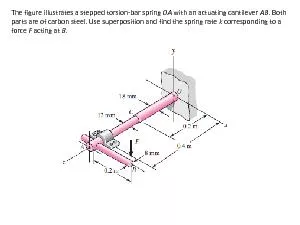
/
The figure illustrates a stepped torsion The figure illustrates a stepped torsion

The figure illustrates a stepped torsion - PDF document

yoshiko-marsland
yoshiko-marsland . @yoshiko-marsland
Follow
876 views
Uploaded On 2015-08-11

The figure illustrates a stepped torsion - PPT Presentation

bar spring OA with an actuating cantilever AB Both parts are of carbon steel Use superposition and find the spring rate k corresponding to a force F acting at B The steel curved bar ID: 104998

- bar spring with

Share:

Link:

Embed:

Download Presentation from below link

Download Pdf The PPT/PDF document "The figure illustrates a stepped torsion" is the property of its rightful owner. Permission is granted to download and print the materials on this web site for personal, non-commercial use only, and to display it on your personal computer provided you do not modify the materials and that you retain all copyright notices contained in the materials. By downloading content from our website, you accept the terms of this agreement.


Presentation Transcript

The figure illustrates a stepped torsion - bar spring OA with an actuating cantilever AB . Both parts are of carbon steel. Use superposition and find the spring rate k corresponding to a force F acting at B . The steel curved bar shown has a rectangular cross section with a radial height h = 6 mm, and a thickness b = 4 mm. The radius of the centroidal axis is R = 40 mm. A force P = 10 N is applied as shown. Find the vertical deflection at B . Use Castigliano’s method for a curved flexural member , and since R/h 10, do not neglect any of the terms. For the steel wire form shown, use Castigliano’s method to determine the horizontal reaction forces at A and B and the deflection at C . A rectangular aluminum bar 10 mm thick and 60 mm wide is welded to fixed supports at the ends, and the bar supports a load W = 4 kN , acting through a pin as shown. Find the reactions at the supports and the deflection of point A . The steel beam ABCD shown is supported at C as shown and supported at B and D by shoulder steel bolts, each having a diameter of 8 mm. The lengths of BE and DF are 50 mm and 65 mm, respectively . The beam has a second area moment of 21(103) mm4. Prior to loading, the members are stress - free. A force of 2 kN is then applied at point A. Using procedure 2 of Sec. 4 – 10, determine the stresses in the bolts and the deflections of points A , B , and D . Link 2, shown in the figure, is 25 mm wide, has 12 - mm - diameter bearings at the ends, and is cut from low - carbon steel bar stock having a minimum yield strength of 165 MPa . The end - condition constants are C = 1 and C = 1 . 2 for buckling in and out of the plane of the drawing, respectively. ( a ) Using a design factor nd = 4, find a suitable thickness for the link. ( b ) Are the bearing stresses at O and B of any significance?