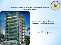
Prepared by Nizar Abed AlMajeed Salameh Mohamed Khaled AbuAl Huda Supervisor Dr Imad AlQasem CHAPTER ONE INTROUCTION The project is a structural analysis and 3DDynamic design of an office building in Ramallah city known as ALHuriya which consists of a seven stor ID: 409001
Download Presentation The PPT/PDF document "3D-Dynamic design for reinforced versus ..." is the property of its rightful owner. Permission is granted to download and print the materials on this web site for personal, non-commercial use only, and to display it on your personal computer provided you do not modify the materials and that you retain all copyright notices contained in the materials. By downloading content from our website, you accept the terms of this agreement.
Slide1
3D-Dynamic design for reinforced versus prestress concrete for Al-Huriya building
Prepared by
Nizar Abed Al-Majeed Salameh
Mohamed Khaled Abu-Al Huda
Supervisor
Dr. Imad Al-QasemSlide2
CHAPTER ONEINTROUCTIONThe project is a structural analysis and 3D-Dynamic design of an office building in Ramallah city, known as AL-Huriya, which consists of a seven stories, with 3.5 height except the first floor with 4m story height.
The building will be first designed under a static load, after that we will study the building for dynamic , finally a prestress concrete will be used to design the building to compare it with the reinforcement concrete, to conclude many factors that should be taken into consideration in designing any structure. These include economic factors , durability and the safety of its inhabitants.Slide3
System
Part
F’c
fy
Reinforced
Concrete
Slab
250 kg/cm24200 kg/cm2Beams250 kg/cm24200 kg/cm2Columns500 kg/cm24200 kg/cm2Footings250 , 500 kg/cm24200 kg’cm2Prestress Concreteslab6000Psi243KsiColumns500 kg/cm24200 kg/cm2Footings250 , 500 kg/cm24200 kg/cm2
Materials
Live load0.4ton/m2Super imposed load0.3ton/m2
LoadsSlide4
CHAPTER TWO
SLAB Slide5
One way solid slab is used only as slab systemUse slab thickness of 17cm , according to deflection requirement
In design phase of the slab, there are two strip(1m) taken as a
model.
W
u
=1.51
15@3.75m
6@3.75mWu=1.51Strip IStrip IILoads distribution Slide6
Strip I
Use 4Ф12mm for negative and positive moment
Moment distribution
Strip IISlide7
CHAPTER THREEBEAMSBeams in this part of the project will be designed using reactions from beam model in SAP2000
.The girder system is used to design the building, and all of the beams are dropped; multi span and large space beams are used in all floors.
The system of the building consist of a four beams group (B1, B2, B3, B4)And a two group of girders (G1, G2).Slide8Slide9
Design for Moment
Final Results
Positive Moment
Negative Moment
Exterior spans
Interior span
Interior supports
BeamsDimensionsMnΡAsMnρAsMnρAsB130x8065.610.010225.451.310.00337.6258.760.009122.90B250x90168.82
0.0112
58.883.440.003314.70152.170.011349.06
B3
50x90
183.76
0.0141
63.78
-
-
-
129.34
0.0094
44.16
B4
60x100
263.26
0.0133
78.50
-
-
-
-
-
-
Final Results
Positive Moment
Negative Moment
Exterior spans
1st interior spans
2nd interior spans
1st interior supports
2nd interior supports
GirdersDimensionsMnρAsMnρAsMnρAsMnρAsMnρAsG150x90164.240.012353.9751.99.003619.63117.93.008539.25163.620.012353.97141.80.010440.06G290x100384.780.0129112.54219.22.006964.3162.57.003332.15411.270.0141120.58209.440.006656.27
Moment Design
Parameter
Dimensions
Mn
As
Vn
Vc
Vs
Av
S
Units
cm
ton.m
cm
2
ton
ton
ton
cm
2
cmSlide10
Shear DesignDesign for Shear
Final Results
Exterior spans
Interior span
Beams
Dimensions
Vn
VcVsAvSVnVcVsAvSB130x8031.74618.85512.8901.573521.25018.8552.3951.5735B250x9080.1035.6144.493.14255435.6118.393.1440B3
50x90
77.2235.6141.613.142525.1035.6114.8753.14
40
B4
60x100
69.69
47.76
21.43
3.14
45
-
-
-
-
-
Final Results
Exterior spans
1
st
interior spans
2
nd
interior span
Girders
Dimensions
Vn
Vc
Vs
Av
S
Vn
VcVsAvSVnVcVsAvSG150x9093.4935.6157.883.142075.4435.6139.833.142592.2635.6156.653.1420G290x100229.171.64157.43.145202.671.641313.14599.5271.6427.883.1445Slide11
Final Results
For positive moment (span)
Negative moment (support)
Beam
Exterior
1
st
interior2nd interior1st interior2nd interiorB110Φ183Φ18-9Φ18-B212Φ253Φ25-10Φ25-B313Φ25--9Φ25-B416Φ25----G111Φ254Φ258Φ2511Φ25
10Φ25
G214Φ328Φ324Φ3215Φ327Φ32Slide12
CHAPTER FOURCOLUMNSsixteen columns having a rectangular section, and
eight columns having a circular section, will be designed.
All the columns in this project are classified into two groups depending on the ultimate axial load and the shape.
The ultimate axial load on each column is from the Reaction of beams
Columns number
Ultimate load(ton)
Ultimate loads from seven stories(ton)
C1144.241009.68C260.96426.72C3179.181254.26C4452.713168.97C5287.652013.55Group (1)C1,C2,C3RectangularGroup (2)C4,C5Circular Slide13Slide14
Summary of result
Group
Pu
(ton)
Dimensions(h*b)(cm) spirally (D)(cm)
ρ
As(cm2)
# of barsShear reinforcementI1254.26100*500.015276.0416 Φ25mm4 Φ10mm/30cmII3168.97Spiral, D=1000.0206267.4134 Φ32mmΦ10mm(spirally)Final ResultsSlide15
CHAPTER FIVEFOOTING In this chapter the footing will be designed, all footings in this part of the project will be isolated (single) footings.
The design will depend on the total axial load carried by each column.
Group
ID
Columns
included
Loads (ton)
Dead loadLive loadF1C1,C2,C3726203F2C4,C51698504The footings are classified into two groups Slide16Slide17
Flexure Design
X-Y Direction Steel Design
Mu =
107.12
ton.m
ρ =0.0023 As =25.62cm2As min =21.6cm2 Use As = 25.62cm2 Bar Diameter25mm # of Bars Needed6
Spacing16.67cmGroup F1 Design
Use
Main Steel
6ф25/ m
Or
1ф25/16cm
Shrinkage Steel
5ф25/20cmSlide18
Flexure Design
X-Y Direction Steel Design
Mu =
274.80
ton.m
ρ =0.0025 As =43.24cm2As min =32.4cm2 Use As = 43.24cm2 Bar Diameter32mm # of Bars Needed6
Spacing16.67cmGroup F2 Design
Use
Main Steel
6ф32/ m
Or
1ф32/16cm
Shrinkage Steel
5ф32/20cmSlide19
FootingID
Footing Dimentions
(m)
Bottom Steel
Top Steel
Width
Length
ThicknessLong dir.Short dir.Long dir.Short dir.F14.65.11.26ф25/ m6ф25/ m3ф25/20cm3ф25/20cmF27.457.451.86ф32/ m 6ф32/ m 3ф32/20cm3ф32/20cmFinal ResultsSlide20
Ground Beam DesignSlide21
Dimensions
Bottom & Top Steel
G.BWidth(m)
Depth(m)
exterior
interior
Support
G.B I0.40.77Ф205ф187Ф25G.B II0.50.759Ф255ф1810ф25Final ResultSlide22
Static vs. Dynamic analysis
Our representative element will be the bending moment at the mid span of the interior span in the 2nd frame for each model.
We will take model for three stories , seven stories
and ten
stories then read the moment due to dead load and live load.
Moment due
Three Stories
Seven StoriesTen StoriesAverageLive Load9.79.529.729.549.829.66Dead Load25.3824.9325.4624.9925.7725.31As the result shows, the common practice is correct for interior floors in static analysisStatic analysisSlide23
Columns ComparisonOur representative element will be the axial force due to
live load .
We will take model for three stories , seven stories and ten stories
,then
read
the axial force for corner , edge and interior columns in the bottom of each model.
SAP 2000 Analysis Results
Axial Force ForThree StoriesSeven StoriesTen StoriesCorner Column43.32 ton105.98 ton157.76 tonEdge Column86.68 ton207.98 ton302.27 tonInterior Column241.98 ton485.37 ton676.77 tonSlide24
Internal Col.
Edge Col.
Corner Col.
Tributary
areaSlide25
Tributary area ResultsLive Load = 0.4 ton/m2
Axial Force ForThree Stories
Seven StoriesTen StoriesCorner Column
43.03 ton
100.41 ton
143.44 ton
Edge Column
93.66 ton218.53 ton312.19 tonInterior Column187.31 ton 437.06 ton624.38 tonSlide26
Using SAP 2000 Software
# of StoriesT(sec)Mass Participation Ratio
DirectionOne
0.534228
0.995042
X-Direction
0.435512
0.996652Y-DirectionThree1.0991290.965566X-Direction0.8824230.970756Y-DirectionSeven2.0924260.932716X-Direction1.657030.938386Y-DirectionTen2.8069960.913832X-Direction2.214390.91895Y-DirectionSeven+Elcento2.0924260.932716X-Direction1.657090.938386Y-DirectionDynamic AnalysisSlide27
CHAPTER SEVENPRESTRESS CONCRETEPrestress concrete is not a new concept, it’s backing to 1872. (Jackson), an engineer from California, patented
prestressing system that used a tie rod to construct beams or arches from individual blocks.
The most practical development in prestressed concrete occurred from (1920 – 1960).
Introduction
We will design the
prestress
building for gravity loads only, and the punching shear excluded from this study.(ACI units is used)Slide28
Material properties and loadsMaterial properties:-f’c
=6000 Psi f’ci
= 4200 Psffp
u
= 270
Ksi
fpy =243 Ksifpe= 159 Ksi fy = 60000 PsiUse strands = 1.0 inch. Pe= 257597 IbLoads:-live load (LL) = 80 PsfSuper Imposed Load (SID) = 60 PsfSlide29
Slab thickness = Slab thickness =
= 13.13 inches.
Take slab thickness = 13.5 inches.Slide30
Check stresses:-1) check allowable stresses for the prestressing force and the slab own weight.
2) Check the ultimate strength .Slab Design for
prestress system Slide31
Columns design for Prestress system
Sixteen columns having a rectangular section, and eight columns having a circular section, will be designed.
All the columns in this project are classified into two groups depending on the ultimate axial load and the shape.
The ultimate axial load on each column is from the
Tributary area.
Columns number
Ultimate loads from seven stories(ton)C1606.06C21119.30C31210.70C41725.00C52240.00Group (1)C1,C2,C3Group (2)C4,C5sSlide32
Summary of result
Group
Dimensions(h*b)(cm) spirally (D)(cm)
ρ
As(cm2)
# of bars
Shear reinforcement
I95*550.012328.168 Φ22mm4 Φ10mm/25cmIISpiral, D=900.01423
128.68
16 Φ32mmΦ10mm(spirally)
Final ResultsSlide33
Footing design for prestress system
All footings in this part of the project will be isolated (single) footings.
The design will depend on the total axial load carried by each column.
The footings are classified into two groups
Group
ID
Columns
includedLoads (ton)Dead loadLive loadF1C1,C2,C3694236F2C4,C5
1284
437Slide34
Group F1 DesignFlexure Design
X-Y Direction Steel Design
Mu =
108.34
ton.m
ρ =0.0020 As =24.34cm2
As min =
23.4cm2
Use As =
24.34
cm
2
Bar Diameter
25
mm
# of Bars Needed
5
Spacing
20
cm
Use
Main Steel
5ф25/ m
Or
1ф25/20cm
Shrinkage Steel
5ф25/20CmSlide35
Group F2 DesignFlexure Design
X-Y Direction Steel Design
Mu =
222.97
ton.m
ρ =0.0031 As =42.71cm2As min =27cm2 Use As = 42.71cm2 Bar Diameter28mm # of Bars Needed7 Spacing14.29cmUse
Main Steel
7ф28/ mOr
1ф28/14cm
Shrinkage Steel
5ф28/20cmSlide36
FootingIDFooting Dimentions
(m)
Bottom SteelTop Steel
Width
Length
Thickness
Long dir.
Short dir.Long dir.Short dir.F14.655.051.35ф25/ m5ф25/ m3ф25/20cm3ф25/20cmF26.66.61.57ф28/ m7ф28/ m3ф28/20cm3ф28/20cmFinal Results