/
The dc and noise specifications for in-amps differ slightly from conve The dc and noise specifications for in-amps differ slightly from conve

The dc and noise specifications for in-amps differ slightly from conve - PDF document

anderson
anderson . @anderson
Follow
343 views
Uploaded On 2021-01-05

The dc and noise specifications for in-amps differ slightly from conve - PPT Presentation

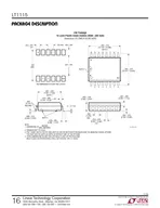
Rev0 1008 WK AD623 AD627 AD8220 JFET input railtorail output AD8221 AD8223 and AD8224 Absolute value laser wafer trimming allows the user to program gain accurately with this si ID: 826707

gain amp input offset amp gain offset input voltage analog devices error output accuracy isbn resistor drift errors frequency

Share:

Link:

Embed:

Download Presentation from below link

Download Pdf The PPT/PDF document "The dc and noise specifications for in-a..." is the property of its rightful owner. Permission is granted to download and print the materials on this web site for personal, non-commercial use only, and to display it on your personal computer provided you do not modify the materials and that you retain all copyright notices contained in the materials. By downloading content from our website, you accept the terms of this agreement.


Presentation Transcript

Rev.0, 10/08, WK The dc and noise speci
Rev.0, 10/08, WK The dc and noise specifications for in-amps differ slightly from conventional op amps, so some , AD623, AD627AD8220 (JFET input, rail-to-rail output), AD8221, , AD8223, and AD8224Absolute value laser wafer trimming allows the user to program gain accurately with this single resistor. The absolute accuracy and temperature coefficient of this resistor directly affects the in-amp gain accuracy and drift. Since the external resistor will never exactly match the internal thin film resistor tempcos, a low TC (/°C) metal film resistor should be chosen, preferably 1,000, or 1 to 10,000, many , AD624, the gain-set resistors are internal, well matched, and the device gain accuracy and gain drift specifications include their milar to the externally gain-programmed . AD8250, AD8251, and AD8253 have both pin and software programmable gains and are (BR Grade) have very low factory trimmed gain errors, with its maximum error of 0.02% at G = 1 and 0.15% at MT-064allow the u

ser to set the gain exactly, the tempera
ser to set the gain exactly, the temperature coefficients of the external resistors and the temperature differences between individual resistors within the network all contribute to the overall gain error. If the data is eventually digitized and presented to a digital processor, it may measuring a known reference voltage and then multiplying by a constant. Gain nonlinearity is defined as the maximum deviation frversus input. The straight line is drawn between the end-points of the actual transfer function. Gain nonlinearity in a high quality in-amp is usually 0.01% (100 ppm) or less, and is relatively insensitive to gain over the recommended gain range. INPUT OFFSET VOLTAGE AND BIAS CURRENT ERRORS of an in-amp consists of two components (see Figure 1 below). amp by the gain G. ~OSOIN-AMPGAIN = GIOS= IB+–IB–OFFSET (RTI) =OFFSET (RTO) =OSO OUTVSIG2VSIG2VSIG2Figure 1: In-Amp Offset Voltage Model At low gains, output offset voltage is dominant, output offset voltage drift is nor

mally specified as drift at G = 1 (where
mally specified as drift at G = 1 (where input effects are insignificant), while input offset voltage drift is(where output offset effects are negligible). The total output offset error, referred to the input (RTI), is equal to V/G. In-amp data sheets may specify VOSO Page 2 of 5 MT-064may also produce offset errors in in-amp circuits (Fig. 1, agai, is unbalanced by an amount, , (often the case in bridge circuits), then there is (assuming that I). This error is reflected to thCOMMON-MODE REJECTION AND POWER SUPPLY REJECTION ERRORS In-amp frequency. Analog Devices specifies in-amp CMR for a 1 k source impedance unbalance at a ng the common mode voltage, V in-amp as a function of frequency, with a 1 ksource impedance imbalance. AD620 In-Amp Common-Mode Rejection (CMR) Versus Frequency For 1 kand frequency. For in-amps, it is customary to specify the sensitivity to each power supply separately, as shown in Figure 3 below deviation from nominal by the power Page 3 of 5 MT-064 POSITIVE SU

PPLYNEGATIVE SUPPLYRejection (PSR) Vers
PPLYNEGATIVE SUPPLYRejection (PSR) Versus Frequency quencies, decoupling capacitors are required on both power pins to an in-amp. Low inductance ceramic capacitors (0.01 to 0.1 µF) are appropriate for high frequencies. Low ESR electrolytic capacitors should also be located at TOTAL IN-AMP DC ERROR BUDGET Now that all dc error sources have been accounted for, a worst case dc error budget can be ces to the in-amp input, as is ERROR SOURCEGain Accuracy (ppm)Gain Nonlinearity (ppm)Input Offset Voltage, VOutput Offset Voltage, VInput Bias Current, I, Flowing in Input Offset Current, I, Flowing in RCommon Mode Input Voltage, VPower Supply Variation, RTI VALUEGain Accuracy ×FS InputGain Nonlinearity ×FS InputOSIOSO÷CMRR÷PSRR errors can be referred to the in-amp output (RTO), by simply multiplying the RTI error by the in-amp gain. Page 4 of 5 Page 5 of 5 REFERENCES Hank Zumbahlen, Basic Linear Design, Analog Devices, 2006, ISBN: 0-915550-28-1. Also available as Linear Circuit Design Handbook,

Elsevier-Newnes, 2008, ISBN-10: 0750687
Elsevier-Newnes, 2008, ISBN-10: 0750687037, ISBN-13: 978-0750687034. Chapter 2. Walter G. Jung, Op Amp ApplicationsAnalog Devices, 2002, ISBN 0-916550-26-5, Also available as Op Amp Applications Handbook, Elsevier/Newnes, 2005, ISBN 0-7506-7844-5. Chapter 2. Charles Kitchin and Lew Counts, A Designer's Guide to Instrumentation Amplifiers, 3 Edition, Analog Devices, 2006. Copyright 2009, Analog Devices, Inc. All rights reserved. Analog Devices assumes no responsibility for customer product design or the use or application of customers’ products or for any infringements of patents or rights of others which may result from Analog Devices assistance. All trademarks and logos are property of their respective holders. Information furnished by Analog Devices applications and development tools engineers is believed to be accurate and reliable, however no responsibility is assumed by Analog Devices regarding technical accuracy and topicality of the content provided in Analog Devices Tutorials.