/
P09503 P09503

P09503 - PowerPoint Presentation

calandra-battersby
calandra-battersby . @calandra-battersby
Follow
381 views
Uploaded On 2017-07-29

P09503 - PPT Presentation

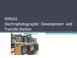
Electrophotographic Development and Transfer Station Team Members Name Discipline Role David Schwartz ISE Team Lead Warning Signs Ruth Gay ME Paper Delivery System Phillip Lopez ME ID: 574103

transfer system systems current system transfer current systems design development days user control printing ozone complete warning signs phase

Share:

Link:

Embed:

Download Presentation from below link

Download Presentation The PPT/PDF document "P09503" is the property of its rightful owner. Permission is granted to download and print the materials on this web site for personal, non-commercial use only, and to display it on your personal computer provided you do not modify the materials and that you retain all copyright notices contained in the materials. By downloading content from our website, you accept the terms of this agreement.


Presentation Transcript

Slide1

P09503Electrophotographic Development and Transfer StationSlide2

Team Members

Name

Discipline

Role

David Schwartz

ISE

Team Lead – Warning Signs

Ruth Gay

ME

Paper Delivery System

Phillip Lopez

ME

Ozone Filter

Dan Summers

ME

ME Support

Rachel Chrash

EE

LED Exposure System

Min-Shi Hsiao

EE

PC Potential Measurement

Andrew Kearns

EE

Transfer Drum Speed Measurement, Camera System

Sasha Oliver

CE

User InterfaceSlide3

Project BackgroundProject FamilyPrinting and Imaging Systems Technologies Track

Customer

Print Research and Imaging Science Modeling Laboratory (PRISM

)

The Print Research and Imaging Systems Modeling lab will serve as a conduit between industry and academia, working to evaluate and anticipate the print systems research needs of printer and printing product companies, and directing relevant projects to researchers and students in the areas of Printers & Displays, Color Science, Vision Science, Systems Engineering, and Printing.

Contact

: Dr. Marcos

Esterman

– Associate Professor, Industrial and Systems Engineering Slide4

Project DescriptionWorking Electrophotographic station to

vary both the printing material and the printing process parameters as to better understand and improve the performance of similar printing systems

.

End Users

PRISM Lab

Center for Imaging Science

Deliverables

An

inventory and status of current sub-systems, including needed support systems.A working Electrophotographic Station.Demonstrably improved device safety.An improved user interface (includes control and display functions)Device documented for use, maintenance and upgrade of the device (User & Lab Technician Manual)Demonstrably Improved Sensing and Control SubsystemSlide5

What is Electrophotography?Electrophotography

is base technology that is used in many modern day copiers and printers

Six Step Process to transfer an electrostatic image to a final printed page

Charging

Exposure

Development

Transfer

Fusing

CleaningP09503 only includes the first fourSlide6

Electrophotographic and Development StationSlide7

Electrophotographic and Development Station

Charging

Exposure

Development

TransferSlide8

ConsultantsRIT Faculty

Professional

Jonathon

Arney

,

Ph.D

Center

for Imaging

SciencePhysical & Optical MeasurementsSusan Farnand, Ph.DCenter for Imaging ScienceColor and Vision ScienceJohn D. WellinMechanical EngineeringControl SystemsMarcos Esterman, Ph.DIndustrial and Systems EngineeringProduct & Process Development

Bill Nowak – Xerox

Principle Engineer

Motion and Quality Systems

Gregory Miller – Kodak

Software EngineerSlide9

Customer Needs & Functional Diagram1. Is Operational

2. Is Safe

3. Minimize user Intervention

4. Can Monitor Key Process Parameters

5. Can operate and monitor machine from one interface

6. Easy to learn to

useSlide10

Ozone Fan/Filter AssemblyReduce and Secure Ozone Test Stand

Ozone hazardous to humans if exposed to enough

Law states maximum ozone in A/C Space is 0.05

ppm

>0.200

ppm

increases risk of health issues

Two Options

Verify current system or Implementation of further improvement to control Ozone LevelsSlide11

Monitoring Potential on PhotoconductorMonitoring potential of photosensitive material will help characterize exposure input noise source

Charge

v.

Exposure

plot after

measurement can be viewed

Dark Decay Research PossibleSlide12

LED Exposure SystemLED Print Heads used in copiers and printers to expose Photosensitive Material are commonly used

LED Exposure system to replace current incandescent system

Advantages

More versatile and reliable light source

Low Power Consumption

Longer Bulb Life

No potential for overheat

Inexpensive to replaceSlide13

Paper Delivery SystemExisting roller system requires manually catching paper after application of toner from roller

Possible risks of manual handling

Shock Short from High Voltage Roller

Pinch Point of Rollers and Pneumatics

Marred Image QualitySlide14

High Visibility Warning SignsPurpose of warning signsAlert user to specific hazard

Identify how hazard can be avoided

Current signs do not accomplish this

Remove current warning signs

Replace with ISO designed signs

Add new ISO signs where neededSlide15

Camera SystemPurpose is to gain understanding of how image is developed onto photoreceptive material

Photoreceptive material imaged after development and before transferSlide16

Transfer Roller Speed MeasurementSpeed of transfer roller critical to timing control and image qualityNeed to assure that transfer drum rotates at the same speed as the moving photoconductor as to not elongate/condense the image

Need to assure that the transfer roller will be in the proper position for transfer to paperSlide17

Labview Control InterfaceCurrent control system is done via PLCBetter solution needed to replace current system with a new user friendly interface

Automatic and Manual Setting

Labview

uses dataflow programming to define inputs/outputs and execution sequence of the virtual instrument

Connect devices directly to DAQ to allow for more robust controlSlide18

Technical Risk AssessmentData Acquisition Implementation – Coding Complications / Integration with SubsystemsMitigation: Primary Focus During SD II

Obtaining Optimal Parameters (>10) for EP Process

Mitigation: Experimental Design to optimize parameters, Consult with Xerox and CIS

Toner and Developer Contamination

Mitigation: Implement Air Filtration System and Warning SignsSlide19

Current State of DesignCurrent design meets all feasible customer needsCustomer understands unfeasible needs

Current design meets all engineering specifications

Budget = $1500

Total Expenditures < $900

Schedule

On Schedule, no Design Delays Slide20

Product Development Process PhasePhase 0: PlanningCompleted

Phase 1: Concept

Development

Completed

Phase 2: System Level

Design

Completed

Phase 3: Detailed Design

CompletedPhase 4: Testing and RefinementWill begin in SD IISlide21

Senior Design II Schedule and Milestones

Milestone

Duration

Completion Date

User Manual Complete

14 Days

12/18/08

Ozone Decision

39 Days1/9/09PC Potential Measurement Device Complete35 Days2/10/09LED Complete29 Days2/2/09Paper Delivery System Complete

43 Days

2/20/09

Warning Signs Complete

18 Days

1/7/09

Labview

/Camera/Speed Complete

73 Days

3/25/08Slide22

Questions

Related Contents

Next Show more