/
Radiant Floor Systems Coupled with Geothermal Heat Pumps Radiant Floor Systems Coupled with Geothermal Heat Pumps

Radiant Floor Systems Coupled with Geothermal Heat Pumps - PowerPoint Presentation

cheryl-pisano
cheryl-pisano . @cheryl-pisano
Follow
389 views
Uploaded On 2017-06-04

Radiant Floor Systems Coupled with Geothermal Heat Pumps - PPT Presentation

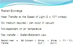
By Brian Urlaub Enertech Global Why are you here Hopefully so you dont end up with something like this Basic components of a waterwater amp combo geothermal heat pump system Tips on proper installation of a hydronic geothermal system ID: 555859

heat water load unit water heat unit load system side hydronic design w2w amp heating insulation tank floor temp

Share:

Link:

Embed:

Download Presentation from below link

Download Presentation The PPT/PDF document "Radiant Floor Systems Coupled with Geoth..." is the property of its rightful owner. Permission is granted to download and print the materials on this web site for personal, non-commercial use only, and to display it on your personal computer provided you do not modify the materials and that you retain all copyright notices contained in the materials. By downloading content from our website, you accept the terms of this agreement.


Presentation Transcript

Slide1

Radiant Floor Systems Coupled with Geothermal Heat PumpsByBrian Urlaub, Enertech GlobalSlide2

Why are you here?Hopefully so you don’t end up with something like this!Slide3
Slide4
Slide5
Slide6
Slide7

Basic components of a water-water & combo geothermal heat pump system.Tips on proper installation of a hydronic geothermal systemLimitations of a hydronic geothermal systemSome design considerations of the systemPiping options for the load sideControl options for the hydronic system

What are we going to cover?Slide8

Design water temp won’t heat space.Insulation generally is the culpritHeat pump is locking out on HP.

Waterflow

,

Waterflow

,

Waterflow

!

To much load side antifreeze?

Controls, Controls, Controls!

High bill complaints.

Low loop temps, could be a multitude of reasons!

Running system at max 120F temps all season.Design of the system must meet the expectations of the customer, and it is your job to install and verify your system will do the job!

What have the problems been?Slide9

What will be my design max water temp?What will be my design min water temp?Will I have a supplemental or backup system?If so, how will it be piped and controlled?What is the heat distribution system?High mass floors - concrete

Low mass floors – staple up

Radiation – high or low temp

Am I doing chilled water for cooling?

Do I have areas that need antifreeze?

Who is doing the insulation? What is it?

What type of floor coverings do I have?

Questions to ask yourself?Slide10

Doing an accurate load calculation is priority number 1 including radiant design!This will dictate your supply water temp and flow rates of the system.Knowing the building materials, insulation values, floor coverings, etc. is critical.Jobsite verification of building materials and insulation practices (pictures, pictures)This all goes into a successful installation and a happy customer with low energy costs!

Proper design starts with Loads!Slide11

Insulation, Insulation, & InsulationSlide12
Slide13

Floor Coverings & DesignSlide14

Concrete slab with R-5 edge and horizontal.Slide15

Concrete slab with R-10 edge and horizontal.Slide16
Slide17

Staple up tubing with no underneath insulation and carpet for floor covering.Slide18

Staple up tubing with R-10 underneath insulation and carpet for floor covering.Slide19

Staple up tubing w/ HE plates, with R-19 underneath insulation, and low R-value carpet & pad for floor covering.Slide20

Radiant floor tube spacing at 9” o.c. min.Do not mix more than 25% glycol antifreeze on load side of heat pump (preferably 0%)Flow rate through each radiant floor loop to be between .50gpm and .75gpmPipe sizing is critical; flow = BTU’sVariable Speed pumps & zone valves!Insulation values, floor coverings, flow rates, tube sizes, etc. all factor in to calculating system design!

Other RecommendationsSlide21

Water-to-Water Heat Pumps

Energy obtained from or rejected to a ground-coupled source (closed-loop)

Utilized to make domestic hot water

Utilized for hot water hydronic systems

Utilized for chilled water hydronic systems

Optional desuperheatersSlide22

Combination Heat Pump (Triple Function)

Energy obtained from or rejected to a ground-coupled source (closed-loop)

Utilized for hydronic heating applications (no chilled water )

Utilized to heat or cool air in forced air applications

Packaged system

Optional DesuperheaterSlide23

Typical Water-Water System

Load Side

W2W Unit

Source Side

We are going to focus on the Load Side of the System!Slide24

ALL heat pump

hydronic

systems require a buffer tank (well almost ALL).

“Decouples” floor pumping and unit flow requirements.

Usually 1 gallon per 1,000

Btuh

In most cases, controls are the most difficult part of the installation.

Know what you’re getting into!

Design systems for max. water temps of 120F or less for compressor life and efficiency!

Load-side “Guidelines” Slide25

V = T x (Qhp – Qload)/Delta T x 500V = VolumeT = Desired minimum run time (minutes)Qhp = HP Capacity

Qload = Heat flow to load when HP is on

Delta T = Differential set point (10F)

Example = 5 x (52,000 - 0)/10 x 500 = 52

Buffer Tank SizingSlide26

The capacity of the heat pump and depending on the control strategy will determine the amount of storage needed.Hot tank – single set pointUsually 10 gallons/ton or 1gal/1000btu’sDemand controlled – single set pointUsually 6 gallons/ton or 1gal/1500btu’sCombo units buffer should be smaller!

Example = 5-ton (52MBH + hot tank)

5-tons x 10gal/ton = 50gal or 52,000btu/1000= 52gal

Buffer Tank SizingSlide27

Both Source Side and Load Side Coaxial heat exchangers are typically identical

Pressure drop ratings are the same

Flow rates on the load side should be roughly the same as the source side

2.5-3

gpm

per ton

Connection size doesn’t always mean pipe size (unit or pump flange)

Load-side “Guidelines” Slide28

Hydronic radiant systems depend on supplemental heat source:No supplemental heat – up size loop

Direct supplemental heat – same as W/A

Indirect supplemental heat – up size loop

Combo unit systems:

100% radiant – size as you normally would depending on supplemental heat source

Some radiant & some F/A – up size loop

Hydronic

systems will need more loop based on the mass of the system vs. heating air!

Loop Field Sizing “Guidelines”Slide29

Ground Source Heat Pumps using R-410a refrigerant typically can only achieve a maximum load side temperature of 120F ELT. This prohibits the use of this technology with other forms or hydronic heating such as radiators and/or sometimes baseboard radiation.There are new low temp baseboard radiators available that will heat at lower than 120F!

GSHP Max Load Side TempSlide30
Slide31

Design the GSHP system to utilize the lowest water temps possible for proper space heating and highest system efficiency!Things to consider:

- Tube spacing/sizing

- Flow rates

- Insulation

- Floor coveringsSlide32

With the COP of the HP going up as the load water design temp goes down, outdoor reset makes sense as a recommended control strategy.Outdoor reset control will vary the design load temperature based on outdoor temperature. The colder the outside temp, the warmer the load temp.This maximizes the COP of the system.Outdoor reset controlsSlide33

Glycol on Load Side

Water quality is also very important!!!Slide34

Affects of Antifreeze in SystemSlide35

Pipe sizing guidelines

Pipe size

Flow

(

gpm

)

Max P.D.

(FT/100 FT)

Max.

Vel

(FPS)

1/2"

0-2

5.0

2.2

3/4"

2-4

4.4

2.4

1"

4-8

4.8

3.0

11/4"

8-15

4.0

3.3

11/2"

15-24

4.0

3.7

2"

24-45

4.0

4.4

2-1/2"

45-72

4.0

5.0

3"

72-130

4.0

5.7

Notes:

Use with hot water and chilled water closed piping systems

Based on schedule 40 BI or Copper pipeSlide36

Water-Water Unit ApplicationsPressurized piping systemsControls

Combo Unit Applications

Pressurized piping systems

Controls

Heating only

Hydronic

SystemsSlide37

Water-Water Heat PumpBuffer Tank (Pressurized or HSS)Load Side PumpControls (Aquastat)Air PadFlow CenterPressurized

Non-Pressurized

Hose kit

Components of a Water-Water SystemSlide38

TubingFastenersManifoldsFittingsZone pumps/Zone ValvesFlanges (w/ pumps)Hydronic Accessories

Air Eliminator

Expansion Tank

Controls

Zone Control

Pump Relay

Thermostats

Additional Components of SystemSlide39

Heat Only – W2W Unit & HSS

Load Side Pump

Buffer Tank

Aqua-stat

GW Unit

Zone Pumps

Manifolds

Tubing

PT PortsSlide40

Heat Only – W2W Unit

Load Side Pump

Buffer Tank

Aqua-stat

W2W Unit

Flow Center

Zone Pumps

Manifolds

TubingSlide41

Heat Only – W2W UnitSlide42

115F

T1 T2

24V AQUASTAT WITH N/O DRY CONTACTS

THAT WILL CLOSE ON FALL IN TEMP!

HEATING ONLY CONTROLS!

Sensor in tankSlide43
Slide44

Heat Only – W2W Unit w/ HSSSlide45
Slide46

Heat Only – 2stg W2W Unit

Load Side Pump

Buffer Tank

Aqua-stat

W2W Unit

Flow CenterSlide47

Heat Only – 2stg W2W UnitSlide48

Heat Only – 2stg W2W UnitSlide49

Combo Heat PumpThermostat (Forced Air)Electric auxiliary heater (Optional)Air PadBuffer Tank (Pressurized or HSS)

Load Side Pump

Aquastat (hydronic control)

Flow Center

Pressurized

Non-Pressurized

Hose kit

Components of a Packaged Combo SystemSlide50

TubingFastenersManifoldsFittingsZone pumps/Zone ValvesFlanges (w/ pumps)Hydronic Accessories

Air Eliminator

Expansion Tank

Controls

Zone Control

Pump Relay

Thermostats

Additional Components of SystemSlide51

Heating Only - Combo Unit

Load Side Pump

Buffer Tank

Aqua-stat

GT Unit

PT PortsSlide52

Heating Only - Combo UnitSlide53
Slide54

On Demand Control Strategy!Slide55

Water-Water Unit ApplicationsPressurized piping systems

HSS non-pressurized piping systems

Controls (heating & cooling)

HSS System (on demand)

HBX Controls (either or, plus Outdoor Reset)

Geo-Tech (Don Schuster) (Set point)

Terra-

Therm

Hydronic

Controller (Set point)

Do it yourself (who knows)Controls (Heating only)

HSS

HBX

Tekmar

Johnson Controls

Honeywell

Ranco

Hot/Chilled Water

Hydronic

SystemsSlide56
Slide57

W2W units have lower EER’s than Water-Air heat pumpsBe careful of sensible cooling capacities of the air handler or water coils – do not size strictly based on tonnageAll piping with chilled water needs to be insulated including pumpsBuffer tank must be insulated and have an air seal to prevent condensationAdvantage – one unit vs. two units

Chilled Water vs. DX CoolingSlide58

Sensible vs. Total CoolingSlide59

Heating & Cooling Hydronic SystemsSlide60

Basic 2 Aqua-stat Wiring setupSlide61

Heating & Cooling Hydronic SystemsSlide62

HBX ECO-1000 Wiring DiagramSlide63

HBX ECO-1000 Wiring Diagram (2stg)Slide64

Htg & Clg W2W unit w/ HSSSlide65

Htg & Clg W2W unit w/ HSSSlide66
Slide67

Geo-Tech (Don Schuster)Slide68

Do It Yourself – Good Luck!Slide69

What is the boiler’s primary function:Back up source onlySupplemental heat – same output tempIncrease supply temp to provide additional btu’s to high load areasWhat source of energy is the backup boilerGas

Electric

Wood

Back up BoilersSlide70

W2W unit w/ Boiler - SupplementalSlide71

W2W unit w/ Boiler - High TempSlide72

Pool & spa heatingDomestic water heatingSnow meltProcess water chillingIce storage or Ice arena’sWaste heat recoverySimultaneously heating & cooling

Other ApplicationsSlide73

Design the system properly, not using Btu’s per sqft, but rather good design practices.Insulation is a huge factor along with thermal breaks, if you aren’t doing it, verify it is done right!Select the proper control strategy for the application, buy off the shelf vs. build your own so anyone can service and troubleshoot!Size your piping and pumps for proper flow.

Select your piping strategy for the application as well as the supplemental heat source.

So, the Keys to Success Are;Slide74

Questions or Comments???Thank You!!!