/
HV constraints on LVPS HV constraints on LVPS

HV constraints on LVPS - PowerPoint Presentation

danika-pritchard
danika-pritchard . @danika-pritchard
Follow
386 views
Uploaded On 2016-06-11

HV constraints on LVPS - PPT Presentation

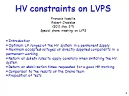
François Vazeille Robert Chadelas 2011 May 3 rd Special phone meeting on LVPS Introduction Optimum LV ranges of the HV system in a permanent supply Maximum accepted voltages of directly supplied components in a permanent working ID: 358107

components working values table working components table values time times stabilization permanent theoretical results applied limit overshoots voltages switching tests system ranges

Share:

Link:

Embed:

Download Presentation from below link

Download Presentation The PPT/PDF document "HV constraints on LVPS" is the property of its rightful owner. Permission is granted to download and print the materials on this web site for personal, non-commercial use only, and to display it on your personal computer provided you do not modify the materials and that you retain all copyright notices contained in the materials. By downloading content from our website, you accept the terms of this agreement.


Presentation Transcript

Slide1

HV constraints on LVPS

François VazeilleRobert Chadelas(2011 May 3rd)Special phone meeting on LVPS

 Introduction Optimum LV ranges of the HV system in a permanent supply Maximum accepted voltages of directly supplied components in a permanent working Return on safety rules to apply carefully when switching the HV system Return on stabilization times requested for a good HV working Comparison to the results of the Drake team Proposition of tests

1Slide2

 The sensitivity of the HV working with respect to the requested Low Voltages

has been reported in a Tilecal commissioning meeting in 2008 ( May 8th), but it does comply with a permanent working, and not for a transitory status.

https://indico.cern.ch/getFile.py/access?subContId=8&contribId=0&resId=1&materialId=slides&confId=32923 These results took also into account some safety margins of electronical components. We will remind very shortly these results that guarantee a good HV working. Then we will give the upper voltages that the supplied components can accept without damages. We will remind the safety rules to apply

when switching off/on the HV system,

and too the interest of waiting for stabilization times. Then we will explain why the comparison with the Drake team results is not yet straightforward. Finally, we will propose to agree on a strategy for the next tests at CERN.

Introduction

2Slide3

Optimum LV ranges for the HV system in a permanent supply

Requested Low Voltagesin voltsOptimum range

(Absolute values in volts) 15 V[12.0, 17.0]+ 5 V[4.5, 5.5]This concern is only with respect to the applied LVs.Other concerns should be considered about the working stability like the stabilization time, the humidity, the temperature…but it is not this concern.

Table 1: Optimum ranges of LVs

The requested nominal values are given in the first column of the Table 1.The study (reminded before) enabled to define the optimum ranges of each value for a

working in a permanent regime: they are given in the second column.

3Slide4

Maximum accepted voltages of directly supplied components

in a permanent workingReferencesTypeMax voltage (V)

MC68336CPU6.582C2509AM29F040Flash7AT25160

Eeprom

7HM62128Ram7Max 233

I/O6HCTxxx

Logic

7

ADS7820

ADC

7

Table 2: For a theoretical

supply at 5 volts

References

Type

Max voltage (V)

INA128Ampli18Max 536DAC17MPC506Mux22OPA177Ampli22OPA277Ampli36

Table 3: For a theoretical supply at  15 volts

4Slide5

Return on safety rules to apply carefully

when switching the HV systemHV Switching Procedure

OFFSwitch OFF first the HVs, then the LVs.ONSwitch ON first the LVs, then the HVs.Table 4: Safety rules in the switching of the HV system

Return on stabilization times requested for a good HV working

Two stabilization times play an important role: The stabilization time of the HV electronics itself. The stabilization time of the corresponding PMTs.Depending from the components and PMTs, these durations are variableand can go up to 10 hours and even more.

5Slide6

Comparison to the results of the Drake team

 Drake team results with respect to the HV part

Theoretical LV (V)Overshoot (V)(Nominal)Drop (V)(Nominal)+ 1516.27(14.50)14.20(14.50)- 15

16.75

(14.36)13.90(14.50)+ 56.77(5.06)4.83

(5.00)COMMENT and QUESTIONS:

●What is called ″nominal″ in this Table is not the official nominal values

which are the

“theoretical values”

of the first

column

.

● What are the dispersions on overshoot and

drop

results ?

Were they obtained from many bricks ?

Table 5: Results about the overshoots and drops6Slide7

 Comparison of Table 5 with the specifications in a continuous regime

Specifications on the optimum ranges of Table 1 - For the  15 V: applying

14.5 and 14.36 V give overshoots close to the upper limit of 17 V. It should be increased if the theoretical values were applied. This effect should be enhanced if the applied values

were in the allowed

range [15, 17]. For the + 5 V, the overshoot exceeds the upper limit. So a good HV working

is not guaranteed. It should be enhanced if we apply the allowed values

going up to 5.5 V.

- For the  15 V

, the

drops

stay above the lower limit, but

could be below

while applying a lower voltage within the optimum

range down to 12 V. For the + 5 V

, the drop is close to the lower limit of 4.5 V: a small decrease of the applied voltage (allowed down to 4.5 V) should lead below this limit. However, if we forget the possible damages to the components (see next slide),it would be not a major problem to have a bad HV working during a short time ofsome ms.Besides, as this conclusion is based on a permanent regime, it would be not betterduring the short times of overshoot and drop.7Slide8

 Specifications on the maximum voltages of Tables 3 and 4

For the  15 V, applying 14.5 V to MAX

536 gives an overshoot close to the acceptable limit, and above if the theoretical value are applied. If the allowed

range is

used above (from 15 to 17 v), MAX 536 and INA128 can be outside the acceptable limit. So

there is a risk of damaging these 2 components. For 5 V,

the risks are increased

for

MC68336 and MAX 233 because the

overshoot is reaching 6.77 V

. It is the case of

all the other components

(but for 82C250) if the maximum theoretical value of 5.5 V is applied.

The overshoots are capable of destroying most of the supplied components,

these risks being increased by using the recommended theoretical values,and still enhanced by setting higher voltages (even though they stay within the

optimum ranges of the Table 1).8Comment: MAX 233 is only used by experts when they have to test the electronics.Thus if it is damaged, it will not prevent directly the HV working but could havean induced effect on it.Slide9

In a first conclusion, based on the studies of a HV working in a permanent regime:

The HV working could be disturbed by the overshoots and undershoots, but it is likely not a major problem because it stands during a very short time, well below the stabilization times requested by HV working.

The main risks are about the overshoots being above the maximum allowed values of most of the components, but is it really dangerous during a short time ?9WARNING: Are we sure that these kinds of overshoots and/or undershoots did never occur…

in the present LVPS ?Slide10

Proposition of tests

Only systematic tests at CERN (Building 175) should allow to conclude.So the proposition is as following:Using a multimeter

, to check the applied LV’s.To repeat a big number of times the switching OFF/ON of the LVPS and HV systems, by following carefully the recommendation rules about the orders of commands: - Many times without setting ON the HV but reading only the DCS status. - From time to time (1 over 10 times), set ON the HV and check the HV values, without waiting for the stabilization time, in order to check only that the HV system is physically working.3. The

survey of the Microcontroller MC68336 is particularly important

: in the worst case, it could be destroyed. In other cases it could give no reply: in such a case, the DCS is the best way to check it. The damages could occur also on other components.4. These tests must repeated using several bricks and several drawers

in order to take into account the dispersions of

working of drawers and LVPS’s.

5.

Clermont

people

are ready to contribute to these tests at the HV level.

10