/
Tension and Compression in Trusses Tension and Compression in Trusses

Tension and Compression in Trusses - PowerPoint Presentation

danika-pritchard
danika-pritchard . @danika-pritchard
Follow
546 views
Uploaded On 2017-06-28

Tension and Compression in Trusses - PPT Presentation

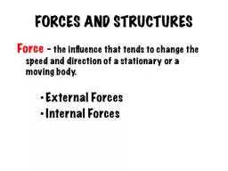
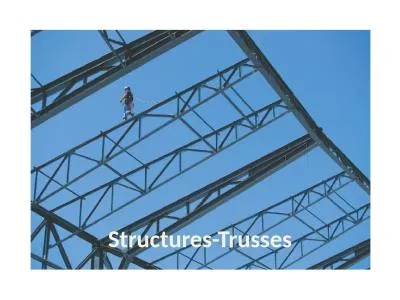
Review A truss is considered to be a solid beam full of holes A truss and beam behave similarly under the same live load The point of a truss is to disperse forces as far from the neutral axis as possible in order to resist deflection ID: 564294

compression tension truss forces tension compression forces truss joint sum members trusses force equal 100 direction vertical loaded external

Share:

Link:

Embed:

Download Presentation from below link

Download Presentation The PPT/PDF document "Tension and Compression in Trusses" is the property of its rightful owner. Permission is granted to download and print the materials on this web site for personal, non-commercial use only, and to display it on your personal computer provided you do not modify the materials and that you retain all copyright notices contained in the materials. By downloading content from our website, you accept the terms of this agreement.


Presentation Transcript

Slide1

Tension and Compression in Trusses

Review

A

truss is considered to be a solid beam full of holes. A truss and beam behave similarly under the same live load.

The point of a truss is to disperse forces as far from the neutral axis as possible in order to resist deflection.Slide2

Tension and Compression in Trusses

Review - Top-Loaded

Truss

Has a live load acting on the top of the truss (roadway on top).

The area directly beneath the load is under compression and is called the “compression zone”.

Non-vertical members next to the compression members

must be

tension members. At each joint, the sum of the vertical (and horizontal) components of the member forces must be zero.

Therefore, for a top-loaded truss, non-vertical members beyond the compression zone must be in tension and compression, alternately distributed.Slide3

Tension and Compression in Trusses

Review - Bottom-loaded

Truss

Has a live load is acting on the bottom of the truss (roadway on the bottom),

T

he area above the load is under tension and is called the “tension zone”.

Non-vertical members next to the tension members must be compression members.

Therefore, for a bottom-loaded truss, non-vertical members beyond the tension zone must also be in compression and tension, alternately distributed. Slide4

Tension and Compression in Trusses

You can mathematically analyze a truss with the “

Method of Joints

The method of joints

states:

E

ach

joint of the truss must be in

equilibrium

For

each joint, the net force in the x- and y-directions must equal zero. Slide5

Tension and Compression in Trusses

For a truss to be

effective:

the sum of the

forces

in the

x-direction must equal

zero

the

sum of the

forces

in the

y-direction must equal

zero

the

moments of force must

equal

zero

.

Y

our bridge is either top or bottom-loaded.

T

here is no horizontal component of force, therefore

Σ

F

x

=

0

Pinned and roller jointsSlide6

Tension and Compression in Trusses

To analyze a truss for static

loads

1.

Determine if

the truss is

statically determinate

.

Then you can use the static equilibrium equations to analyze the truss.

Use the equation:

2J = M + 3

where J = number of joints, and M = number of membersSlide7

Tension and Compression in Trusses

2. External Forces

Calculate the sum of the forces in the x-direction – remember to set the sum equal to zero.

Calculate the sum of the forces in the y-direction – remember to set the sum equal to zero.Slide8

Tension and Compression in Trusses

3. More External Forces

Moment

– a

moment

of force is the product of a force and its distance from an axis, which causes rotation about that axis.

Sum the moments in the y-direction to solve for the unknown. Then substitute into the external forces equation to solve for all external forces.

Start

with the sum of the moments about the first joint.

If

the joint would rotate

clockwise

when the force is applied, the moment is

negative

.

If

the joint would rotate

counterclockwise

when the force is applied, the moment is

positive

.Slide9

Tension and Compression in Trusses

4. Internal

Forces

Start with the pinned joint where you know two external forces.

Do not use moments when calculating internal forces – only external forces

.

Draw a free-body diagram at that joint.

Always

measure angles with respect to the positive x-axis

.

Solve for the forces acting on each member in the truss.

Members in compression have negative internal forces.

Members in tension have positive internal forces.

Pinned and roller jointsSlide10

Tension and Compression in Trusses – Analyzing your bridge

We will say that your bridge is vertically loaded with 100 N (about 22.4

lbs

) of force downward (-100 N). That means that the sum of the forces in the vertical direction must equal 100 N.

Σ

F

y

= 100, therefore

F

y

(joint1)

+

F

y

(final joint)

= 100

Start with the sum of the moments about the first joint.

Σ

M

(joint 1)

= (100 N x the distance the force is from the joint, in meters) + (

Fy

on the opposing joint x distance from joint) = 0