/
International Heat Pipe Conference (13 IHPC), Shanghai, China, Septemb International Heat Pipe Conference (13 IHPC), Shanghai, China, Septemb

International Heat Pipe Conference (13 IHPC), Shanghai, China, Septemb - PDF document

ellena-manuel
ellena-manuel . @ellena-manuel
Follow
455 views
Uploaded On 2015-08-28

International Heat Pipe Conference (13 IHPC), Shanghai, China, Septemb - PPT Presentation

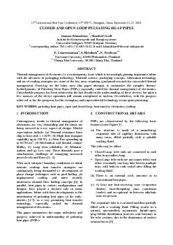
7751650160One end of the PHP tube bundle receives heattransferring it to the other by a pulsating action ofthe working fluid generating in general acapillary slug flowWhile in operat ID: 117165

+($775$16)(50(&+$1 60One end the PHP

Share:

Link:

Embed:

Download Presentation from below link

Download Pdf The PPT/PDF document "International Heat Pipe Conference (13 I..." is the property of its rightful owner. Permission is granted to download and print the materials on this web site for personal, non-commercial use only, and to display it on your personal computer provided you do not modify the materials and that you retain all copyright notices contained in the materials. By downloading content from our website, you accept the terms of this agreement.


Presentation Transcript

International Heat Pipe Conference (13 IHPC), Shanghai, China, September 21-25, 2004.&/26('$1'23(1/22338/6$7,1*+($73,3(66DPHHU.KDQGHNDU0DQIUHG*UROOInstitut für Kernenergetik und EnergiesystemeUniversität Stuttgart, 70569 Stuttgart, Germany corresponding author: Tel: (+49) 711 685-2142, E-mail: khandekar@ike.uni-stuttgart.de3&KDURHQVDZDQ65LWWLGHFK37HUGWRRQ Naresuan University, 65000 Phitsanulok, Thailand Chiang Mai University, 50200 Chiang Mai, Thailand$%675$&7Thermal management of electronics is a contemporary issue which is increasingly gaining importance inlinewith the advances in packaging technology. Material science, packaging concepts, fabrication technologyand novel cooling strategies are some of the key areas requiring synchronal research for successful thermalmanagement. Focusing on the latter area, this paper attempts to summarize the complex thermo-hydrodynamics of Pulsating Heat Pipes (PHPs), especially suited for thermal management of electronics.Considerable progress has been achieved in the last decade in the understanding of these devices but quite afew nuances of the device operation still remain unexplored or unclear. Nevertheless, with the progressachieved so far, the prospects for this exemplary and unprecedented technology seems quite promising..(:25'6 pulsating heat pipes, open and closed loop, heat transfer, electronics cooling.Contemporary trends in thermal management ofelectronics are very demanding and the limits arebeing stressed in every aspect of design. Marketexpectations include: (a) Thermal resistance fromchip to heat sink 1 K/W, (b) High heat transportcapability up to 250 W), (c) Heat flux spreading upto 60 W/cm, (d) Mechanical and thermal compa-tibility, (e) Long term reliability, (f) Miniatur-ization, and (g) Low cost. These demands pose asimultaneous challenge of managing increasedpower levels and fluxes [1, 2].With such stringent boundary conditions in mind,neoteric cooling/ heat transfer strategies arecontinuously being demanded i.e. development ofphase change techniques such as pool boiling, jetimpingement cooling and more recentlymini/micro channel flow boiling concepts [3]. Inparallel, heat pipes in various configurations anddesigns, have played a decisive role in manyapplications. Inline with these developments is theintroduction of pulsating heat pipes in the early-nineties [4-7], as a very promising heat transfertechnology, especially suited for thermalmanagement of electronics.This paper summarizes the major milestones andprogress achieved in understanding of pulsatingheat pipes (PHPs).&216758&7,21$/'(7$,/6PHPs are characterized by the following basicfeatures (refer Figure 1):The structure is made of a meandering/serpentine tube of capillary dimensions withmany turns, filled partially with a suitableworking fluid.This tube may be either:Closed Loop: tube ends are connected to eachother in an endless loop.Open Loop: tube ends are not connected to eachother; essentially one long tube bent in multipleturns with both its ends sealed after filling theworking fluid.There is no internal wick structure as inconventional heat pipes.At least one heat-receiving zone (evaporator/heater), heat-dissipating zone (condenser/cooler) and an optional in-between adiabaticzone are present.The serpentine tube is evacuated and then partiallyfilled with a working fluid. Filling results in anatural, uncontrolled, asymmetric liquid-vapor,plug-bubble distribution (uneven void fraction) inthe tube sections, due to the dominance of surfacetension forces [8]. +($775$16)(50(&+$1,60One end of the PHP tube bundle receives heat,transferring it to the other by a pulsating action ofthe working fluid, generating, in general, acapillary slug flow.While in operation, there exists a temperaturegradient between the heated and cooled end. Smalltemperature differences also exist amongst theindividual 'U' bends of the evaporator andcondenser due to local non-uniform heat transferrates which are always present in real systems.Since each tube section between the evaporatorand the condenser has a different volumetricdistribution of the working fluid, the pressure dropassociated with each sub-section is different. Thiscauses pressure imbalances leading to thermallydriven two-phase flow instabilities eventuallyresponsible for the thermofluidic transport. Bubblegeneration processes in the heater tubes sectionsand condensation processes at the other end createa sustained ‘non-equilibrium’ state as the internalpressure tries to equalize within the closed system.Thus, a self-sustained thermally driven oscillatingflow is obtained. There occurs no 'classical steadystate' in PHP operation as far as the internalhydrodynamics is concerned. Instead, pressurewaves and fluid pulsations are generated in each ofthe individual tube sections, which interact witheach other generating secondary/ ternaryreflections with perturbations [8, 9]. It will beappreciated that PHPs are complex heat transfersystems with a very strong thermo-hydrodynamiccoupling governing the thermal performance. Thecooling philosophy draws inspiration fromconventional heat pipes on one hand and single-phase forced flow liquid cooling on the other.Thus, the net heat transfer is a combination of thesensible heat of the liquid plugs and the latent heatof the vapor bubbles. The construction of PHPs issuch that on a macro level, heat transfer can becompared to an extended surface ‘fin’ system.Simultaneously, the internal fluid flow may becompared to flow boiling in narrow channels.PHPs may never be as good as an equivalent heatpipe or thermosyphon system which are based onpure latent heat transfer. If the behavior is wellunderstood, the performance may be optimizedtowards classical heat pipes/thermosyphons, as alimiting case. At the least, the manufacturingcomplexities of heat pipes will be avoided. Ascompared to an equivalent metallic finned array, atthe least there will be a weight advantage. Finally,there is always a reliability advantage because ofthe absence of an external mechanical pump [10].The available experimental results and trendsindicate that any attempt to analyze PHPs mustaddress two strongly interdependent vital aspectssimultaneously, viz. system ‘thermo’ and ‘hydro-dynamics’. Figure 2 shows the genealogy of two-phase passive devices. Although the representationis not exhaustive, all the systems with relevance tothe present interest are depicted. Although all thesystems shown in Figure 2 have ‘similar’ workingprinciples, there are decisive differences thatsignificantly alter the course of mathematicalanalyses. The family can be subdivided into threemajor sub-groups, as shown. Figure 1: Schematic of open and closed loop pulsating heat pipe with a prototype :RUNLQJIOXLGILOOLQJUDWLRExperimental results so far indicate that there is anoptimum filling ratio for proper PHP operation (inthe pulsating mode of operation). This optimum,however, is not sharply defined but generally is aplateau around 40% fill charge. For tube sectionswhich have sharp angled corners, it is possible thatthe optimum filling ratio with respect to the overallthermal resistance is of the order of 5% to 15%(this FR is comparable to that of conventional heatpipes). This happens because the sharp angledcorners act as a capillary pumps and the PHP startsbehaving as wickless ‘micro’ heat pipe. In such acondition, the structure can no more be called as apulsating heat pipe and although the thermalresistance is the lowest for such an operation, themaximum heat throughput is extremely limited.A too high filling ratio above the optimum leads toa decrease in the overall degree of freedom as thereare not enough bubbles for liquid pumping. Allother parameters remaining fixed, an optimumeffect of bubble pumping coupled with heattransfer from the resulting flow conditions isobtained for a certain range of the filling ratio.At 100% filling ratio, the device acts as a singlephase buoyancy driven thermosyphon [18]. In thismode too, substantial heat transfer can take place,but the action is limited to bottom heat mode only.7RWDOQXPEHURIWXUQVThe number of turns increases the level ofperturbations inside the device. If the number ofturns is less than a critical value, then there is apossibility of a stop-over phenomenon to occur. Insuch a condition, all the evaporator U-sectionshave a vapor bubble and the rest of the PHP hasliquid. This condition essentially leads to a dry outand small perturbations cannot amplify to make thesystem operate self-sustained.If the total heat throughput is defined, increasingthe number of turns leads to a decrease in heat fluxhandled per turn. Thus, an optimum number ofturns exits for a given heat throughput.2SHUDWLQJRULHQWDWLRQApart from simplicity of design, one of thestrongest cases in favor of pulsating heat pipes isthat their thermal performance is independent ofthe operating orientation. Nevertheless there aresome contradicting trends in the literature. In somestudies either there was a large variation ofperformance with device orientation, or horizontalas well as anti-gravity (heater-up) operation wasnot achieved at all [15, 17, 22]. Several resultsfrom other sources for a multi-turn CLPHP suggestthat horizontal operation is possible albeit not asgood as the vertical operation [14, 23, 24]. Somestudies indicate near complete performanceindependence with orientation [6, 7, 25]. Theseapparently contradictory and uncomplimentaryresults seem to suggest that requirements for anorientation independent operation are:sufficiently large number of PHP turns, whichis responsible for a higher degree of internalperturbations and inhomogeneity of thesystem,a high input heat flux leading to higher‘pumping power’ and enhanced instabilities,these two aspects are not mutually exclusiveand must simultaneously be satisfied.The results of Akachi [6, 7], Charoensawan et al.[26] and Khandekar et al. [27] tend to support thefirst hypothesis. They conclude that a certaincritical number of turns is required to makehorizontal operation possible and also to bridge theperformance gap between vertical and horizontaloperation. This is attributed to increase in theoverall level of internal perturbations. The secondhypothesis is tentatively supported by the fact thateven for vertical operation, there is a criticalminimum input heat flux requirement to initiateself-excited oscillations [9-11, 16, 17, 20, 28]. Inthe absence of gravity, this minimum heat flux islikely to be higher.6HQVLEOHYVODWHQWKHDWThe net heat transfer is a combination of thesensible heat of the liquid plugs and the latent heatof the vapor bubbles. If the internal flow patternremains predominantly in the slug flow regime (asin case of OLPHPs and in case of CLPHPs at lowheat fluxes), then it has been demonstrated thatlatent heat will not play a dominant role in theoverall heat transfer [9, 28]. If there is a transitionto annular flow under the imposed thermo-mechanical boundary conditions (in case ofCLPHPs), then the dominance of latent heatincreases leading to better performance. The mostinteresting (disturbing!) aspect is the fact that thebest performing CLPHP no longer behaves as apulsating device. Alternating tubes then have slugflow and annular flow and the bulk flow takes afixed direction. Strictly speaking, the termpulsating ‘heat pipes’ then becomes a misnomer. 6800$52)5(68/76)25&/26('/2233+3VThe experimental results presented in this sectionsummarize the general phenomenological trendsfor CLPHPs.Figure 4 shows the details of a CLPHP made ofcopper tube. The set-up consisted of a copperblock of size 130 x 25 x 25 mm forming theevaporator. This cooper block was fitted with fourcircular cartridge AC heaters (ø 10.0 x 25 mm).Five thermocouples, suitably placed as shown,measured the average evaporator copper blocktemperature. The U-turns of the CLPHP weresoldered into the evaporator block. The safemaximum heat flux (limited by set-up safety)based on the U-turn tube section area soldered inthe evaporator block was about 12 W/cmThe CLPHP was formed from copper tube (ID 2.0mm, OD 3.0 mm), with 20 turns on each side (atotal of 40 tube sections), having a staggered pitchof 10 mm between the respective tube sections.The total length of the tube used was 5.4 m with afilling volume of 17.0 cc. Leaving apart the weldedlength of the U-turns embedded into the evaporatorblock, the entire CLPHP was cooled by forced aircooling. The average air velocity was 3.5 m/s withambient air temperature of 27°C ±1.5°C.The results are shown in Figures 5-8. While theresults are self explanatory, the following are themain conclusions:A combination of large number of turns andhigh input heat flux ensures continuousCLPHP operation in any orientation withoutappreciable change in thermal performance.Both the requirements should be simulta-neously satisfied to achieve this goal. Ingeneral, start-up by a step power level is onlypossible beyond a minimum heat flux. Thisminimum start-up power was much smaller invertical the bottom heat mode than in thevertical anti-gravity mode. Beyond the criticalheat flux, no ‘stop-over’ was ever detected andcontinuous operation was always achieved.In general, start-up by a step power level isonly possible beyond a minimum heat flux.This minimum start-up power was muchsmaller in vertical the bottom heat mode thanin the vertical anti-gravity mode. Beyond thecritical heat flux, no ‘stop-over’ was everdetected and continuous operation was alwaysachieved.The thermal resistance continuously decreaseswith increasing heat input until heat transfergets limited by the external air-side heattransfer coefficient.Although an optimum filling ratio exists, thesensitivity of the filling ratio parameter is notvery high within the limits of 30% to 70%.This sensitivity further reduces with increasingheat input. At high enough heat input (with FRbetween 30% to 70%), the performance isnearly independent of the global orientation. Figure 4: Schematic details of the experimental set-up 6800$52)5(68/76)2523(1/2233+36In contrast to CLPHPs, there is no possibility of anoverall flow circulation to develop in OLPHPs.Thus, the possibility of the development of wellstructured circulating annular flow is also non-existent. The flow remains in the oscillatingcapillary slug flow regime with long vapor bubblesforming at higher heat fluxes. In addition, thepossibility of counter-current flow is also enhancedin case of OLPHPs. Since local internal heattransfer usually enhances in the convective annularflow regime, CLPHPs in general show betterperformance than OLPHPs. Of course, if theoverall heat transfer is limited by the externalambient heat transfer characteristics (as is usuallythe case in air cooling), then the performance ofthe two types may be nearly comparable.Experimental results on OLPHPs have beenreported in the original patent by Akachi [4-6] fora power range of 5 to 90 W in top and bottomheating mode with an average thermal resistanceranging from 0.64 to 1.16 K/W (R-142b).Maezawa et al. [23] studied an OLPHP consistingof 20 turns of copper tube (ID 1.0 mm) of totallength 24 m. R-142b was used as the workingfluid. Fill charge and inclination were varied andthe temperature fluctuations at the adiabatic wallsection were also recorded.Kawara et al. [29] have undertaken a visualizationstudy of an OLPHP employing proton radiographyvisualization. A 20.0 mm proton beam was passedthrough the test section and converted to visiblelight by a fluorescent screen. The PHP was formedof rectangular grooves of size 0.6 x 0.7 mm in a190 x 50 x 1.3 mm base plate. The set-up detailsalong with the radiographs are shown in Figure 9.TS-Heatronics Co. Ltd., Japan have developed arange of PHPs including design variations termedas ‘Heat Lane’ and ‘Kenzan’ fins [30]. Materialcombinations, e.g. SS-liquid N, Al-R142 andcopper with water, methanol, R113 and R142bhave been tested. Thermal resistance of K/W at a cooling air velocity of 3 m/s wasobtained for Kenzan fins (outside dim. 60.0 x 60.0x 65.0 mm) fabricated from copper tubes (ID/OD0.7/1.0 mm) filled with R142b, having 152 turnsand soldered to a copper heat input pad. SimilarKenzan fins, have been used for cooling MCMsand IGBTs.Figure 10: Results by Maezawa et al. [24] Figure 9: Setup details and results by Kawara etal. [29] Maezawa et al. [24] have tested another set ofOLPHPs with R142b and water as the workingfluid with a filling ratio of 50%. The heat pipes,both having 40 turns with a total length of 52.5 mwere made of copper tube of ID 2.0 mm and 1.0mm, respectively. The effects of diameter and theworking fluid are shown in Figure 10. It can beseen that the performance for the bottom heatmode was better than for horizontal mode. Poorperformance for the top heat mode was observed.More recently Rittidech et al. [31, 32] investigatedthe effect of inclination angles and working fluidproperties for an OLPHP made of copper tubes (ID2.03 mm, L = 50 mm, 100 mm and 150mm, L = 10 m). R123, ethanol and water wereused as working fluids with a filling ratio of 50%.The evaporator and condenser sections weremaintained at fixed temperatures of 80°C (hotwater) and 20°C (water + ethylene glycol 50:50vol.), respectively. Simultaneously, a visualizationstudy on a similar glass tube set-up was alsoundertaken. Figure 11 shows the effect ofoperating inclination angle on Qmax (Qheatthroughput for the horizontal operation). Themaximum values of Qmaxfor R123, ethanol andwater are 2.19, 2.15 and 1.98 respectively. Inaddition, it was found that a working fluid withlower latent heat of vaporization exhibited a highermax. It was found that, as the evaporatorsection length decreases from 150 to 50 mm themain flow changes from slug flow together withlong slugs/ partial annular flow to slug flow withbubbly flow.'U\RXWRI2/3+3VAt a certain high heat input to the OLPHP, theperformance limit may be reached which results ina dry-out or burn-out in the evaporator. Theassociated heat flux is called the critical heat flux.The thermo-hydrodynamic model of dry-out is notyet clear. At ‘normal’ operating condition theOLPHP operates by the simultaneous oscillation ofbubble slugs and liquid plugs inside the capillarytube. If the heat flux at the evaporator section isincreased to a very high level, violent boiling willoccur with a very high evaporation rate. Theoscillation is also violent. At a specific condition,the size of bubbles in the respective evaporatortubes increases leading to partial dry-outs in sometubes. The liquid gets prevented from entering theevaporator. The accumulated heat in the evaporatorsection results in a very high wall temperatureleading to a burnout. The series of events isdepicted in Figure 12 [33].Figure 13 shows the critical heat flux at dry-out asreported by Katpradit et al. [34]. The OLPHPswere set to operate at both vertical and horizontalorientations with the working temperaturemaintained at 60 5°C. For each OLPHP, and the FR = 50%. Two copper barswere welded onto each OLPHP to form theevaporator section while the condenser sectionused a cooling water jacket. The wall temperaturesin each tube of the evaporator section werecompared for each heating step. The procedure wasrepeated until one or more wall temperatures in theevaporator section started to increase rapidlyindicating that the dry-out state had been reached.The results show that the critical heat fluxdecreased as the section length increased, andincreased with increase in the latent heat ofvaporization. It was suggested that that thedominating dimensionless parameters for heattransfer at horizontal heat mode were Ku, Land Bo while Ku, L, Ja, Bo and dominated the vertical heat mode. was chosen as an additionaldimensionless parameter to represent floodingphenomena in the vertical mode. Figure 11: Effect of inclination angle onmax for the OLPHP tested by Rittidech etal. [31]. Figure 12: Operational states of OLPHP [33] Bo: Bond number: specific heat (J/kgK)D: tube diameter (m)Eö: Eötvös numberFR: Filling Ratio (volume of liquid/inner volume of PHP at room temperature)f: friction factorg: acceleration due to gravity (m/s²): latent heat (J/kg)Ja: Jakob number = c-esatplv)T Ka: Karman number = f·(Re)Ku: Kutateladze number .02vapvapliqvaplv ) (g k: thermal conductivity (W/m·K)N: number of turnsPr: Prandtl number = k Q: heat power (W): heat flux (W/m²)Re: Reynolds numberT: temperature (K)*UHHN6\PEROV : inclination angle to the horizontal (rad) : density (kg/m : surface tension (N/m) : dynamic viscosity (N·s/m6XEVFULSWVa: adiabatic sectionc: condenser sectioncrit: criticale: evaporator sectionliq, vap: liquid, vapormax: maximummin: minimumAzar K., The History of Power Dissipation,Electronics Cooling, Vol. 6, No. 1, 2000.Available at http://electronics-cooling.com/html/articles.html.Bar-Cohen, Trends in Packaging of ComputerSystems, in Cooling of Electronic Systems,edited by Kakac S., Yüncü H. and Hijikata K.,Kulwar Acad. Pub., pp. 17-45, 1994.Lin S., Sefiane K. and Christy J., Prospects ofConfined Flow Boiling in Thermal Manage-ment of Microsystems, Applied Thermal Engg.Vol. 22, pp. 825-837, 2002.Akachi H., U. S. patent # 4921041, 1990.Akachi H., U. S. patent # 5219020, 1993.Akachi H., U. S. patent # 5490558, 1996.Akachi H., Polášek F. and Štulc P., PulsatingHeat Pipes, Proc. 5th Int. Heat Pipe Symp., pp.208-217, Melbourne, Australia, 1996.Khandekar S., Schneider M. and Groll M.,Mathematical Modeling of Pulsating HeatPipes: State of the Art and Future Challenges,Proc. 5th ASME/ISHMT Int. Heat and MassTransfer Conf., ISBN-0-07-047443-5, pp. 856-862, Kolkata, India, 2002.Groll M. and Khandekar S., Pulsating HeatPipes: A Challenge and Still UnsolvedProblem in Heat Pipe Science, Archives ofThermodynamics, ISSN 1231-0956, Vol. 23/4,pp. 17-28, 2002.Khandekar S. and Groll M., On the Definitionof Pulsating Heat Pipes: An Overview, Proc.5th Minsk Int. Conf. (Heat Pipes, Heat Pumpsand Refrigerators), Minsk, Belarus, 2003.Khandekar S. and Groll M., An Insight intoThermo-Hydraulic Coupling in Pulsating HeatPipes, Int. J. of Thermal Sciences, ISSN 1290-0729, Vol. 43/1, pp. 13-20, 2004.Khandekar S., Manyam S., Groll M. andPandey M., Two-phase Flow Modeling inClosed Loop Pulsating Heat Pipes, Proc. 13thInt. Heat Pipe Conf., Shanghai, China, 2004.Khandekar S., Thermo-hydrodynamics ofClosed Loop Pulsating Heat Pipes, DoctoralDissertation, Universität Stuttgart, Germany, Katpradit, T., Wongratanaphisan, T., Terdtoon,P., Akbarzadeh A., and Kamonpet P.,Correlation to Predict Heat TransferCharacteristics of A Closed End OscillatingHeat Pipe at Critical State, Applied ThermalEngineering, Elsevier Science, ISSN 1359-4311, (article in press), 2004.Panyoyai, N., Effects of Meandering Turns andAspect Ratios on Internal Flow Patterns ofClosed End Oscillating Heat Pipes at CriticalState, Master Thesis, Chiang Mai University,Zuo Z. J. and North M. T., Miniature HighHeat Flux Heat Pipes for Cooling Electronics,Proc. of SEE 2000, Hong Kong, pp. 573-579,Wong T., Tong B. Y., Lim S. M. and Ooi K.T., Theoretical Modeling of Pulsating HeatPipe, Proc. 11th Int. Heat Pipe Conf., pp. 159-163, Tokyo, Japan, 1999.Swanepoel G., Taylor A. and Dobson R.,Theoretical Modeling of Pulsating Heat Pipes,Proc. Int. Heat Pipe Symp. (CD), pp. 227-234,Chiang Mai, Thailand, , 2000.Shafii M. B., Faghri A. and Zhang Y., ThermalModeling of Unlooped and Looped PulsatingHeat Pipes, ASME J. Heat Tran., Vol. 123, pp.1159-1172, 2001.Zhang Y. and Faghri A., Heat Transfer in aPulsating Heat Pipe with Open End, Int. J.Heat Mass Transfer, Vol. 45, pp. 755-764,Maezawa S. Nakajima S., Gi K. and AkachiH., Experimental Study on Chaotic Behaviorof Thermohydraulic Oscillation in OscillatingThermosyphon, Heat Pipe Technology (Proc.5th Int. Heat Pipe Symp.), ISBN 0-08-042842-8, pp. 131-137, Melbourne, Australia, 1996.Maezawa S., Sato F. and Gi K., ChaoticDynamics of Looped Oscillating Heat Pipes(Theoretical Analysis on Single Loop), Proc.6th Int. Heat Pipe Symp., pp. 273-280, ChiangMai, Thailand, 2000.Khandekar S., Cui X. and Groll M., ThermalPerformance Modeling of Pulsating Heat Pipesby Artificial Neural Network, Proc. 12th Int.Heat Pipe Conf., pp. 215-219, Moscow,Russia, 2002.